2ARPHTS-T7True wireless stereo earbuds
TUOSI ELECTRONICS CO.,LTD.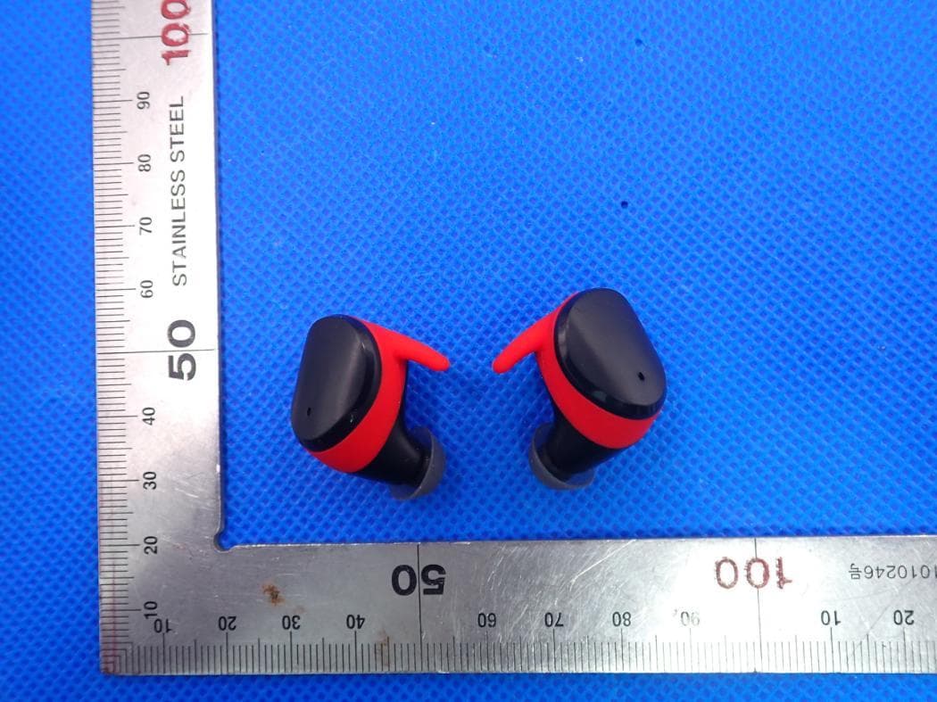
Click to zoom
Application Details
- Equipment Class
- DSS - Part 15 Spread Spectrum Transmitter
- Date of Grant
- Jul 15, 2020
- Application Purpose
- Original Equipment
- Date of Application
- Jul 15, 2020
- Equipment Note
- True wireless stereo earbuds
- Frequency Range
- 2402.00000000 - 2480.00000000
- Company
- TUOSI ELECTRONICS CO.,LTD.
- Country
- China
Documents & Files
Document Text
Text extracted from the exhibit documents filed with the FCC. Open a document above to read the original.
Users Manual
* * 1.Do not place device in very low or high temperature environment,In extreme temperature environment, earbuds may transform, Battery capacity may decrease, earbuds lifetime may be shorten. 2.Do not use earbuds in storm, The earbuds may be broken and will increase the risk of lightening stroke. 3.Do not disassemble or refit the earbuds for any reason, it make broken or born the earbuds, Please send it to sales agency to repair. 4.Only those USB charging cable qualified by us can be used, Use unqualified USB cable or charger may broke the earbuds and may cause explosion in extreme situations..It will also makes warranty invalid. 5.Repeated charging and discharging will make the battery performance reduced after sometime, this is normal for all rechargeable batteries. 6.Pls put the items and accessories to the places which can not be touched by kids or pets to avoid any unexpected accidents. War ning Tak e both earbuds out from charging case at the same time.Double click touch area of both earbuds simultaneously,Red&blue light of both earbuds will flash. If left earbud or right earbud flashs Red&blue alternatively, The earbuds paired successfully. * Earbuds Re-p airing methods Earbuds and char ging case are with built in rechargeable battary,Can not be dis-assembled ,Pls make sure the earbuds and case are fully charged before using it for first time. Charge the case Connect the USB char ging cable to the charging socket on the charging box of the headset. Connect the charging cable plug in the standard USB5V output power supply. During the charging process, the single digit of the charging box digital tube flashes. When the charging box is fully charged, the charging box's digital tube displays "100" to indicate that it is fully charged. Unplug the charging cable from the power socket. When the charging case is low, the digital tube display “15” flashes. Charge the earbuds Put the left (L) a nd right (R) earphones into the charging case. The left (L) and right (R) earphone indicator lights in solid red to enterthe charging state (the charging indicator of the charging box is always on). When the left (L) and right (R) headsets are fully charged, the indicator light will go out and the charging box will automatically turn off the power. When the headset is low on power, the headset will beep at intervals, "please charge", and the indicator will flash red at intervals. If the headset is turned off at low power during a call, it will automatically transfer the call to the phone. Accessories: V98 earbuds * 1sets Big and small e ar caps * 2 pairs User manual * 1pcs Charging cable * 1pcs In Working status: Long press on the t ouch area for 5 seconds voice prompt "Power off". Double-click on an incoming call to answer the call, click on the call to end the call. Press and hold for 2 seconds until the beep sounds,you can reject the call. Triple-tap the touch area until Siri opens Siri. When music is playing, short press to pause/play music. Next song: Right (R) headset long press 2 seconds touch area. Volume up: right (R) headset quickly "double-click" the touch area. Previous song: Left (L) headset long press 2 seconds touch area. Volume reduction: Left (L) headset quickly"double-click" the touch area. When two he adphones are used at the same time, turn off one of the headphones, the other headphones can still be used normally. The headset supports manual power on/off, long press the touch area for about 3 seconds to turn on, long press the touch area for about 5 seconds to turn off. 1.Open the cover of the charging case (the earphone is in the charging case). 2.Open the Bluetooth function of the mobile phone and search for the name "V98", click connection "V98", after the pairing successfully, then take out the headset to use. Use single earbud 1.Tak e out one of earphones, and then close the charging case. 2.The headset lights blue first, and then triple-tap the headset touch area until the headset indicator "alternately flashes red and blue" to enter pairing mode. 3.Turn on the mobile phone's Bluetooth function to search and connect to "V98", at this time a single headset can be used. Use aft er first time Aft er the second use (the earphone is in the charging box), only need to open the charging box, which can be automatically connected to the mobile phone to use (you must ensure that the Bluetooth function of the mobile phone is turned on) Produc t parameters Bluetooth v ersion:5.0 Working distance:10M Earbuds charging time:1H Charging time o f charging box: about 1.5H Standby time:about 50H Charging input:DC5 .0V=300mA Cap ac ity of charging case :400 mAh Capac ity o f earbuds:40mAh Support:ster eo mode/mono mode Batter y type:polymer li-ion battery Functions: music/voic e prompt/phone call Charging bo x dimension:60*37*28mm Earbuds dimension:22*22 *24mm Music time: 6H Talk time: 6 H Charging bo x weight: 27.5g (without earbuds) Weight o f single earphone: 4.0g User Manual How to wear L S Choose suitable Earcaps. Adjust the earbuds until you feel comfortable. How to take out Open the cover of charging case , Take the earbuds out directly How to use Touch area Earhook Indicator lights/Microphone Earcap Charge box power display Headphone battery display Charging contacts Charging port How to pair Compatible with Bluetooth V2.1+EDR or above devices. Use two earbuds together Smart connection Button functionsCharging wayPotential problems earbud flash red Insufficient power Recharge it Recharge it Can not power onInsufficient power ProblemsReasonSolution No indicator when charging Earbuds misplaced Place it correctly Power off automatically Insufficient power Recharge it Noises heard Heavy enviroment interference or earbuds far from the mobile Change the environment Put the earbuds closer to mobile Signal breaks Heavy enviroment interference or earbuds far from the mobile Change the environment Put the earbuds closer to mobile One earbud without sound Earbuds not paired successfully with eac…
Text truncated - open the document above for the full version.
Cover Letter(s)
TUOSI ELECTRONICS CO.,LTD. Room501, 5/F, No.3 building, Mengliyuan Technical Industrial Park Yousong Rd, Longhua district, Shenzhen, China Jul. 08, 2020 Federal Communications Commission 445 12 th Street SW Washington, DC 20554 Subject: Limited Agency Agreement TUOSI ELECTRONICS CO.,LTD. FCC ID: 2ARPHTS-T7 To Whom It May Concern: We, TUOSI ELECTRONICS CO.,LTD. hereby authorized Intertek Testing Services to act as our Agent for the purpose of preparing application for FCC ID number 2ARPHTS-T7) under all applicable parts of the FCC rules and regulations. The effective date of this limited agency agreement is (2020-01-13). The Limited Agency Agreement expires until further notice, unless sooner terminated or extended by written notice to Intertek Testing Services and the Federal Communications Commission. This is to advise that we are in full compliance with the Anti-Drug Abuse Act. The applicant is not subject to a denial of federal benefits pursuant to Section 5301 of the Anti-Drug Act of 1988, 21 U.S.C. 862, and no party to the application is subject to a denial of federal benefits pursuant to that section. If you have any questions or comments, please do not hesitate to contact me. Sincerely, [Signature] TUOSI ELECTRONICS CO.,LTD. Contact person: Hua Lin
Cover Letter(s)
TUOSI ELECTRONICS CO.,LTD. Room501, 5/F, No.3 building, Mengliyuan Technical Industrial Park Yousong Rd, Longhua district, Shenzhen, China Jul. 08, 2020 Federal Communication Commission Authorization and Evaluation Division FCC ID: 2ARPHTS-T7 Re: Confidentiality Request Pursuant to Sections 0.457 and 0.459 of the Commission’s Rules, the applicant hereby requests confidential treatment of information applied this application as outlined below: 1: Block Diagram 2: Schematics 3: Operational Description The above materials contain trade secrets and proprietary information not customarily released to the public. The public disclosure of these matters might be harmful to the applicant and provide unjustified benefits to its competitors. The Applicant understands that pursuant to Rules 0.457, disclosure of this Application and all accompanying documentation will not be made before the date of the Grant for this application. Sincerely, TUOSI ELECTRONICS CO.,LTD. Contact person: Hua Lin
External Photos
External Photos WHOLE VIEW OF EUT TOP VIEW OF EUT BOTTOM VIEW OF EUT FRONT VIEW OF EUT BACK VIEW OF EUT LEFT VIEW OF EUT RIGHT VIEW OF EUT Left VIEW OF EUT(PORT) Right VIEW OF EUT(PORT) Charging Dock TOP VIEW OF EUT BOTTOM VIEW OF EUT VIEW OF EUT(port)-1 VIEW OF EUT(port)-2
ID Label/Location Info
FCC ID Label Location 30mm*50mm FCC ID: 2ARPHTS-T7
Internal Photos
Internal Photos OPEN VIEW OF EUT VIEW OF BATTERY INTERNAL VIEW OF EUT-1 INTERNAL VIEW OF EUT-2 BT Antenna Right OPEN VIEW OF EUT VIEW OF BATTERY INTERNAL VIEW OF EUT-1 INTERNAL VIEW OF EUT-2 BT Antenna
RF Exposure Info
RF EXPOSURE EVALUATION 1. PRODUCT INFORMATION Product Description True wireless stereo earbuds Model Name TS-T7 FCC ID 2ARPHTS-T7 2. EVALUATION METHOD According to 447498 D01 General RF Exposure Guidance v05 The 1-g and 10-g SAR test exclusion thresholds for 100 MHz to 6 GHz at test separation distances ≤ 50 mm are determined by: [(max. power of channel, including tune-up tolerance, mW)/(min. test separation distance, mm)] ·[√f(GHz)] ≤ 3.0 for 1-g SAR and ≤ 7.5 for 10-g extremity SAR. Where f(GHz) is the RF channel transmit frequency in GHz Power and distance are rounded to the nearest mW and mm before calculation 3. CALCULATION BR/EDR: P t =3.967dBm=2.49mW The value of the Maximum output power P t is referred to the test report of the CFR47 §15.247. The result for RF exposure evaluation SAR=(2.49mW /5mm) .[√2.402GHz)]=0.77<3.0 for 1-g SAR and ≤ 7.5 for 10-g extremity SAR. 4. CONCLUSION The SAR evaluation is not required.
Test Report
Page 1 of 74 FCC Test Report Report No.: AGC04508200601FE03 FCC ID : 2ARPHTS-T7 APPLICATION PURPOSE : Original Equipment PRODUCT DESIGNATION : True wireless stereo earbuds BRAND NAME : N/A MODEL NAME : TS-T7, V98, T90, S90, T98, S98 APPLICANT : Tuosi Electronics Co., Ltd. DATE OF ISSUE : Jul. 08, 2020 STANDARD(S) : FCC Part 15.247 REPORT VERSION : V1.0 Attestation of Global Compliance (Shenzhen) Co., Ltd CAUTION: This report shall not be reproduced except in full without the written permission of the test laboratory and shall not be quoted out of context. Report No.: AGC04508200601FE03 Page 2 of 74 REPORT REVISE RECORD Report Version Revise Time Issued Date Valid Version Notes V1.0 / Jul. 08, 2020 Valid Initial Release Report No.: AGC04508200601FE03 Page 3 of 74 TABLE OF CONTENTS 1. VERIFICATION OF CONFORMITY ............................................................................................................... 5 2. GENERAL INFORMATION ............................................................................................................................ 6 2.1. PRODUCT DESCRIPTION ..................................................................................................................... 6 2.2. TABLE OF CARRIER FREQUENCYS ..................................................................................................... 6 2.3. RECEIVER INPUT BANDWIDTH ............................................................................................................ 7 2.4. EXAMPLE OF A HOPPING SEQUENCY IN DATA MODE ....................................................................... 7 2.5. EQUALLY AVERAGE USE OF FREQUENCIES AND BEHAVIOUR ........................................................ 7 2.6. RELATED SUBMITTAL(S) / GRANT (S) .................................................................................................. 8 2.7. TEST METHODOLOGY .......................................................................................................................... 8 2.8. SPECIAL ACCESSORIES ....................................................................................................................... 8 2.9. EQUIPMENT MODIFICATIONS .............................................................................................................. 8 3. MEASUREMENT UNCERTAINTY ................................................................................................................. 9 4. DESCRIPTION OF TEST MODES ............................................................................................................... 10 5. SYSTEM TEST CONFIGURATION ............................................................................................................. 11 5.1. CONFIGURATION OF EUT SYSTEM .................................................................................................... 11 5.2 EQUIPMENT USED IN TESTED SYSTEM .............................................................................................. 11 5.3. SUMMARY OF TEST RESULTS ............................................................................................................. 11 6. TEST FACILITY ........................................................................................................................................... 12 7. PEAK OUTPUT POWER ............................................................................................................................. 13 7.1. MEASUREMENT PROCEDURE ........................................................................................................... 13 7.2. TEST SET-UP (BLOCK DIAGRAM OF CONFIGURATION) ................................................................... 13 7.3. LIMITS AND MEASUREMENT RESULT ............................................................................................... 14 8. 20DB BANDWIDTH ..................................................................................................................................... 20 8.1. MEASUREMENT PROCEDURE ........................................................................................................... 20 8.2. TEST SET-UP (BLOCK DIAGRAM OF CONFIGURATION) ................................................................... 20 8.3. LIMITS AND MEASUREMENT RESULTS ............................................................................................. 21 9. CONDUCTED SPURIOUS EMISSION ........................................................................................................ 27 9.1. MEASUREMENT PROCEDURE ........................................................................................................... 27 9.2. TEST SET-UP (BLOCK DIAGRAM OF CONFIGURATION) ................................................................... 27 9.3. MEASUREMENT EQUIPMENT USED .................................................................................................. 27 Report No.: AGC04508200601FE03 Page 4 of 74 9.4. LIMITS AND MEASUREMENT RESULT ............................................................................................... 27 10. RADIATED EMISSION ............................................................................................................................... 40 10.1. MEASUREMENT PROCEDURE ......................................................................................................... 40 10.2. TEST SETUP ....................................................................................................................................... 42 10.3. LIMITS AND MEASUREMENT RESULT ............................................................................................. 43 10.4. TEST RESULT ..................................................................................................................................... 43 11. NUMBER OF HOPPING FREQUENCY ..................................................................................................... 53 11.1. MEA…
Text truncated - open the document above for the full version.
Test Setup Photos
Test Setup Photos RADIATED EMISSION TEST SETUP BELOW 1GHZ RADIATED EMISSION TEST SETUP ABOVE 1GHZ
Contact Information
Applicant
Hua Lin
Technical Contact
Attestation of Global Compliance (Shenzhen) Co., LYimi Zhao
[email protected]86-755-29081977
2F.,No.2 Building, Huafeng No.1 Technical Industri · Shenzhen · China
Test Firm
Attestation of Global Compliance (Shenzhen) Co., LDoris Li
[email protected]+86-755-25234088
Technical Specifications
| # | Rule Parts | Frequency Range | Power Output |
|---|---|---|---|
| 1 | 15C | 2.40 GHz - 2.48 GHz | 2.49 mW |
Other Applications from TUOSI ELECTRONICS CO.,LTD.
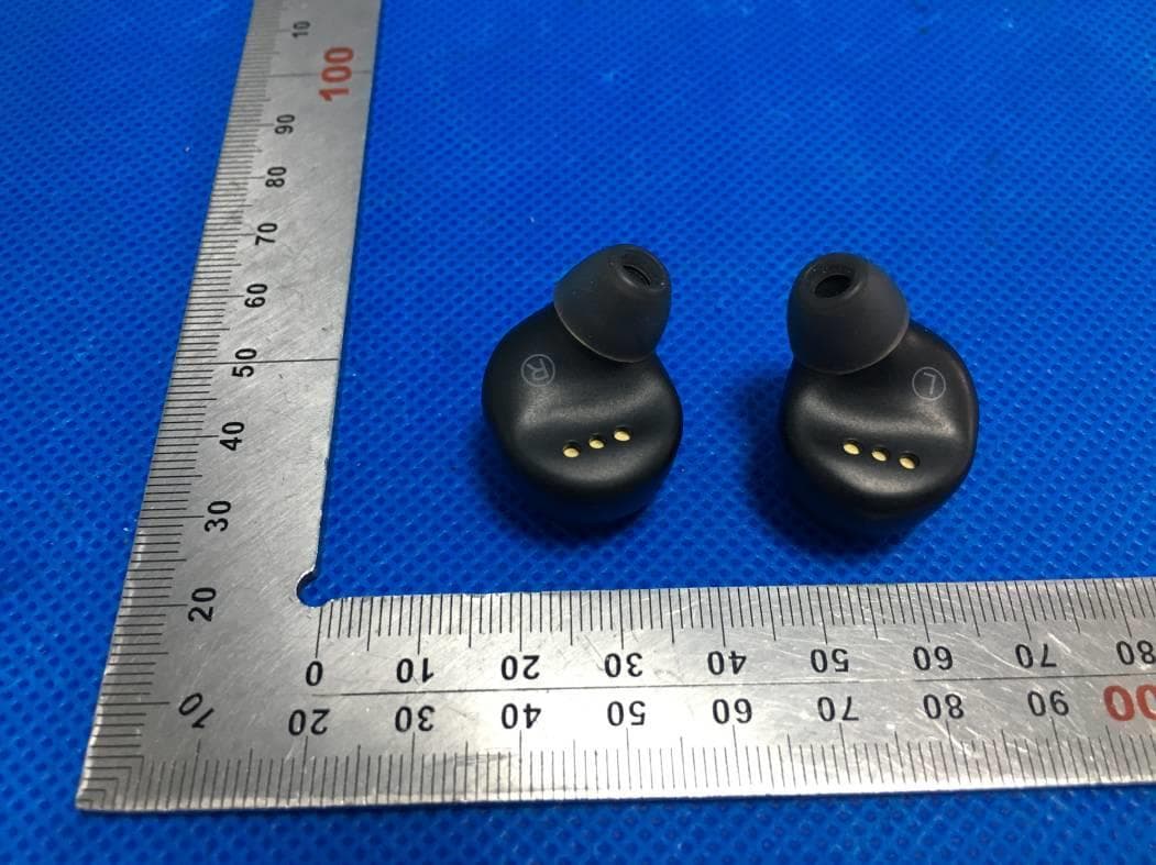
2ARPHTS-T5
Jun 02, 2020True wireless stereo earbuds
Equipment Class
DSS - Part 15 Spread Spectrum Transmitter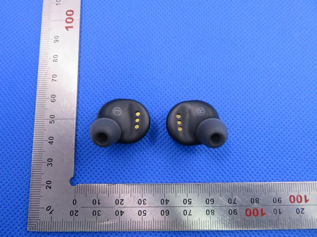
2ARPHTS-T3
Jan 14, 2020True wireless stereo earbuds
Equipment Class
DSS - Part 15 Spread Spectrum Transmitter