2ARTH-SAFESSASafe-T-Switch SSA
RectorSeal, LLC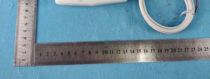
Click to zoom
Application Details
- Equipment Class
- DTS - Digital Transmission System
- Date of Grant
- Jun 07, 2022
- Application Purpose
- Original Equipment
- Date of Application
- Jun 07, 2022
- Equipment Note
- Safe-T-Switch SSA
- Frequency Range
- 2412.00000000 - 2462.00000000
- Company
- RectorSeal, LLC
- Country
- United States
Documents & Files
Document Text
Text extracted from the exhibit documents filed with the FCC. Open a document above to read the original.
Users Manual
INTRODUCTION Safe‐T‐Switch SSA is a SMART home device that allows your HVAC Condensate Switch to alert the homeowner of any service interruptions due to excessive condensate accumulating within the drain pan. FEATURES ‐ Battery operated – 3 (AA) batteries (not included), no hard‐wire install needed ‐ No App needed – simple set‐up allows for Text Messages and/or emails to be sent to 1‐2 people PRODUCT REQUIREMENTS ‐ iPhone/iPad – iOS version 9.0 or later ‐ Android – 4.4.x or later ‐ Mac – OS 10.11 or later ‐ Windows – Windows 7 or later ‐ A Smartphone/Tablet capable of connecting to the internet via Wi‐Fi, where the device will be installed ‐ Access to a Wi‐Fi network and password where the SSA will be installed 1) WIRING THE DEVICE ‐ Be sure to power off the HVAC system at the thermostat, on the system the Safe‐T‐Switch SSA is being installed (if multiple HVAC systems are present) ‐ Locate your condensate Switch(es) to your drain pan(s) NOTE – For multiple overflow switches on one system, wire them in‐series and follow steps below ‐ 2 wire NC float switch instructions BEFORE YOU BEGIN... Read these instructions in their entirety before configuring your Safe‐T‐Switch SSA. Check RectorSeal.com for the latest product information, instructions, and videos. o Connect the 2 wires from the condensate switch to the 2 input wires of the Safe‐T‐ Switch SSA o Break the Red Thermostat wire and connect one end to the SSA output common wire and connect the other end to SSA output NC wire. Use wire nuts for your connections o INSTALL OPTION – Break Yellow to keep fan running during an event NOTE ‐ Unit will not run until SSA registration is complete – See Step 2 ‐ 5 wire condensate switch instructions o Connect the Common and NC wires from the condensate switch to the 2 input wires of the Safe‐T‐Switch SSA o Break the Red Thermostat wire and connect one end to the SSA output common wire and connect the other end to SSA output NC wire. Use wire nuts for your connections o INSTALL OPTION – Break Yellow to keep fan running during an event NOTE ‐ Unit will not run until SSA registration is complete – See Step 2 NOTE ‐ Use NO wire of the SSA for systems that require NO functions such as an external alarm INSTALL BATTERIES ‐ To access the battery compartment, locate the bottom screw, remove the screw, and remove the cover plate ‐ Install the batteries according to the battery images, paying attention to which end is (+) and (‐) ‐ Wait to re‐install the battery cover until after the registration and device set‐up is complete. The device registration and set‐up is time sensitive, and we advise moving forward to registering the device immediately after the 3 rd battery is installed. 2) CONNECTING TO Wi‐Fi & REGISTERING THE DEVICE ‐ After installing the 3 rd (AA) battery, go to the Wi‐Fi Search function of your Smartphone ‐ Look for the “RectorSeal XX.XX.XX” and select to connect ‐ A warning may pop up asking to remain connected to the internet – select “YES” o If the automated pop‐up to the registration portal fails to launch (due to security settings on the phone) please manually open a web browser (Internet Explorer, Firefox, Chrome, Safari, etc...) on the phone and type in the following IP address: 192.168.4.1 ‐ The web browser will prompt the registration portal o Go to “Select Wi‐Fi Network” and select the homeowner’s Network o Enter the Password for this network o Fill in the following contact information for Homeowner #1 Name Email Mobile phone with Text messaging capability (NOTE – at least 1 (Email or Mobile) must be entered for the homeowner to be alerted, recommendation is to add both. Skipping this step will result in no alerts being sent to the homeowner) Home Address o Fill in the contact information for Homeowner #2 or other person (OPTIONAL) Examples could be Property Manager, Maintenance Manager, HVAC Contractor, etc... Repeat entering the user data above ‐ After successfully entering the information, a confirmation email and/or text will be sent ‐ Replace the battery cover and replace the screw. ‐ Use the included mounting fabric to position the device out of the way, or use a screw to attach the device on a stud/wall (No mounting screw included) 3) TESTING ‐ Restore power to the HVAC System and turn the AC on at the thermostat ‐ While the system is running, go back to the condensate switch and simulate an event ‐ Testing on a mechanical float switch o Simply lift the float and wait for the unit to turn off o After a minute the AC System will shut off, and a text and/or an email alert will be sent within a minute (varying internet speeds may take longer) o After you’ve received the notifications, release the float and the unit will restore power (there may be a time delay due to the system/thermostat) ‐ Testing on an electric switch o Use water or metal across the probes and wait for the unit to turn off o After a minute the AC System will shut off, and a text and/or an email alert will be sent within a minute (varying internet speeds may take longer) o After you’ve received the notifications, remove the connection to the probes, and the unit will restore power (there may be a time delay due to the system/thermostat) FREQUENTLY ASKED QUESTIONS – FAQ Q: I changed my router/Modem, how do I change my settings? A: Push the reset button twice, or remove and replace the batteries, and repeat step 2 Q: I moved into a house with one of these installed, how do I reset the settings? A. Push the reset button twice, or remove and replace the batteries, and repeat step 2 Q: Can I use Lithium or rechargeable batteries in the SSA device? A: We recommend using Alkaline batteries with this device to get the longest life out of the battery. FCC Statement This equipment has been tested and found to comply with the limits for a Class B digital device, pursuant to part 15 of the FCC Rules. These limits are designed to provide reasonable protection against harmful interference in a residential installat…
Text truncated - open the document above for the full version.
External Photos
Page 1 of 4 FCC ID: 2ARTH-SAFESSA Dongguan Yaxu (AiT) Technology Limited No.22, Jinqianling 3rd Street, Jitigang, Huangjiang, Dongguan, Guangdong, China. External Photos Photo 1 Photo 2 Page 2 of 4 FCC ID: 2ARTH-SAFESSA Dongguan Yaxu (AiT) Technology Limited No.22, Jinqianling 3rd Street, Jitigang, Huangjiang, Dongguan, Guangdong, China. Photo 3 Photo 4 Page 3 of 4 FCC ID: 2ARTH-SAFESSA Dongguan Yaxu (AiT) Technology Limited No.22, Jinqianling 3rd Street, Jitigang, Huangjiang, Dongguan, Guangdong, China. Photo 5 Photo 6 Page 4 of 4 FCC ID: 2ARTH-SAFESSA Dongguan Yaxu (AiT) Technology Limited No.22, Jinqianling 3rd Street, Jitigang, Huangjiang, Dongguan, Guangdong, China. Photo 7 ------End------
ID Label/Location Info
FCC ID Label FCC ID:2ARTH-SAFESSA
Internal Photos
Page 1 of 4 FCC ID: 2ARTH-SAFESSA Dongguan Yaxu (AiT) Technology Limited No.22, Jinqianling 3rd Street, Jitigang, Huangjiang, Dongguan, Guangdong, China. Internal Photos Photo 1 Photo 2 Page 2 of 4 FCC ID: 2ARTH-SAFESSA Dongguan Yaxu (AiT) Technology Limited No.22, Jinqianling 3rd Street, Jitigang, Huangjiang, Dongguan, Guangdong, China. Photo 3 Photo 4 Antenna Page 3 of 4 FCC ID: 2ARTH-SAFESSA Dongguan Yaxu (AiT) Technology Limited No.22, Jinqianling 3rd Street, Jitigang, Huangjiang, Dongguan, Guangdong, China. Photo 5 Photo 6 Page 4 of 4 FCC ID: 2ARTH-SAFESSA Dongguan Yaxu (AiT) Technology Limited No.22, Jinqianling 3rd Street, Jitigang, Huangjiang, Dongguan, Guangdong, China. Photo 7 ------End------
RF Exposure Info
RF Exposure evaluation FCC ID: 2ARTH-SAFESSA Exposure category: General population/uncontrolled environment EUT Type: Production Unit Device Type: Mobile Device 1. Reference According to §1.1307(b)(1), systems operating under the provisions of this section shall be operated in a manner that ensures that the public is not exposed to radio frequency energy level in excess of the Commission’s guidelines. According to §1.1310 and §2.1091 RF exposure is calculated. KDB447498 D01: Mobile and Portable Devices RF Exposure Procedures and Equipment Authorization Policies 2. Limit Limits for Maximum Permissible Exposure (MPE)/Controlled Exposure Frequency Range(MHz) Electric Field Strength(V/m) Magnetic Field Strength(A/m) Power Density (mW/cm²) Averaging Time (minute) Limits for Occupational/Controlled Exposure 0.3 – 3.0 3.0 – 30 30 – 300 300 – 1500 1500 – 100,000 614 1842/f 61.4 / / 1.63 4.89/f 0.163 / / (100) * (900/f 2 )* 1.0 f/300 5 6 6 6 6 6 Limits for Maximum Permissible Exposure (MPE)/Uncontrolled Exposure Frequency Range(MHz) Electric Field Strength(V/m) Magnetic Field Strength(A/m) Power Density (mW/cm²) Averaging Time (minute) Limits for Occupational/Controlled Exposure 0.3 – 3.0 3.0 – 30 30 – 300 300 – 1500 1500 – 100,000 614 824/f 27.5 / / 1.63 2.19/f 0.073 / / (100) * (180/f 2 )* 0.2 f/1500 1.0 30 30 30 30 30 F=frequency in MHz *=Plane-wave equivalent power density 3. MPE Calculation Method Predication of MPE limit at a given distance Equation from page 18 of OET Bulletin 65, Edition 97-01 S=PG/4πR² Where: S=power density P=power input to antenna G=power gain of the antenna in the direction of interest relative to an isotropic radiator R=distance to the center of radiation of the antenna 4. Antenna Information Only use antennas certificated as follows provided by manufacturer; Antenna No. Model No. of antenna: Type of antenna: Gain of the antenna (Max.) Frequency range: 2.4GWIFI / PCB Antenna 1dBi for 2412-2462MHz; 5. Manufacturing Tolerance WIFI(Peak) IEEE 802.11b (PEAK) Antenna 1 Frequency (MHz) 2412 2437 2462 Target (dBm) 16 16 16 Tolerance ± (dB) 1.0 1.0 1.0 IEEE 802.11g (PEAK) Antenna 1 Frequency (MHz) 2412 2437 2462 Target (dBm) 14 14 14 Tolerance ± (dB) 1.0 1.0 1.0 IEEE 802.11n HT20 (PEAK) Antenna 1 Frequency (MHz) 2412 2437 2462 Target (dBm) 14 14 14 Tolerance ± (dB) 1.0 1.0 1.0 6. Standalone MPE Result As declared by the Applicant, the EUT is a wireless device used in a fix application, at least 20 cm from any body part of the user or nearby persons; from the maximum EUT RF output power, the minimum separation distance, r =20cm, as well as the gain of the used antenna is 2.54dBi, the RF power density can be obtained. Output power Modulation Type dBm mW Antenna Gain (dBi) Antenna Gain (linear) MPE (mW/cm 2 ) MPE Limits (mW/cm 2 ) 2.4GWIFI 17 50.119 1 1.259 0.01255 1.0000 Remark: 1. Output power (Peak) including turn-up tolerance; 2. MPE evaluate distance is 20cm from user manual provide by manufacturer. 7. Conclusion The measurement results comply with the FCC Limit per 47 CFR 2.1091 for the uncontrolled RF Exposure of mobile device. ----------------THE END OF REPORT---------------
Test Report
Page 1 of 37 Report No.: AIT22040102W1 Dongguan Yaxu (AiT) Technology Limited No.22, Jinqianling 3rd Street, Jitigang, Huangjiang, Dongguan, Guangdong, China. TEST REPORT Client Information: Applicant: RectorSeal, LLC Applicant add.: 2601 Spenwick Drive Houston, TX 77055 Manufacturer: HeYuan JiaChen Technology LTD. Manufacturer add.: ZiCheng Industrial Park, HeYuan City, GuangDong, China Product Information: Product Name: Safe-T-Switch SSA Model No.: Safe-T-Switch SSA Brand Name: N/A FCC ID: 2ARTH-SAFESSA Applicable standards: FCC CFR Title 47 Part 15 Subpart C Section 15.247 Prepared By: Dongguan Yaxu (AiT) Technology Limited No.22, Jinqianling 3rd Street, Jitigang, Huangjiang,Dongguan, Guangdong, China Tel.: +86-769-8202 0499 Fax.: +86-769-8202 0495 Date of Receipt: Apr. 01, 2022 Date of Test: Apr. 01, 2022~ Apr. 08, 2022 Date of Issue: Apr. 09, 2022 Test Result: Pass This device described above has been tested by Dongguan Yaxu (AiT) Technology Limited and the test results show that the equipment under test (EUT) is in compliance with the FCC requirements. And it is applicable only to the tested sample identified in the report. Note: This report shall not be reproduced except in full, without the written approval of Dongguan Yaxu (AiT) Technology Limited, this document may be altered or revised by Dongguan Yaxu (AiT) Technology Limited, personal only, and shall be noted in the revision of the document. This test report must not be used by the client to claim product endorsement. Reviewed by: Approved by: Simba Huang Seal.chen Page 2 of 37 Report No.: AIT22040102W1 Dongguan Yaxu (AiT) Technology Limited No.22, Jinqianling 3rd Street, Jitigang, Huangjiang, Dongguan, Guangdong, China. 1 Contents Page COVER PAGE 1 CONTENTS....................................................................................................................................................................2 2 TEST SUMMARY..........................................................................................................................................................5 2.1 Statement of the Measurement Uncertainty ..............................................................................5 2.2 Measurement Uncertainty .........................................................................................................5 3 TEST FACILITY.............................................................................................................................................................6 3.1 Deviation from standard............................................................................................................6 3.2 Abnormalities from standard conditions ....................................................................................6 3.3 Test Location.............................................................................................................................6 4 GENERAL INFORMATION.........................................................................................................................................7 4.1 Test frequencies........................................................................................................................8 4.2 EUT Peripheral List ...................................................................................................................8 4.3 Test Peripheral List ...................................................................................................................8 4.4 TEST METHODOLOGY............................................................................................................9 4.5 Description of Test Modes.......................................................................................................10 5 EQUIPMENT USED DURING TEST........................................................................................................................11 6 TEST RESULTS AND MEASUREMENT DATA....................................................................................................12 6.1 Antenna requirement ..............................................................................................................12 6.1.1 Standard requirement: ....................................................................................................12 6.1.2 EUT Antenna:.................................................................................................................12 6.2 On Time and Duty Cycle .........................................................................................................13 6.2.1 Standard requirement: ....................................................................................................13 6.2.2 Measuring Instruments and Setting:...............................................................................13 6.2.3 Test Procedures..............................................................................................................13 6.2.4 Test Setup Layout...........................................................................................................13 6.2.5 EUT Operation during Test .............................................................................................13 6.2.6 Test result .......................................................................................................................13 6.3 Maximum Conducted Output Peak Power Measurement .......................................................14 6.3.1 Standard requirement: ....................................................................................................14 6.3.2 Measuring Instruments: ..................................................................................................14 6.3.3 Test Procedures:.............................................................................................................14 6.3.4 Test Setup Layout..............................................................................…
Text truncated - open the document above for the full version.
Test Report
Dongguan Yaxu(AiT) Technology Limited Report No.: AIT22040102W1 FCC ID: 2ARTH-SAFESSA Page 1 of 46 Appendix C RF Test Data for 2.4GWIFI (Conducted Measurement) Product Name: Safe-T-Switch SSA Trade Mark: N/A Test Model: Safe-T-Switch SSA Environmental Conditions Temperature: 25.1° C Relative Humidity: 51.9% ATM Pressure: 100.0 kPa Test Engineer: Simba Huang Supervised by: Seal Chen Dongguan Yaxu(AiT) Technology Limited Report No.: AIT22040102W1 FCC ID: 2ARTH-SAFESSA Page 2 of 46 Contents Page COVER PAGE 1 Duty Cycle ........................................................................................................................................................................................... 3 1.1 Test Result............................................................................................................................................................................... 3 1.2 Test Graphs ............................................................................................................................................................................. 4 2 Maximum Conducted Output Power ................................................................................................................................................... 9 2.1 Test Result............................................................................................................................................................................... 9 3 -6dB Bandwidth ................................................................................................................................................................................. 10 3.1 Test Result............................................................................................................................................................................. 10 3.2 Test Graphs ........................................................................................................................................................................... 11 4 Maximum Power Spectral Density Level ........................................................................................................................................... 16 4.1 Test Result............................................................................................................................................................................. 16 4.2 Test Graphs ........................................................................................................................................................................... 17 5 Band Edge......................................................................................................................................................................................... 22 5.1 Test Result............................................................................................................................................................................. 22 5.2 Test Graphs ........................................................................................................................................................................... 23 6 Conducted RF Spurious Emission..................................................................................................................................................... 29 6.1 Test Result............................................................................................................................................................................. 29 6.2 Test Graphs ........................................................................................................................................................................... 30 7 Restrict Band ..................................................................................................................................................................................... 39 7.1 Test Result............................................................................................................................................................................. 39 7.2 Test Graphs ........................................................................................................................................................................... 41 Dongguan Yaxu(AiT) Technology Limited Report No.: AIT22040102W1 FCC ID: 2ARTH-SAFESSA Page 3 of 46 1 Duty Cycle 1.1 Test Result Mode Frequency (MHz) Antenna Duty Cycle (%) 1/T (kHz) b 2412 Ant1 99.59 0.01 b 2437 Ant1 99.61 0.01 b 2462 Ant1 99.61 0.01 g 2412 Ant1 86.95 4.55 g 2437 Ant1 86.95 4.76 g 2462 Ant1 87.03 4.76 n20 2412 Ant1 87.56 4.35 n20 2437 Ant1 87.59 4.35 n20 2462 Ant1 87.61 4.17 Dongguan Yaxu(AiT) Technology Limited Report No.: AIT22040102W1 FCC ID: 2ARTH-SAFESSA Page 4 of 46 1.2 Test Graphs Test Graphs b 2412MHz Ant1 b 2437MHz Ant1 Dongguan Yaxu(AiT) Technology Limited Report No.: AIT22040102W1 FCC ID: 2ARTH-SAFESSA Page 5 of 46 Test Graphs b 2462MHz Ant1 g 2412MHz Ant1 Dongguan Yaxu(AiT) Technology Limited Report No.: AIT22040102W1 FCC ID: 2ARTH-SAFESSA Page 6 of 46 Test Graphs g 2437MHz Ant1 g 2462MHz Ant1 Dongguan Yaxu(AiT) Technology Limited Report No.: AIT22040102W1 FCC ID: 2ARTH-SAFESSA Page 7 of 46 Test Graphs n20 2412MHz Ant1 n20 2437MHz Ant1 Dongguan Yaxu(AiT) Technology Limited Report No.: AIT22040102W1 FCC ID: 2ARTH-SAFESSA Page 8 of 46 Test Graphs n20 2462MHz Ant1 Dongguan Yaxu(AiT) Technology Limited Report No.: AIT22040102W1 FCC ID: 2ARTH-SAFESSA Page 9 of 46 2 Maximum Conducted Output Power 2.1 Test Result Mode Frequency (MHz) AntennaConducted Power (dBm)Limit (dBm) Verdict b 2412 Ant1 16.61 30 Pass b 2437 Ant1 16.74 30 Pass b 2462 Ant1 16.6 30 Pass g 2412 Ant1 14.35 30 Pass g 2437 Ant1 14.34 30 Pass g 2462 Ant1 14.29 30 Pass n20 2412 Ant1 13.35 30 Pass n20 2437 Ant1 13.39 30 Pass n20 2462 Ant1 13.24 30 Pass Dongguan Yaxu(AiT) Technology Limited Report No.: AIT22040102W1 FCC ID: 2ARTH-SAFES…
Text truncated - open the document above for the full version.
Test Setup Photos
Page 1 of 1 FCC ID: 2ARTH-SAFESSA Dongguan Yaxu (AiT) Technology Limited No.22, Jinqianling 3rd Street, Jitigang, Huangjiang, Dongguan, Guangdong, China. Test Setup Photo Radiated Emission ------End------
Contact Information
Applicant
Kathleen M Kelch(Listing Agency Representative)
Test Firm
Dongguan Yaxu (AiT) Technology LimitedCoin Tang
[email protected]+86 0769-82020499-21
Technical Specifications
| # | Rule Parts | Frequency Range | Power Output |
|---|---|---|---|
| 1 | 15C | 2.41 GHz - 2.46 GHz | 47.20 mW |