2ARUDTS6110SWWireless Subwoofer
TCL Entertainment Solutions Limited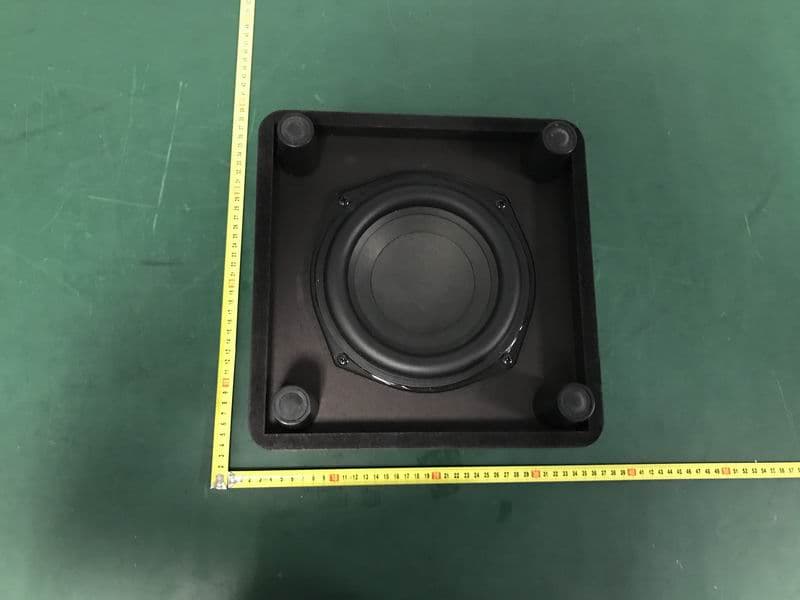
Click to zoom
Application Details
- Equipment Class
- DTS - Digital Transmission System
- Date of Grant
- Aug 04, 2020
- Application Purpose
- Original Equipment
- Date of Application
- Aug 03, 2020
- Equipment Note
- Wireless Subwoofer
- Frequency Range
- 2405.00000000 - 2477.00000000
- Country
- China
Documents & Files
Document Text
Text extracted from the exhibit documents filed with the FCC. Open a document above to read the original.
Users Manual
Quick Start Guide ALTO 6+ 2.1 Channel Sound Bar with Dolby Audio & Wireless Subwoofer 1 Safety instructions QSG AC power cord x 2 HDMI cable Optical cable Remote control AAA battery x 2 Wall mount bracket x 2Wall anchor x 2Wall mounting screw x 2 Wall mount template Quick Start Guide Safety leaflet Warranty card Warranty card What's in the box Make sure you read all the safety information before you use this product. Sound Bar main unit Subwoofer 2a Press to select the Bluetooth source. Press and hold to enter pairing mode. Press to switch the audio source among HDMI/ OPT/ AUX/USB/BT modes. Press to increase or decrease the volume level. Sound Bar main unit Volume buttons:Source button: Power button: Bluetooth button: Short press to power on/off. Long press to reset to factory default Overview AC IN 2b Overview AC IN AC IN AC input power connector > 2" TV TV 3b3b 3a 1 3 2 5 6 < 9.8' TV 20.2" Place your Sound Bar and Subwoofer The ideal place to position the Sound Bar is centered underneath your TV. For the Subwoofer working correctly, it should be less than 9.8 feet from the Sound Bar. Wall mount your Sound Bar Required tools: • Place the supplied wall mount template on the wall. Make sure the wall mount template is at least 2 inches below the center of the TV. • Use a level to make sure the wall mount template is positioned accurately. • Use the tape to stick the wall mount template firmly on the wall. • Mark on the wall using each marking on the template through the mounting holes. • Take away the wall mount template. • Drill a screw hole at each marking on the wall. 4 3b Wall mount your Sound Bar 789 Required tools: • Insert the wall anchors in the holes on the wall. • Insert the supplied screws into the hole of the wall anchors. • Fix and tighten the wall bracket screws on the wall, but leave a little space for hanging the brackets. 3b Required tools: • Screw off the rubber cushions from the soundbar.(Reserve the rubber cushions for future use) • Screw on the wall brackets to the soundbar. • Take the Sound Bar main unit close the wall and insert the head of the wall mounting screws into the holes of the brackets. • Hang the Sound Bar main unit on the wall. 10 10 11 12 13 11 12 13 Wall mount your Sound Bar AC IN Connect the Sound Bar with your TV through the supplied HDMI cable. Connect the Sound Bar and the subwoofer to the power supply with the supplied power cords. 4 4a There are 3 ways to connect in order of preference: HDMI-ARC (refer to 4a), Optical (refer to 4b)and AUX (refer to 4c) This feature requires HDMI-CEC (also commercially known as T-Link, Anynet+, SimpLink, BRAVIA Link, EasyLink or VIERA Link.) All technology names mentioned are the trademarks or registered trademarks of their respective companies. HDMI CEC Set On Connect to your TV HDMI-ARC AC IN AC IN 4b Connect the Sound Bar with your TV through the supplied Optical cable. Connect the Sound Bar and the subwoofer to the power supply with the supplied power cords. Optical Optical 4c Connect the Sound Bar with your TV through AUX cable (not supplied). Connect the Sound Bar and the subwoofer to the power supply with the supplied power cords. AC IN AUX 5a 123 4 5b Using the Remote Battery type: 1.5V AAA Alkaline battery x 2 Mute/Unmute Press and hold to activate the pairing function in Bluetooth mode or disconnect the paired device. Short press: Power off Long Press: Factory default Volume+/- Source input Press to select the equalizer (EQ) among MOVIE, MUSIC, TV. Play/pause/resume playback in Bluetooth/USB mode Next in Bluetooth/USB mode Previous in Bluetooth/USB mode Install or replace the remote batteries You can stream music from your mobile device via Bluetooth. 1. Press . 2. Press . 3. Press and hold or on the remote control or press and hold on your sound bar. > You hear a sound signal and blue light is flashing on the sound bar. > The Sound Bar is ready to pair. 4. Power on your Bluetooth device and activate its Bluetooth function. 5. Select TCL Alto 6+. > You hear a sound signal. > Pairing is successful. 6. If you want to re-pair with another device, please repeat step 3. 3 5 4 2 TCL Alto 6+ 1 6a Pair with your Bluetooth device 7 LED Indications The LED display on the Sound Bar gives you information about different status of Sound Bar. Sound Mode MOVIE MUSIC LED Indications TV Sound Bar status In standby mode In OPT mode Red Yellow In HDMI ARC modePurple In USB modeCyan In AUX modeGreen In Bluetooth modeBlue Sound Bar LED Display FAQ Does this Sound Bar work with any TV? Yes, the Sound Bar is compatible with any TV that has one of the ports below: 1. HDMI supporting ARC (preferred) 2. Optical audio output (TOSLink) 3. Headphone output When the Sound Bar and TV are both on, there is an echo effect. If you use HDMI-ARC connection, please check if the HDMI-CEC feature of your TV is turned on. This feature may be called T-Link, Anynet+, SimpLink, BRAVIA Link, EasyLink or VIERA Link . If using optical or AUX connection, simply mute the TV speaker. How many sound modes are available? Four sound modes - Movie, Music, and TV. How to clean the sound bar? Please keep your sound bar in a dry and ventilated environment. When cleaning in need, please use a soft and dry cloth to wipe it gently without water or any other cleaning agent. What are the subwoofer LED indicator status during pairing: • Standby mode: flashes slowly. • Pairing: flashes quickly. • Paired: on solidly. All technology names mentioned are the trademarks or registered trademarks of their respective companies. TS6110_NA_QSG_V0.6 support.tclusa.com support.tclcanada.com or …
Text truncated - open the document above for the full version.
Cover Letter(s)
DATE: DATE:2020.7.29 FederalCommunicationsCommission Authorization&EvaluationDivision 7345OaklandMillsRoad Columbia,Maryland21046 AuthoritytoActasAgent Onourbehalf,IappointESTTechnologyCo.,Ltd.Address:Chilingxiang,Qishantou,Santun, Houjie,Dongguan,Guangdong,China (NameofAgentcompanynameandaddress)toact asouragentinthepreparationofthisapplicationforequipmentcertification.Icertifythat submitteddocumentsproperlydescribethedeviceorsystemforwhichequipment certificationissought.Ialsocertifythateachunitmanufactured,importedormarketed,as definedintheFederalCommunicationsCommission’sregulationswillhaveaffixedtoita labelidenticaltothatsubmittedforapprovalwiththisapplication. Forinstanceswhereourauthorizedagentsignstheapplicationforcertificationonour behalf,Iacknowledgethatallresponsibilityforcomplyingwiththetermsandconditions forcertification,stillresideswithTCLEntertainmentSolutionsLimitedAddress:7/F, building22E,22scienceparkeastavenueHongKongsciencepark,SHATIN,N.T.,Hong Kong(ApplicantNameandaddress) Name:Adashi Title:engineer Company:TCLEntertainmentSolutionsLimited
Cover Letter(s)
DATE:2020.7.29 EquipmentAutorisationDivision FederalCommunicationsCommission 7435OaklandMillsRoad Columbia,MD21046 FCCID:2ARUDTS6110SW ProductName:WirelessSubwoofer RequestforConfidentiality PursuanttoSections0.457and0.459ofthecommissionsrules,weherebyrequestthat thefollowingdocumentsbeheldconfidential: (Listherethedocumentsforwhichyouareseekingconfidentiality–forexample...) Schematics Blockdiagram Operationdescription Thesematerialscontaintradesecretsandproprietaryinformationandarenot customarilyreleasedtothepublic.Thepublicdisclosureofthisinformationmightbe harmfultothecompanyandprovideunjustifiedbenefitstoourcompetitors. Name:Adashi Title:engineer Company:TCLEntertainmentSolutionsLimited
External Photos
External Photos M/N: TS6110-SW External Photos M/N: TS6110-SW External Photos M/N: TS6110-SW
ID Label/Location Info
TCL HSB347SW(TS6110) 200%图 4 0 . 0 m m Wireless Subwoofer Model: TS6110-SW Power Supply: AC 100-240V~ 50/60Hz Power Consumption: 25W Chine TCL North America 1860 Compton Ave,Corona,CA 92881,USA ATTENTION: FCC ID: 2ARUDTS6110SW IC: 24579-TS6110SW 100.0 mm CONFORMS TO UL STD.62368-1 CERTIFIED TO CSA STD.C22.2 No.62368-1 Wireless Subwoofer Model: TS6110-SW Power Supply: AC 100-240V~ 50/60Hz Power Consumption: 25W Chine TCL North America 1860 Compton Ave,Corona,CA 92881,USA ATTENTION: FCC ID: 2ARUDTS6110SW IC: 24579-TS6110SW CONFORMS TO UL STD.62368-1 CERTIFIED TO CSA STD.C22.2 No.62368-1 Wireless Subwoofer Model: TS6110-SW Power Supply: AC 100-240V~ 50/60Hz Power Consumption: 25W Chine TCL North America 1860 Compton Ave,Corona,CA 92881,USA ATTENTION: FCC ID: 2ARUDTS6110SW IC: 24579-TS6110SW CONFORMS TO UL STD.62368-1 CERTIFIED TO CSA STD.C22.2 No.62368-1
Internal Photos
Internal Photos M/N: TS6110-SW Internal Photos M/N: TS6110-SW Internal Photos M/N: TS6110-SW Internal Photos M/N: TS6110-SW
RF Exposure Info
FCC ID: 2ARUDTS6110SW EST Technology Co. ,Ltd Report No. ESTE-R2007093 Page 1 of 4 FCC 47 CFR MPE REPORT TCL Entertainment Solutions Limited Wireless Subwoofer Model Number: TS6110-SW Additional Model: TDS6110-SW, Alto 6+ SW, ***6110-SW FCC ID: 2ARUDTS6110SW Prepared for: TCL Entertainment Solutions Limited 7/F, building 22E, 22 science park east avenue, Hong Kong science park, SHATIN, N.T., Hong Kong China Prepared By: EST Technology Co., Ltd. Chilingxiang, Qishantou, Santun, Houjie, Dongguan, Guangdong, China Tel: 86-769-83081888-808 Report Number: ESTE-R2007093 Date of Test: Jun. 29~Jul. 28, 2020 Date of Report: Jul. 29, 2020 FCC ID: 2ARUDTS6110SW EST Technology Co. ,Ltd Report No. ESTE-R2007093 Page 2 of 4 Maximum Permissible Exposure 1. Applicable Standards Systems operating under the provisions of this section shall be operated in a manner that ensures that the public is not exposed to radio frequency energy level in excess limit for maximum permissible exposure. In accordance with 47 CFR FCC Part 2 Subpart J, section 2.1091 this device has been defined as a mobile device whereby a distance of 0.2m normally can be maintained between the user and the device. 1.1. Limits for Maximum Permissible Exposure (MPE) (a) Limits for Occupational/Controlled Exposure Frequency Range (MHz) Electric Field Strength (E) (V/m) Magnetic Field Strength (H) (A/m) Power Density (S) (mW/cm 2 ) Averaging Times ︱E︱ 2 ,︱H︱ 2 or S (minutes) 0.3-3.0 614 1.63 (100)* 6 3.0-30 1842/f 4.89/f (900/f)* 6 30-300 61.4 0.163 1.0 6 300-1500 F/300 6 1500-10000 5 6 (b) Limits for General Population / Uncontrolled Exposure Frequency Range (MHz) Electric Field Strength (E) (V/m) Magnetic Field Strength (H) (A/m) Power Density (S) (mW/cm 2 ) Averaging Times ︱E︱ 2 ,︱H︱ 2 or S (minutes) 0.3-1.34 614 1.63 (100)* 30 1.34-30 824/f 2.19/f (180/f)* 30 30-300 27.5 0.073 0.2 30 300-1500 F/1500 30 1500-10000 1.o 30 Note: f=frequency in MHz; *Plane-wave equivalent power density FCC ID: 2ARUDTS6110SW EST Technology Co. ,Ltd Report No. ESTE-R2007093 Page 3 of 4 1.2. MPE Calculation Method E (V/m) = d G×P×30 Power Density: Pd (W/m 2 ) = 377 E 2 E = Electric Field (V/m) P = Peak RF output Power (W) G = EUT Antenna numeric gain (numeric) d = Separation distance between radiator and human body (m) The formula can be changed to Pd = 2 d×377 G×P×30 From the peak EUT RF output power, the minimum mobile separation distance, d=0.2m, as well as the gain of the used antenna, the RF power density can be obtained FCC ID: 2ARUDTS6110SW EST Technology Co. ,Ltd Report No. ESTE-R2007093 Page 4 of 4 2. Conducted Power Result Mode Frequency (MHz) Peak output power (dBm) Peak output power (mW) Target power (dBm) Antenna gain (dBi) (Linear) 2.4G 2405 2.94 1.968 3 ±1 0 1 2439 3.13 2.056 3±1 0 1 2477 3.09 2.037 3±1 0 1 3. Calculated Result and Limit Mode Target power (dBm) Antenna gain Power Density (S) (mW /cm2) Limited of Power Density (S) (mW /cm2) Test Result (dBi) (Linear) 2.4G 2.4G 4 0 1 0.0005 1 Compiles End of Test Report
Test Report
FCC ID: 2ARUDTS6110SW EST Technology Co., Ltd Report No.ESTE-R2007092 Page 1 of 59 FCC PART 15C TEST REPORT FOR CERTIFICATION On Behalf of TCL Entertainment Solutions Limited Wireless Subwoofer Model Number: TS6110-SW Additional Model: TDS6110-SW, Alto 6+ SW, ***6110-SW FCC ID: 2ARUDTS6110SW Prepared for: TCL Entertainment Solutions Limited 7/F, building 22E, 22 science park east avenue, Hong Kong science park, SHATIN, N.T., Hong Kong China Prepared By: EST Technology Co., Ltd. Chilingxiang, Qishantou, Santun, Houjie, Dongguan, Guangdong, China Tel: 86-769-83081888-808 Report Number: ESTE-R2007092 Date of Test: Jun. 29~Jul. 28, 2020 Date of Report: Jul. 29, 2020 FCC ID: 2ARUDTS6110SW EST Technology Co., Ltd Report No.ESTE-R2007092 Page 2 of 59 TABLE OF CONTENTS Description Page TEST REPORT VERIFICATION ........................................................................................................................ 3 1. GENERAL INFORMATION ................................................................................................................. 5 1.1. Description of Device (EUT) ........................................................................................................... 5 1.2. Antenna Information ........................................................................................................................ 5 2. SUMMARY OF TEST ......................................................................................................................... 6 2.1. Summary of test result ...................................................................................................................... 6 2.2. Test Facilities .................................................................................................................................... 7 2.3. Measurement uncertainty ................................................................................................................. 8 2.4. Assistant equipment used for test ..................................................................................................... 8 2.5. Block Diagram .................................................................................................................................. 8 2.6. Test Mode ......................................................................................................................................... 9 2.7. Power Setting of Test Software ...................................................................................................... 10 2.8. Duty Cycle ...................................................................................................................................... 10 2.9. Channel List .................................................................................................................................... 12 2.10. Test Equipment List ....................................................................................................................... 13 3. 6DB BANDWIDTH ......................................................................................................................... 14 3.1. Limit ............................................................................................................................................... 14 3.2. Test Setup ....................................................................................................................................... 14 3.3. Spectrum Analyzer Setting ............................................................................................................. 14 3.4. Test Procedure ................................................................................................................................ 14 3.5. Test Result ...................................................................................................................................... 15 4. MAXIMUM PEAK OUTPUT POWER ................................................................................................ 17 4.1. Limit ............................................................................................................................................... 17 4.2. Test Setup ....................................................................................................................................... 17 4.3. Spectrum Analyzer Setting ............................................................................................................. 17 4.4. Test Procedure ................................................................................................................................ 17 4.5. Test Result ...................................................................................................................................... 18 5. POWER SPECTRAL DENSITY .......................................................................................................... 20 5.1. Limit ............................................................................................................................................... 20 5.2. Test Setup ....................................................................................................................................... 20 5.3. Spectrum Analyzer Setting ............................................................................................................. 20 5.4. Test Procedure ................................................................................................................................ 20 5.5. Test Result ...................................................................................................................................... 21 6. CONDUCTED BAND EDGE ............................................................................................................. 24 6.1. Limit ............................................................................................................................................... 2…
Text truncated - open the document above for the full version.
Test Setup Photos
Conducted Test Radiated Test (Below 1GHz) Radiated Test (Above 1GHz)
Contact Information
Applicant
Amber Wang
Test Firm
EST Technology Co., Ltd.Iceman Hu
[email protected]+86 0769-83081888
Technical Specifications
| # | Rule Parts | Frequency Range | Power Output |
|---|---|---|---|
| 1 | 15C | 2.40 GHz - 2.48 GHz | 2.06 mW |
Other Applications from TCL Entertainment Solutions Limited
2ARUDS21BW
Jun 11, 20232.1 Channel Sound Bar with Wireless Subwoofer
Equipment Class
DSS - Part 15 Spread Spectrum Transmitter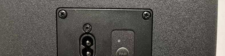
2ARUDS310WSW
Mar 23, 2023Wireless subwoofer
Equipment Class
DTS - Digital Transmission System
2ARUDS510W
Mar 22, 20235.1 Channel Sound Bar with Wireless Subwoofer and Wired Satellite Speakers
Equipment Class
NII - Unlicensed National Information Infrastructure TX
2ARUDS510WSW
Mar 22, 2023Wireless subwoofer
Equipment Class
NII - Unlicensed National Information Infrastructure TX
2ARUDS310W
Mar 22, 20233.1 Channel Sound Bar with Wireless Subwoofer
Equipment Class
DSS - Part 15 Spread Spectrum Transmitter