2ARUI-ITF20RDSmart Watch
American Exchange Time LLC
Click to zoom
Application Details
- Equipment Class
- DTS - Digital Transmission System
- Date of Grant
- Jun 02, 2020
- Application Purpose
- Original Equipment
- Date of Application
- Jun 02, 2020
- Equipment Note
- Smart Watch
- Frequency Range
- 2402.00000000 - 2480.00000000
- Company
- American Exchange Time LLC
- Country
- United States
Documents & Files
Document Text
Text extracted from the exhibit documents filed with the FCC. Open a document above to read the original.
Users Manual
WARRANTY & WATCH CARE *SEE THE QUICK START GUIDE FOR QUICK SETUP INSTRUCTIONS ROUND SMARTWATCH SAFETY & SKIN CARE We want to make sure that you’re comfortable in your new iTECH Fusion Round Smartwatch. Here are a few tips that should help: Regularly clean your smartwatch with a moist paper towel (please pat dry your watch once complete) Keep your wrist free of any dirt and oils Keep your watch loose enough so that three of your fingers can fit underneath your watch while it’s being worn (wearing a watch too tight can cause skin irritation due to sweat or other types of moisture) After a workout, it’s advised to remove your watch to allow your wrist, watch, and yourself to take a breather Adults with eczema or a skin condition should consult a physician before wearing the watch Please wear with care! WATCH CARE Clean your band regularly, especially after strenuous exercise. It is recommended to rinse your band with water or wipe it with an alcohol wipe. Do NOT use any kind of soap, hand sanitizers, or household cleaners, which could get trapped beneath the band and irritate your skin. It’s a good idea to set your watch aside for 10-15 minutes after cleaning to ensure that the device is fully free of any potential irritants and completely dry. For stains or buildup on your band, watch screen or casing, wipe the affected area with an alcohol wipe. Be sure to use a little force while wiping. If affected area is on the band, you can use warm water and a soft bristle brush to remove the dirt, stain or build up. To keep your device looking new, its recom - mended to use a microfiber cloth to wipe off any smudges or fingerprints from the casing, screen and band. Your watch should always help you feel great but if you experience any irritation or skin abrasion, please remove the watch and consult a doctor. WATCH INSTRUCTIONS FOR METAL BANDS EASY SELF-ADJUSTABLE LINKS Lift tab at end of center section on last link. Open clasp and remove link. ADJUSTING METAL BAND USING HAIR TYPE PIN CONSTRUCTION 1. Insert an awl or other slim metal tool into hole. Tool should be facing the same direction as the arrow indicated on the bottom side of the band. 2. Press tool until the pin comes through the opposite end. Using pliers, pull the pin out and remove the link. Repeat this process to remove the desired number of links. ADJUSTING WATCH BANDS FOR LEATHER, SILICONE, FABRIC & PLASTIC STRAPS Use the prong and notch system to move the prong up or down a notch to tighten or loosen and adjust to the appropriate fit for your wrist. SETTING THE TIME 1. Gently pull crown out 2. Rotate crown until hands are positioned at time. 3. Firmly push crown in. This will activate the watch. FOR STRAPS WITHOUT HOLES IN THE LUG Lay your watch with the face down (preferably on a cloth to prevent scratching your watch). You will need a sharp point or “spring bar tool” to perform the following steps. 1. Insert the sharp point between the strap and watch lug to release strap from case. 2. Once the spring bar is detached, you can remove your strap. To reattach, depress spring bar and insert into hold on the inside of the watch case lug. FOR STRAPS WITH SMALL HOLES IN THE LUG 1. Carefully place your watch face down on a folded cloth to avoid damaging the lens. 2. Carefully insert the round end of the watch tool into the hole, toward the center of the strap. The spring bar should come free of its location hole. 3. Lift out the strap and spring bar. SPRING BAR TOOLSPRING BAR TOOL FOR LEATHER, SIMULATED LEATHER, PLASTIC, FABRIC &, SILICONE BANDS CHANGING / REPLACING / ADDING / REMOVING THE BAND FROM YOUR WATCH NOTE: This equipment has been tested and found to comply with the limits for a Class B digital device, pursuant to part 15 of the FCC Rules. These limits are designed to provide reasonable protecti on against harmful interference in a residenti al installati on. This equipment generates uses and can radiate radio frequency energy and, if not installed and used in accordance with the instructi ons, may cause harmful interference to radio communicati ons. However, there is no guarantee that interference will not occur in a parti cular installati on. If this equipment does cause harmful interference to radio or television recepti on, which can be determined by turning the equipment off and on, the user is encouraged to try to correct the interference by one or more of the following measures: Reorient or relocate the receiving antenna. Increase the separati on between the equipment and receiver. Connect the equipment into an outlet on a circuit diff erent from that to which the receiver is connected. Consult the dealer or an experienced radio/TV technician for help Changes or modifi cati ons not expressly approved by the party responsible for compliance could void the user’s authority to operate the equipment. This device complies with Part 15 of the FCC Rules. Operati on is subject to the following two conditi ons: (1) this device may not cause harmful interference, and (2) this device must accept any interference received, including interference that may cause undesired operati on. FCC ID: 2ARUI-ITF20RD Limited Warranty on iTech Wearables This limited warranty gives you, the consumer, specifi c legal rights. You may also be enti tled to certain rights, which vary from state to state. The limited warranty can also be found online at htt ps://www. itechwearables.com/warranty or in the documentati on provided with the product. We warrant that during the warranty period, this product will be free from defects in materials and workmanship. We limit the durati on and remedies of all implied warranti es including, without limitati on, the warranti es of merchantability and fi tness for a parti cular purpose for the durati on of this express limited warranty. Some states do not allow limitati ons on how long an implied warranty lasts, so the above limitati on may not apply to you. Our responsibility for defecti ve goods is limited to repair,re…
Text truncated - open the document above for the full version.
Cover Letter(s)
American Exchange Time LLC Model Declaration Letter For FCC ID: 2ARUI-ITF20RD We, the undersigning company Company Name: American Exchange Time LLC Address: No.1441 Broadway 27th Floor, New York, NY 10018 Hereby confirm that the following products: Product description: Smart Watch Model Number(s): 500029, 500027, 500028 Trade name or Brand(s): iTech Fusion R All these models are the same PCB, layout and electrical circuit, the only difference is Color of the bands. City and Country: Date: Name: (this must be a person) Function: Signature: (or official company stamp) New York, USA 06/02/2020 Daisy Zhang Product Manager
Cover Letter(s)
American Exchange Time LLC Agent Authorization Company: American Exchange Time LLC Address: No.1441 Broadway 27th Floor, New York, NY 10018 Product Name: Smart Watch Model Number(s): 500029, 500027, 500028 Product Description: Smart Watch We authorize MiCOM Labs Inc., 575 Boulder Court, Pleasanton, California 94566, USA, to act on our behalf on all matters concerning the certification of above named equipment. We declare that MiCOM Labs Inc. is allowed to forward all information related to the approval and certification of equipment to the regulatory agencies as required and to discuss any issues concerning the approval application. Any and all acts carried out by MiCOM Labs on our behalf shall have the same effect as acts of our own. Signature: Date: 06/02/2020 Name: Daisy Zhang Title: Product Manager Company: American Exchange Time LLC
Cover Letter(s)
American Exchange Time LLC Office of Engineering Technology Federal Communications Commission 7435 Oakland Mills Road Columbia, MD 21046 USA Date:06/02/2020 Subject; Request for Confidentiality FCC ID: 2ARUI-ITF20RD To Whom It May Concern, Pursuant to the provisions of the Commission’s rules Title 47 Sections §0.457 and §0.459, we are requesting the Commission to withhold the following attachment(s) as confidential documents from public disclosure indefinitely. These documents contain detailed system and equipment descriptions and are considered as proprietary information in operation of the equipment. The public disclosure of these documents might be harmful to our company and would give competitors an unfair advantage in the market. Schematic Diagram Block Diagram Parts List Operational Description Tune-up Procedure Software Security Requirement In additional to above mentioned documents, in order to comply with the marketing regulations in Title 47 CFR §2.803 and the importation rules in Title 47 CFR §2.1204, while ensuring that business sensitive information remains confidential until the actual marketing of newly authorized devices, we request Short Term Confidentiality of the following attachment(s); External Photos Test Setup Photos Internal Photos User Manual For 45 days, pursuant to Public Notice DA 04-1705. OR For 180 days pursuant to KDB 726920 D01. It is our understanding that all measurement test reports, FCC ID label format and correspondence during the certification review process cannot be granted as confidential documents and this information will be available for public review once the grant of equipment authorization is issued. Sincerely, Signature: Name: Daisy Zhang Title: Product Manager
External Photos
Report No.:TB-FCC173436 FCC ID: 2A RU I-ITF20R D Appendix III EUT External Photographs Photo 1 Appearance of EUT Photo 2 Appearance of EUT Report No.:TB-FCC173436 FCC ID: 2A RU I-ITF20R D Photo 3 Appearance of EUT Photo 4 Appearance of EUT Report No.:TB-FCC173436 FCC ID: 2A RU I-ITF20R D Photo 5 Appearance of EUT Photo 6 Appearance of EUT Report No.:TB-FCC173436 FCC ID: 2A RU I-ITF20R D Appendix IV EUT Internal Photographs Photo 7 Internal of EUT Photo 8 Internal of EUT
ID Label/Location Info
Report No.:TB-FCC173436 FCC ID: 2A RU I-ITF20R D Appendix II ID Label Location ID LOCATION
ID Label/Location Info
Report No.:TB-FCC173436 FCC ID: 2A RU I-ITF20RD TB-RF-074-1.0 Appendix IFCC ID Label Size for the label: 5mm X 20mm FCC ID: 2ARUI-ITF20RD Model: 500029
Internal Photos
Report No.:TB-FCC173436 FCC ID: 2A RU I-ITF20R D Photo 9 Appearance of Battery Photo 10 Appearance of PCB BT Antenna Report No.:TB-FCC173436 FCC ID: 2A RU I-ITF20R D Photo 11 Appearance of PCB
RF Exposure Info
Shenzhen Toby Technology Co., Ltd. Report No.: TB-MPE173437 Page: 1 of 3 TB-RF-074-1.0 1A/F., Bldg.6, Yusheng Industrial Zone, The National Road No.107 Xixiang Section 467, Xixiang, Bao’an, Shenzhen, China Tel: +86 75526509301 Fax: +86 75526509195 RF Exposure Evaluation FCC ID: 2ARUI-ITF20RD 1. Client Information Applicant : American Exchange Time LLC Address : No.1441 Broadway 27th Floor, New York, NY 10018 Manufacturer : American Exchange Time LLC Address : No.1441 Broadway 27th Floor, New York, NY 10018 2. General Description of EUT EUT Name : Smart Watch Model(s) No. : 500029, 500027, 500028 Model Different : All these models are the same PCB, layout and electrical circuit, the only difference is Color of the bands. Product Description : Operation Frequency: Bluetooth 5.0(BLE): 2402MHz~2480MHz Number of Channel: Bluetooth 5.0(BLE): 40 channels RF Output Power: 8.117 dBm (Max) Antenna Gain: 0 dBi Monopole Antenna Modulation Type: GFSK Bit Rate of Transmitter: 1Mbps Power Rating : USB Input:DC 5V DC 3.7V 170mAh by Li-ion battery Software Version : V3.6 Hardware Version : V03 Connecting I/O Port(S) : Please refer to the User's Manual Remark: The antenna gain provided by the applicant, the adapter and verified for the RF conduction test and adapter provided by TOBY test lab. Note: More test information about the EUT please refer the RF Test Report. Report No.: TB-MPE17343 Page: 2 of 3 TB-RF-074-1.0 SAR Test Exclusion Calculations 1. FCC: According to KDB 447498 D01 Mobile and Portable Devices RF Exposure Procedures and Equipment Authorization Policies v06. (1) Clause 4.3: General SAR test reduction and exclusion guidance Sub clause 4.31: Standalone SAR test exclusion considerations 1) The 1-g and 10-g SAR test exclusion thresholds for 100 MHz to 6GHz at test separation distance≤5 mm are determined by: [(max. power of channel, including tune-up tolerance, mW)/(min. test separation, mm)]*[√f (GHz) ] ≤3.0 for 1-g SAR [(max. power of channel, including tune-up tolerance, mW)/(min. test separation, mm)]*[√f (GHz) ] ≤7.5.0 for 10-g SAR Report No.: TB-MPE17343 Page: 3 of 3 TB-RF-074-1.0 2. Calculation: Test separation: 5mm BLE Mode (1Mbps) Frequency (GHz) Conducted Power (dBm) Turn-up Power Tolerance (dB) Max power of tune up tolerance (dBm) Max power of tune up tolerance (mw) Calculation Value Threshold Value 2.402 7.925 8±1 9 7.943 2.462 3.0 2.442 8.117 8±1 9 7.943 2.482 3.0 2.480 7.775 8±1 9 7.943 2.502 3.0 Conclusion: The measurement results comply with the FCC Limit per 47 CFR 2.1093 for the uncontrolled RF Exposure and SAR Exclusion Threshold per KDB 447498 v06. -----END OF REPORT-----
Test Report
Shenzhen Toby Technology Co., Ltd. Report No.: TB-FCC173436 Page: 1 of 41 TB-RF-074-1.0 1A/F., Bldg.6, Yusheng Industrial Zone, The National Road No.107 Xixiang Section 467, Xixiang, Bao’an, Shenzhen, China Tel: +86 75526509301 Fax: +86 75526509195 FCC Radio Test Report FCC ID: 2ARUI-ITF20RD Original Grant Report No. : TB-FCC173436 Applicant : American Exchange Time LLC Equipment Under Test (EUT) EUT Name : Smart Watch Model No. : 500029 Series Model No. : 500027, 500028 Brand Name : iTech Fusion R Receipt Date : 2020-05-22 Test Date : 2020-05-22 to 2020-06-01 Issue Date : 2020-06-02 Standards : FCC Part 15, Subpart C 15.247 Test Method : ANSI C63.10: 2013 Conclusions : PASS In the configuration tested, the EUT complied with the standards specified above, Test/Witness Engineer : Jack Deng Engineer Supervisor : Ivan Su Engineer Manager : Ray Lai This report details the results of the testing carried out on one sample. The results contained in this test report do not relate to other samples of the same product. The manufacturer should ensure that all products in series production are in conformity with the product sample detailed in the report. Report No.: TB-FCC173436 Page: 2 of 41 TB-RF-074-1.0 Contents CONTENTS ............................................................................................................................................. 2 1. GENERAL INFORMATION ABOUT EUT ............................................................................. 5 1.1 Client Information ................................................................................................................. 5 1.2 General Description of EUT (Equipment Under Test) ................................................... 5 1.3 Block Diagram Showing the Configuration of System Tested ...................................... 6 1.4 Description of Support Units .............................................................................................. 7 1.6 Description of Test Software Setting ................................................................................ 8 1.7 Measurement Uncertainty .................................................................................................. 8 1.8 Test Facility ........................................................................................................................... 9 2. TEST SUMMARY ..................................................................................................................... 10 3. TEST SOFTWARE ................................................................................................................... 10 4. TEST EQUIPMENT .................................................................................................................. 11 5. CONDUCTED EMISSION TEST ........................................................................................... 12 5.1 Test Standard and Limit .................................................................................................... 12 5.2 Test Setup ........................................................................................................................... 12 5.3 Test Procedure ................................................................................................................... 13 5.4 Deviation From Test Standard ......................................................................................... 13 5.5 EUT Operating Mode ........................................................................................................ 13 5.6 Test Data ............................................................................................................................. 13 6. RADIATED EMISSION TEST ................................................................................................ 14 6.1 Test Standard and Limit .................................................................................................... 14 6.2 Test Setup ........................................................................................................................... 15 6.3 Test Procedure ................................................................................................................... 16 6.4 Deviation From Test Standard ......................................................................................... 17 6.5 EUT Operating Condition ................................................................................................. 17 6.6 Test Data ............................................................................................................................. 17 7. RESTRICTED BANDS REQUIREMENT ............................................................................. 18 7.1 Test Standard and Limit .................................................................................................... 18 7.2 Test Setup ........................................................................................................................... 18 7.3 Test Procedure ................................................................................................................... 18 7.4 Deviation From Test Standard ......................................................................................... 19 7.5 EUT Operating Condition ................................................................................................. 19 7.6 Test Data ............................................................................................................................. 19 8. BANDWIDTH TEST ................................................................................................................. 20 8.1 Test Standard and Limit .................................................................................................... 20 8.2 Test Setup ........................................................................................................................... 20 8.3 Test Procedure .....…
Text truncated - open the document above for the full version.
Test Setup Photos
Report No.:TB-FCC173436 FCC ID: 2A RU I-ITF20R D Appendix V EUT Test Photographs 15C Test Setup Photo of Setup for Radiated Emission (Above 1 GHz) Photo of Setup for Radiated Emission (Below 1 GHz) Report No.:TB-FCC173436 FCC ID: 2A RU I-ITF20R D Photo of Setup for Conducted Emission -----END OF REPORT-----
Contact Information
Applicant
Daisy Zhang(Product Manager)
Technical Contact
Test Firm
Shenzhen Toby Technology Co., Ltd.Ray Lai
Technical Specifications
| # | Rule Parts | Frequency Range | Power Output |
|---|---|---|---|
| 1 | 15C | 2.40 GHz - 2.48 GHz | 6.50 mW |
Other Applications from American Exchange Time LLC
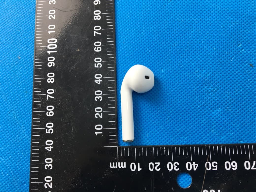
2ARUI-KKSOLL
Jul 25, 2021Bluetooth Wireless Earbuds
Equipment Class
DSS - Part 15 Spread Spectrum Transmitter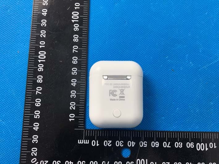
2ARUI-KKSOLR
Jul 25, 2021Bluetooth Wireless Earbuds
Equipment Class
DSS - Part 15 Spread Spectrum Transmitter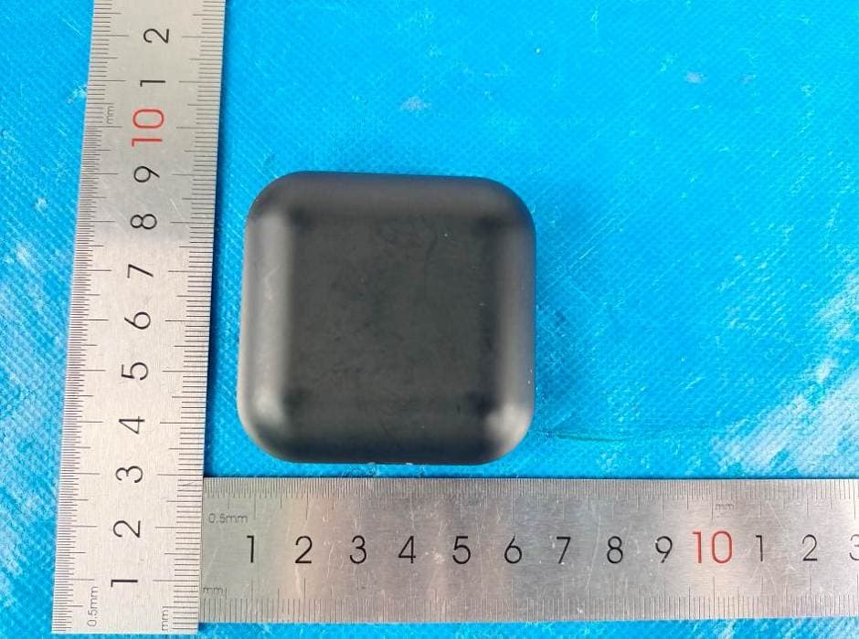
2ARUI-ITAMP
Jul 08, 2021True Wireless Earbuds
Equipment Class
DSS - Part 15 Spread Spectrum Transmitter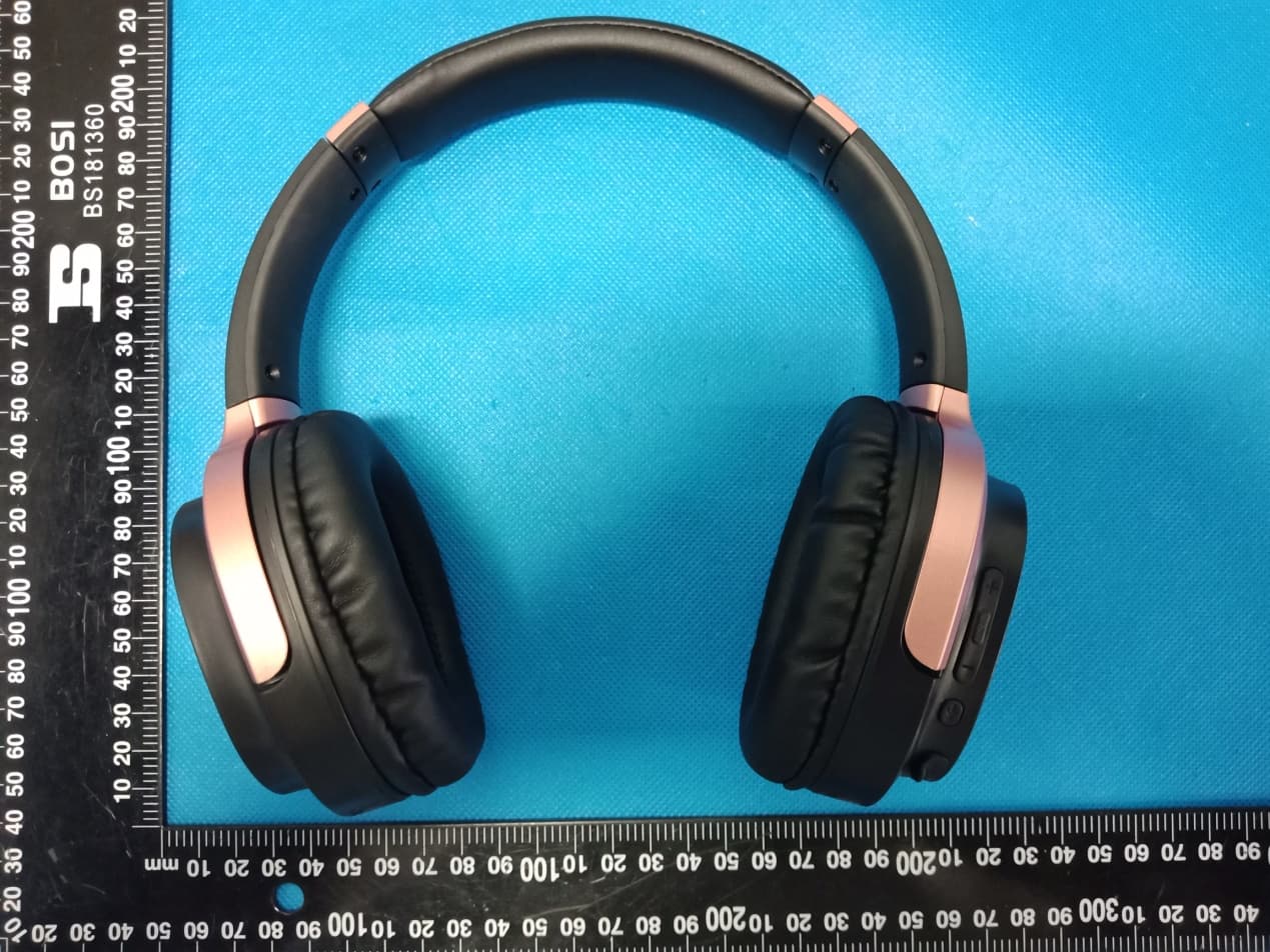
2ARUI-KKWEEN
Jul 07, 2021Bluetooth Headphone
Equipment Class
DSS - Part 15 Spread Spectrum Transmitter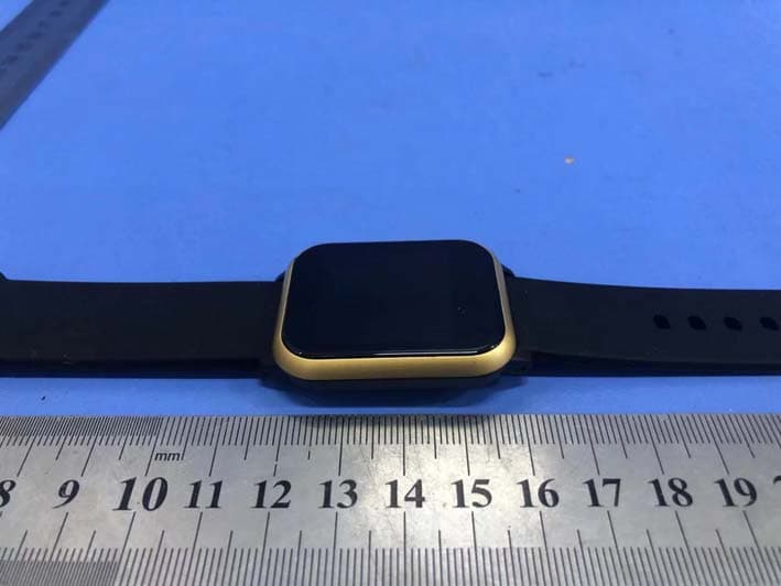
2ARUI-XFIVE21SQ
Apr 28, 2021X-Five Smartwatch
Equipment Class
DTS - Digital Transmission System