2AS22-LUMACH2CBRS Radio Module
Skylark Wireless LLC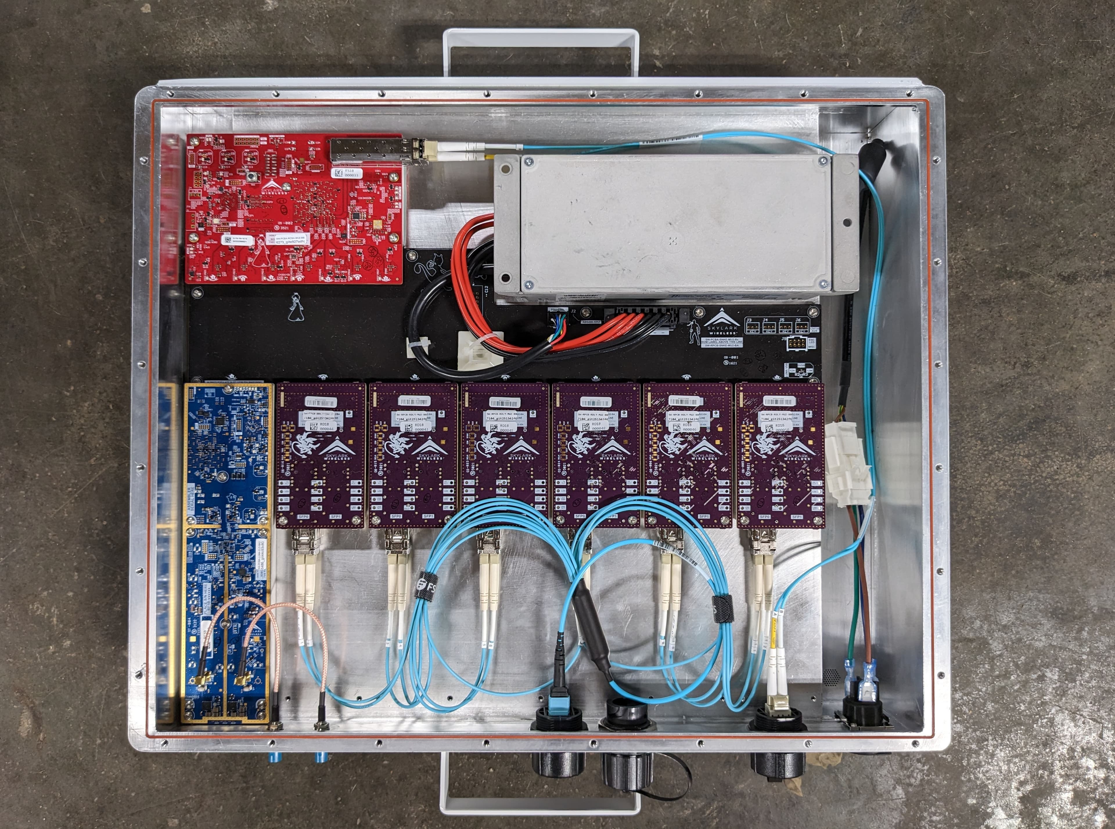
Click to zoom
Application Details
- Equipment Class
- CBD - Citizens Band Category A and B Devices
- Date of Grant
- Oct 03, 2023
- Application Purpose
- Original Equipment
- Date of Application
- Jul 30, 2023
- Equipment Note
- CBRS Radio Module
- Frequency Range
- 3550.00000000 - 3700.00000000
- Company
- Skylark Wireless LLC
- Country
- United States
Documents & Files
Document Text
Text extracted from the exhibit documents filed with the FCC. Open a document above to read the original.
Attestation Statements
June 9, 2023 Element Materials Technology Washington DC LLC Certification Body Division 7185 Oakland Mills Road Columbia, MD 21046 RE: Certification For US Agent Accepting Service of Process This letter is to confirm that the below U.S. Agent is accepting the responsibility to act as the U.S. based Agent for service of process as required by 47CFR §2.911(d)(7) for Skylark Wireless, LLC. DESIGNATED U.S. AGENT INFORMATION FCC Registration Number (FRN): 0023950942 Company Name: Skylark Wireless, LLC Contact Person: Clayton W. Shepard Company Address: 4011 Garrott St, Houston, TX 77006 Telephone No: 832-899-5275 Email: [email protected] The applicant accepts and acknowledges the obligation to maintain this agent in the US for no less than one year after terminating all marketing and importation OR the conclusion of any Commission- related proceeding involving the equipment. The Applicant further acknowledges their responsibility to inform the FCC whenever the Designated U.S. Agent information changes. The agent is not affiliated with a test lab or TCB. APPLICANT INFORMATION FCC Registration Number (FRN): 0023950942 Company Name: Skylark Wireless, LLC Grantee Code: 2AS22 Contact Person: Ryan E. Guerra Company Address: 4011 Garrott St, Houston, TX 77006 Telephone No: 832-701-0253;413 Email: [email protected] Skylark Wireless, LLC Skylark Wireless, LLC Clayton W. Shepard Ryan E. Guerra CTO CEO June 9, 2023 June 9, 2023 DocuSign Envelope ID: 33B553DE-101D-491E-A025-90762B4857B1
Attestation Statements
June 9, 2023 Element Materials Technology Washington DC LLC Certification Body Division 7185 Oakland Mills Road Columbia, MD 21046 RE: Covered List Equipment for FCC ID: 2AS22-LUMACH2 Per 47 CRF Section 2.911(d)(5)(i) Skylark Wireless, LLC (“the applicant”) certifies that the equipment for which authorization is sought is not “covered” equipment prohibited from receiving an equipment authorization pursuant to section 2.903 of the FCC rules. Note: If the equipment for which the applicant seeks authorization IS produced by any of the entities identified on the current Covered List, including affiliates or subsidiaries of the named companies, the applicant must include an explanation on why the equipment is not “covered” equipment. Additional Explanation: N/A Per 47 CRF Section 2.911(d)(5)(ii) Skylark Wireless, LLC (“the applicant”) certifies that, as of the date of the filing of the application, the applicant ☐ IS / IS NOT identified on the Covered List as an entity producing “covered” equipment. Sincerely, Ryan E. Guerra Skylark Wireless LLC CEO DocuSign Envelope ID: 33B553DE-101D-491E-A025-90762B4857B1
Attestation Statements
August 1, 2023 Element Materials Technology Washington DC LLC 7185 Oakland Mills Road Columbia, MD 21046 RE: Anti-Drug Abuse Attestation for FCC ID: 2AS22-LUMACH2 To whom it may concern: We also hereby certify that no party to this application is subject to a denial of benefits, including FCC benefits, pursuant to Section 5301 of the Anti-Drug Abuse Act of 1988, 21 U.S. C. 862. Sincerely, Ryan E. Guerra Skylark Wireless LLC CEO DocuSign Envelope ID: 0A43911C-739E-459B-9B89-85D9497581DE
Cover Letter(s)
July 7, 2023 Federal Communications Commission Office of Engineering and Technology Laboratory Division 7435 Oakland Mills Road Columbia, MD 21046 RE: Request for Confidentiality for FCC ID: 2AS22-LUMACH2 To whom it may concern, We seek a limited split modular approval for our module. Below is a justification, based on the requirements for modular transmitters, as to why this classification is appropriate for our device. Modular Approval Requirements Item Requirement Meets Justification 1 The radio elements must have the radio frequency circuitry shielded. Physical components and tuning capacitor(s) may be located external to the shield, but must be on the module assembly. Yes The module has an integrated heatsink and RF shield on the component side, and there are no RF tracks or components on the solder side. Please refer to the block diagram and photos associated with this application. 2 The module must have buffered modulation/data inputs to ensure that the device will comply with Part 15 requirements with any type of input signal. Yes The FPGA on the module has a built-in I/O and logic buffer. 3 The module must contain power supply regulation on the module. Yes The device has integrated power supply regulation for all voltages on the module. 4 The module must contain a permanently attached antenna, or contain a unique antenna connector, and be marketed and operated only with specific antenna(s), per §§ 15.203, 15.204(b), 15.204(c), 15.212(a), 2.929(b). No As a split-modular transmitter, the module is only authorized for operation within a specific host enclosure. In said enclosure (which includes the only antenna with which the product is marketed and operated), the module is mated to a specific antenna, and therefore the modular transmitter meets all the applicable part 15 requirements under the operating conditions in which the transmitter will be used. 5 The module must demonstrate compliance in a stand-alone configuration. No As a split-modular transmitter, the device is not capable of demonstrating compliance in a stand-alone configuration, nor is it required to do so. See Requirement 3 in the “Split Modular Approval Requirements” section of this letter for more detail. DocuSign Envelope ID: ADC893CB-F787-4021-862A-ED371D7709B7 6 The module must be labeled with its permanently affixed FCC ID label, or use an electronic display (see KDB Publication 784748). Yes The module will have an FCC ID label permanently affixed as illustrated in the labeling exhibit attached with this submission. The module will always be inside another enclosure during actual use. The host device will have “Contains FCC ID 2AS22- LUMACH2” 7 The module must comply with all specific rules applicable to the transmitter, including all the conditions provided in the integration instructions by the grantee. Yes The module will only be integrated by the manufacturer into the specific hosts included in this equipment authorization application. As such, the test report attached with this submission serves as sufficient proof of compliance with the applicable rules (47 CFR Parts 15 and 96). 8 The module must comply with RF exposure requirements. Yes The module is compliant with all applicable RF exposure requirements. RF Exposure is addressed in the RF exposure exhibit included in this submission. Split Modular Approval Requirements Item Requirement Meets Justification 1 Only the radio front-end must be shielded. The physical components, crystal, and tuning capacitor(s) may be located external to the shielded radio elements. The interface between the split sections of the modular system must be digital, with a minimum signaling amplitude of 150 mV peak-to-peak. Yes The radio front end for the module is shielded as noted above. Additional shielding is provided by the host enclosure. The interface between the split sections is comprised of: • Two differential pairs which encapsulate radio packets in and out of the onboard baseband processor. For radio transmission, one of the differential pairs sends the onboard processing element which transforms the encoded user data into time synchronized I/Q data and relays it to the radio integrated circuit. Receive data is performed in the reverse order and sent up the second differential pair. • There are 13 signals which are used to configure the processing element from the host and subsequently are used for out-of-band communications. • There are 7 signals which are used to communicate with and enable the onboard power subsystem. DocuSign Envelope ID: ADC893CB-F787-4021-862A-ED371D7709B7 • One differential pair brings in a low noise system-synchronous clock for the radio and the processing element. • The minimum signaling amplitude of these differential pairs is 150mV peak-to-peak. 2 Control information and other data may be exchanged between the transmitter control elements and the radio front-end. Yes As detailed in item 1 directly above, the interface between the radio front end and the onboard processor includes I/Q baseband data and control signaling. 3 The sections of a split-modular transmitter are installed for testing on a host platform that is representative of the platform(s) intended for use. It is the responsibility of the applicant to demonstrate the appropriateness of the test platform for compliance to a widespread range of common host platforms, i.e., not restricted to a specific host. For example, compliance may be demonstrated on an open (not within a specific host enclosure) reference-design circuit board, to demonstrate conformity independent of the host environment. Therefore, note that when compliance is tested with the module enclosed in a specific host, then the split module must be limited. No Compliance testing for this module requires enclosure within a specific host (described in other portions of this application). Therefore, per the text of the requirement as written in KDB 996369, this module must be classified as a limited split module. When e…
Text truncated - open the document above for the full version.
Cover Letter(s)
July 21, 2023 Federal Communications Commission Office of Engineering and Technology Laboratory Division 7435 Oakland Mills Road Columbia, MD 21046 RE: Request for Confidentiality for FCC ID: 2AS22-LUMACH2 To whom it may concern, Pursuant to the provisions of Sections 0.457 and 0.459 of the Commission’s Rules (CFR 47), Skylark Wireless, LLC hereby requests Long-Term Confidentiality treatment of the following attachments by the Commission: • Schematic Diagram • Block Diagram • Part List • Operational Description & Tune-up Procedure • Internal Photos • User Manual The above-mentioned documents contain detailed system and equipment descriptions and are considered as proprietary information not customarily released to the public. The public disclosure of these matters might be harmful to the Applicant and provide unjustified benefits to its competitors. Regarding the Long-Term Confidentiality request for the User Manual, Skylark attests that all sales of the non-consumer device will be under NDA, including third party sales, and that the final user of the device will be subject to the NDA as required by the special conditions of KDB 726290 D01 Section II(3)(c). Furthermore, as required by Section II(3)(c)(4) of the KDB, a sample of the NDA between the grantee and the purchaser has been included in this filing. Regarding the Long-Term Confidentiality request for the Internal Photos, the following points illustrate how the product satisfies the conditions outlined in KDB 726290 D01 Sections II(3)(a) and II(3)(c)(2): • II(3)(a)(1): The circuit board and internal components are not accessible to users due to the use of non-standard screws on the host enclosure. • II(3)(a)(2): The device is not accessible to the public as it is only intended to be mounted on large towers, many of which will likely be in a fenced enclosure. Therefore, the device will only be serviceable by professional designated technicians, all of whom will be DocuSign Envelope ID: 3920A1DB-4E34-43A4-A8F5-5E313BEA17EC under NDA with the grantee to restrict the disclosure of proprietary information, including internal photos. • II(3)(c)(2): As outlined above, both the nonstandard screws as well as the deployment locations of the product will serve to restrict public access to the products, which are only serviceable by professional designated technicians. This is especially true given the device’s classification as a Class B CBSD, which requires installation to be performed only by Certified Professional Installers. Additionally, pursuant to Public Notice DA 04-1705 of the Commission’s Policy, we hereby request a 180-day period of Short-Term Confidentiality for the following attachments: • External Photos • Test Setup Photos The short-term confidentiality period will give Skylark Wireless, LLC temporary confidentiality of commercially sensitive information prior to product release. Sincerely, Ryan E. Guerra Skylark Wireless LLC CEO DocuSign Envelope ID: 3920A1DB-4E34-43A4-A8F5-5E313BEA17EC
External Photos
Rear View of Antenna Assembly Front View of Antenna Assembly
ID Label/Location Info
FCC ID Label and Location Label TypeLabelLocation ModuleLabel is silkscreened onto the module during the manufacturing process – see Theory of Operations Exhibit for specific position Host EnclosureLabel is attached to side of host enclosure by adhesive material.
RF Exposure Info
FCC ID: 2AS22-LUMACH2 MAXIMUM PERMISSIBLE EXPOSURE REPORT Approved by: Technical Manager Test Report S/N: Test Dates: EUT Type: Page 1 of 6 1M2305080068-03.2AS22 05/08/2023 – 05/19/2023 Category B CBRS Base Station V 9.0 02/01/2019 Unless otherwise specified, no part of this report may be reproduced or utilized in any part, form or by any means, electronic or mechanical, including photocopying and microfilm, without written permission from Element. If you have any questions about this or have an inquiry about obtaining additional rights to this report or assembly of contents thereof, please contact [email protected]. Applicant Name: Skylark Wireless, LLC 4011 Garrott St Houston, TX 77006 USA Date of Testing: 05/08/2023 – 05/19/2023 Test Report Issue Date: 07/13/2023 Test Site/Location: Element Lab. Columbia, MD, USA Test Report Serial No.: 1M2305080068-03.2AS22 FCC ID: 2AS22-LU MA CH2 APPLICANT: Skylark Wireless, LLC EUT Type: Category B CBRS Base Station FCC Classification: Category B Citizens Band Radio Service Devices (CBSD) FCC Rule Part: FCC Part 1 (§1.1310) and Part 2 (§2.1091) Test Procedure(s): KDB 447498 D01 This equipment has been shown to be capable of compliance with the applicable technical standards as indicated in the measurement report and was tested in accordance with the measurement procedures specified in FCC KDB 447498 D01. Test results reported herein relate only to the item(s) tested. I attest to the accuracy of data. All measurements reported herein were performed by me or were made under my supervision and are correct to the best of my knowledge and belief. I assume full responsibility for the completeness of these measurements and vouch for the qualifications of all persons taking them. RJ Ortanez Executive Vice President ELEMENT WASHINGTON DC LLC 7185 Oakland Mills Road, Columbia, MD 21046 USA Tel. 410.290.6652 / Fax 410.290.6654 http://www.element.com RF EXPOSURE EVALUATION Maximum Permissible Exposure (MPE) FCC ID: 2AS22-LUMACH2 MAXIMUM PERMISSIBLE EXPOSURE REPORT Approved by: Technical Manager Test Report S/N: Test Dates: EUT Type: Page 2 of 6 1M2305080068-03.2AS22 05/08/2023 – 05/19/2023 Category B CBRS Base Station V 9.0 02/01/2019 Unless otherwise specified, no part of this report may be reproduced or utilized in any part, form or by any means, electronic or mechanical, including photocopying and microfilm, without written permission from Element. If you have any questions about this or have an inquiry about obtaining additional rights to this report or assembly of contents thereof, please contact [email protected]. T A B L E O F C O N T E N T S 1.0 RF EXPOSURE EVALUATION – MAXIMUM PERMISSIBLE EXPOSURE (MPE) ........................ 3 1.1 Introduction ............................................................................................................................................ 3 1.2 EUT Description ..................................................................................................................................... 3 1.3 Procedure .............................................................................................................................................. 4 2.0 CONCLUSION ................................................................................................................................. 6 FCC ID: 2AS22-LUMACH2 MAXIMUM PERMISSIBLE EXPOSURE REPORT Approved by: Technical Manager Test Report S/N: Test Dates: EUT Type: Page 3 of 6 1M2305080068-03.2AS22 05/08/2023 – 05/19/2023 Category B CBRS Base Station V 9.0 02/01/2019 Unless otherwise specified, no part of this report may be reproduced or utilized in any part, form or by any means, electronic or mechanical, including photocopying and microfilm, without written permission from Element. If you have any questions about this or have an inquiry about obtaining additional rights to this report or assembly of contents thereof, please contact [email protected]. 1.0 R F E X P O S U R E E V A L U A T I O N – M A X I M U M P E R M I S S I B L E E X P O S U R E ( M P E ) 1.1 Introduction This document is prepared to show compliance with the RF Exposure requirements as required in §1.1310 of the FCC Rules and Regulations and RSS-102 of Industry Canada. The limit for Maximum Permissible Exposure (MPE), specified in FCC §1.1310, is listed in Table 1-1. According to FCC §1.1310 and RSS-102: the criteria listed in the following table shall be used to evaluate the environmental impact of human exposure to radio-frequency (RF) radiation as specified in §1.1307(b). Frequency Range (MHz) Electric Field Strength (V/m) Magnetic Field Strength (A/m) Power Density (mW/cm 2 ) Average Time (Minutes) (A) Limits For Occupational / Control Exposures (f = frequency) 30-300 61.4 0.163 1.0 6 300-1500 ... ... f/300 6 1500-100,000 ... ... 5.0 6 (B) Limits For General Population / Uncontrolled Exposure (f = frequency) 30-300 27.5 0.073 0.2 30 300-1500 ... ... f/1500 30 1500-100,000 ... ... 1.0 30 Table 1-1. Limits for Maximum Permissible Exposure (MPE) 1.2 EUT Description The Skylark Wireless, LLC FCC ID: 2 A S 2 2-L U M A C H 2 is a CBRS Radio Module. It has two antenna ports which transmit simultaneously in the 3550 – 3700 MHz band. Only the highest power mode is assessed for compliance. The EUT is installed in a dedicated chassis and can only operate in the dedicated chassis. FCC ID: 2AS22-LUMACH2 MAXIMUM PERMISSIBLE EXPOSURE REPORT Approved by: Technical Manager Test Report S/N: Test Dates: EUT Type: Page 4 of 6 1M2305080068-03.2AS22 05/08/2023 – 05/19/2023 Category B CBRS Base Station V 9.0 02/01/2019 Unless otherwise specified, no part of this report may be reproduced or utilized in any part, form or by any means, electronic or mechanical, including photocopying and microfilm, without written permission from Element. If you have any questions about this or have an inquiry about obtaining additional rights to this report or assembly of contents thereof, please contact ct.info@…
Text truncated - open the document above for the full version.
Test Report
FCC ID: 2AS22-LUMACH2 PART 96 MEASUREMENT REPORT Approved by: Technical Manager Test Report S/N: Test Dates: EUT Type: Page 1 of 144 1M2305080068-01.2AS22 05/08/2023 – 7/13/2023 CBRS Radio Module V3.0 1/6/2022 Unless otherwise specified, no part of this report may be reproduced or utilized in any part, form or by any means, electronic or mechanical, including photocopying and microfilm, without permission in writing from Element. If you have any questions about this or have an inquiry about obtaining additional rights to this report or assembly of contents thereof, please contact [email protected]. Applicant Name: Skylark Wireless, LLC 4011 Garrott St. Houston, TX 77006 USA Date of Testing: 05/08/2023 – 7/13/2023 Test Report Issue Date: 07/14/2023 Test Site/Location: Element Lab., Columbia, MD, USA Test Report Serial No.: 1M2305080068-01.2AS22 FCC ID: 2AS22-LUMACH2 APPLICANT: Skylark Wireless, LLC Application Type: Certification Model: LUMACH2 EUT Type: CBRS Radio Module FCC Classification: Category B Citizens Band Radio Service Devices (CBSD) FCC Rule Part(s): 96 Test Procedure(s): ANSI C63.26-2015, KDB 940660 D01 v03 This equipment has been shown to be capable of compliance with the applicable technical standards as indicated in the measurement report and was tested in accordance with the measurement procedures specified in §2.947. Test results reported herein relate only to the item(s) tested. I attest to the accuracy of data. All measurements reported herein were performed by me or were made under my supervision and are correct to the best of my knowledge and belief. I assume full responsibility for the completeness of these measurements and vouch for the qualifications of all persons taking them. RJ Ortanez Executive Vice President ELEMENT WASHINGTON DC LLC 7185 Oakland Mills Road, Columbia, MD 21046 USA Tel. 410.290.6652 / Fax 410.290.6654 http://www.element.com Part 96 MEASUREMENT REPORT FCC ID: 2AS22-LUMACH2 PART 96 MEASUREMENT REPORT Approved by: Technical Manager Test Report S/N: Test Dates: EUT Type: Page 2 of 144 1M2305080068-01.2AS22 05/08/2023 – 7/13/2023 CBRS Radio Module V3.0 1/6/2022 Unless otherwise specified, no part of this report may be reproduced or utilized in any part, form or by any means, electronic or mechanical, including photocopying and microfilm, without permission in writing from Element. If you have any questions about this or have an inquiry about obtaining additional rights to this report or assembly of contents thereof, please contact [email protected]. TABLE OF CONTENTS 1.0 INTRODUCTION ........................................................................................................................................... 4 1.1 Scope ................................................................................................................................................................. 4 1.2 Element Test Location ........................................................................................................................................ 4 1.3 Test Facility / Accreditations ............................................................................................................................... 4 2.0 PRODUCT INFORMATION ........................................................................................................................... 5 2.1 Equipment Description ....................................................................................................................................... 5 2.2 Device Capabilities ............................................................................................................................................. 5 2.3 Test Configuration .............................................................................................................................................. 5 2.4 Software and Firmware ...................................................................................................................................... 5 2.5 EMI Suppression Device(s)/Modifications .......................................................................................................... 5 3.0 DESCRIPTION OF TESTS ........................................................................................................................... 6 3.1 Measurement Procedure .................................................................................................................................... 6 3.2 Radiated Power and Radiated Spurious Emissions ........................................................................................... 6 4.0 MEASUREMENT UNCERTAINTY ................................................................................................................ 8 5.0 TEST EQUIPMENT CALIBRATION DATA ................................................................................................... 9 6.0 SAMPLE CALCULATIONS ......................................................................................................................... 10 7.0 TEST RESULTS .......................................................................................................................................... 11 7.1 Summary .......................................................................................................................................................... 11 7.2 Conducted Output Power/EIRP Data ............................................................................................................... 13 7.3 Occupied Bandwidth ........................................................................................................................................ 32 7.4 Conducted Power / EIRP Per 10MHz ............................................................................................................... 51 7.5 Power Spectral Density .........................................................................................................…
Text truncated - open the document above for the full version.
Test Report
FCC ID: 2AS22-LUMACH2 PART 96 MEASUREMENT REPORT Approved by: Technical Manager Test Report S/N: Test Dates: EUT Type: Page 105 of 144 1M2305080068-01.2AS22 05/08/2023 – 7/13/2023 CBRS Radio Module V3.0 1/6/2022 Unless otherwise specified, no part of this report may be reproduced or utilized in any part, form or by any means, electronic or mechanical, including photocopying and microfilm, without permission in writing from Element. If you have any questions about this or have an inquiry about obtaining additional rights to this report or assembly of contents thereof, please contact [email protected]. Plot 7.157. Peak to Average Power Ratio Plot (10MHz, QPSK – Mid Channel) – Ch.B Plot 7.158. Peak to Average Power Ratio Plot (10MHz, 16QAM – Mid Channel) – Ch.B FCC ID: 2AS22-LUMACH2 PART 96 MEASUREMENT REPORT Approved by: Technical Manager Test Report S/N: Test Dates: EUT Type: Page 106 of 144 1M2305080068-01.2AS22 05/08/2023 – 7/13/2023 CBRS Radio Module V3.0 1/6/2022 Unless otherwise specified, no part of this report may be reproduced or utilized in any part, form or by any means, electronic or mechanical, including photocopying and microfilm, without permission in writing from Element. If you have any questions about this or have an inquiry about obtaining additional rights to this report or assembly of contents thereof, please contact [email protected]. Plot 7.159. Peak to Average Power Ratio Plot (10MHz, 64QAM – Mid Channel) – Ch.B Plot 7.160. Peak to Average Power Ratio Plot (10MHz, 256QAM – Mid Channel) – Ch.B FCC ID: 2AS22-LUMACH2 PART 96 MEASUREMENT REPORT Approved by: Technical Manager Test Report S/N: Test Dates: EUT Type: Page 107 of 144 1M2305080068-01.2AS22 05/08/2023 – 7/13/2023 CBRS Radio Module V3.0 1/6/2022 Unless otherwise specified, no part of this report may be reproduced or utilized in any part, form or by any means, electronic or mechanical, including photocopying and microfilm, without permission in writing from Element. If you have any questions about this or have an inquiry about obtaining additional rights to this report or assembly of contents thereof, please contact [email protected]. 7.7 Spurious and Harmonic Emissions at Antenna Terminal Test Overview The level of the carrier and the various conducted spurious and harmonic frequencies is measured by means of a calibrated spectrum analyzer. The spectrum is scanned from the lowest frequency generated in the equipment up to a frequency including its 10 th harmonic. All out of band emissions are measured with a spectrum analyzer connected to the antenna terminal of the EUT while the EUT is operating at its maximum duty cycle, at maximum power, and at the appropriate frequencies. All data rates were investigated to determine the worst-case configuration. All modes of operation were investigated and the worst-case configuration results are reported in this section. The conducted power of any emissions below 3530 MHz or above 3720 MHz shall not exceed -40 dBm/Mhz. Test Procedure Used ANSI C63.26-2015 – Section 5.7.4 Test Settings 1. Start frequency was set to 30MHz and stop frequency was set to at least 10 * the fundamental frequency (separated into at least two plots per channel) 2. Detector = RMS 3. Trace mode = Max Hold 4. Sweep time = auto couple 5. The trace was allowed to stabilize 6. Please see test notes below for RBW and VBW settings Test Setup The EUT and measurement equipment were set up as shown in the diagram below. Figure 7-6. Test Instrument & Measurement Setup Test Notes 1. Compliance with the applicable limits is based on the use of measurement instrumentation employing a resolution bandwidth of 1 MHz. 2. The Plots in this section have a 3dB correction applied to the individual plots to address the MIMO requirements in ANSI C63.26 3. Unwanted emissions between 3510MHz and 3530MHz, as well as between 3720 MHz and 3740 MHz, are observed and reported in section 7.8. FCC ID: 2AS22-LUMACH2 PART 96 MEASUREMENT REPORT Approved by: Technical Manager Test Report S/N: Test Dates: EUT Type: Page 108 of 144 1M2305080068-01.2AS22 05/08/2023 – 7/13/2023 CBRS Radio Module V3.0 1/6/2022 Unless otherwise specified, no part of this report may be reproduced or utilized in any part, form or by any means, electronic or mechanical, including photocopying and microfilm, without permission in writing from Element. If you have any questions about this or have an inquiry about obtaining additional rights to this report or assembly of contents thereof, please contact [email protected]. Plot 7.161. Conducted Spurious Plot (10MHz QPSK, Low Channel – Ch.A) Plot 7.162. Conducted Spurious Plot (10MHz QPSK, Low Channel – Ch.A) FCC ID: 2AS22-LUMACH2 PART 96 MEASUREMENT REPORT Approved by: Technical Manager Test Report S/N: Test Dates: EUT Type: Page 109 of 144 1M2305080068-01.2AS22 05/08/2023 – 7/13/2023 CBRS Radio Module V3.0 1/6/2022 Unless otherwise specified, no part of this report may be reproduced or utilized in any part, form or by any means, electronic or mechanical, including photocopying and microfilm, without permission in writing from Element. If you have any questions about this or have an inquiry about obtaining additional rights to this report or assembly of contents thereof, please contact [email protected]. Plot 7.163. Conducted Spurious Plot (10MHz QPSK, Low Channel – Ch.A) Plot 7.164. Conducted Spurious Plot (10MHz QPSK, Low Channel – Ch.A) FCC ID: 2AS22-LUMACH2 PART 96 MEASUREMENT REPORT Approved by: Technical Manager Test Report S/N: Test Dates: EUT Type: Page 11…
Text truncated - open the document above for the full version.
Contact Information
Applicant
Ryan Guerra
Test Firm
Element Materials Technology Washington DC LLCZach Keyser
[email protected]1111111111
Technical Specifications
| # | Rule Parts | Frequency Range | Power Output | Emission | Tolerance |
|---|---|---|---|---|---|
| 8 | 96 | 3.55 GHz - 3.70 GHz | 2.851 W | 35M6W7D | 2.5 ppm |