2AS2I120GHAED TRAINER
SHENZHEN XFT MEDICAL LIMITED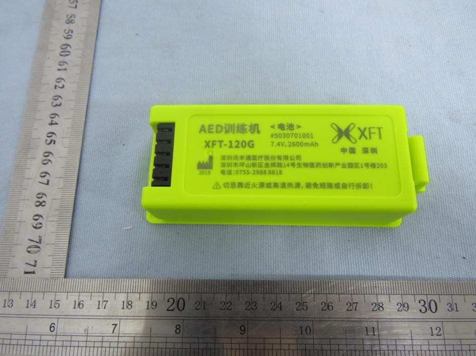
Click to zoom
Application Details
- Equipment Class
- DTS - Digital Transmission System
- Date of Grant
- Jan 07, 2020
- Application Purpose
- Original Equipment
- Date of Application
- Jan 07, 2020
- Equipment Note
- AED TRAINER
- Frequency Range
- 2402.00000000 - 2480.00000000
- Company
- SHENZHEN XFT MEDICAL LIMITED
- Country
- China
Documents & Files
Document Text
Text extracted from the exhibit documents filed with the FCC. Open a document above to read the original.
Users Manual
1 / 20 Thank you for purchasing XFT-120GAED Trainer Please read the instruction manual carefully and thoroughly before operating this device. Also please keep it available for future reference. 2 / 20 Content 1. Product Introduction.........................................................................................................................................................3 2. Product Illustration...........................................................................................................................................................3 2.1 The Trainer.............................................................................................................................................................4 2.2 The Trainer Display Screen....................................................................................................................................6 2.3 The Remote Control...............................................................................................................................................7 2.4Accessories...........................................................................................................................................................10 3.Operating Instruction.......................................................................................................................................................11 3.1 Preparation........................................................................................................................................................... 11 3.2 Power on and select training mode......................................................................................................................12 3.3 Connecting Electrode Pad....................................................................................................................................12 3.4 Follow the voice prompts.....................................................................................................................................13 3.5 Setting Interface...................................................................................................................................................13 3.6 Shutdown............................................................................................................................................................. 16 4. Product maintenance...................................................................................................................................................... 16 4.1 The trainer maintenance.......................................................................................................................................16 4.2 Electrode maintenance.........................................................................................................................................16 4.3 Battery Disassembly and Maintenance................................................................................................................16 4.4 Working Condition and Storage Condition......................................................................................................... 18 5. Specification and Product Contents................................................................................................................................18 5.1 The Trainer...........................................................................................................................................................18 5.2 Remote Control....................................................................................................................................................18 5.3 Product Contents..................................................................................................................................................19 6.After-sales Service..........................................................................................................................................................20 3 / 20 List of Symbols Date of Manufacture Manufacturer This product must not be disposed of with other household waste Refer to user manual Serial Number Fragile Keep upward Keep dry Temperature limit Humidity limitation Atmospheric pressure limitation 1. Product Introduction XFT-120G AED (Automated External Defibrillator) Trainer is specifically designed to train first-aid personnel before they use a real clinical AED. The AED Trainer completely simulates the operation of AED in the training guide and training program, but does not deliver high voltage electric shock, protecting the safety of trainees. It can be used to help first-aid personnel get familiar with AED and master some necessary basic operating skills of using AED in the first aid process. Before using an AED, first-aid personnel should first complete training courses on how to respond calmly in a real accident. These training courses also include learning how to use an AED Trainer. A trained first-aid personnel should know how to assess a patient's condition, such as loss of consciousness, respiratory arrest, cardiac arrest, etc., and should be proficient in CPR procedures and related medical procedures. 2. Product Illustration XFT-120G AED Trainer consists of the Trainer, Remote Control, Electrode Pads, Pad Sensors, Instruction Manual, PowerAdapter, and Storage Bag. 4 / 20 2.1 The Trainer 2.1.1. Front View Fig. 1 Front ViewFig.2 Open the Cover 1) Handle 2) Cover When Open the cover, the AED Trainer will be turned one; when close the cover, the AED Trainer will be turned off. 3) USB Interface It is used to upgrade the software. 4) Electrode Socket: It is used to connect the electrode pad. 5) Display Screen When the Trainer is working, the screen will display the working status. 6) Power Button Turn on the trainer by opening the cover, during this state, press the Powerbutton to shut down the Trainer 7) Sho…
Text truncated - open the document above for the full version.
External Photos
FCC ID: 2AS2I120GH External photo FCC ID: 2AS2I120GH FCC ID: 2AS2I120GH FCC ID: 2AS2I120GH FCC ID: 2AS2I120GH FCC ID: 2AS2I120GH FCC ID: 2AS2I120GH
ID Label/Location Info
FCC ID: 2AS2I120GH Label & locaton Size: 100mm * 48mm
Internal Photos
FCC ID: 2AS2I120GH Internal photo FCC ID: 2AS2I120GH FCC ID: 2AS2I120GH FCC ID: 2AS2I120GH FCC ID: 2AS2I120GH BT Antenna BT Chip FCC ID: 2AS2I120GH FCC ID: 2AS2I120GH
Operational Description
SHENZHEN XFT MEDICAL LIMITED Declaration concerning Antenna Specification It is hereby declared that the product Model No.: XFT-120G FCC ID: 2AS2I120GH fulfills the requirement in FCC test relating to the antenna type. The device specified above confirms to the FCC recommendations for PCB antenna type(s) described below: Model No. of antenna: BT Antenna Type of antenna: permanently attached (PCB antenna) Gain of the antenna: 0.993 dBi Frequency range: 2402-2480 MHz The mounting of the antenna is fixed to the radio module and no other antenna should be used. Company name: SHENZHEN XFT MEDICAL LIMITED Address: Room 203 Building 1, Biomedicine Innovations Industrial Park, #14 Jinhui Road, Pingshan District, City: Shenzhen ZIP / Postal code: N/A Country: China Place: Zuen Tan Date: 2020-01-03 Signature:
RF Exposure Info
Dongguan Nore Testing Center Co., Ltd. Report No.: NTC1909219F-1 FCC ID: 2AS2I120GH RF EXPOSURE EVALUATION EUT Specification EUT AED TRAINER Frequency band (Operating) WLAN: 2.412GHz ~ 2.462GHz WLAN: 5.18GHz ~ 5.32GHz / 5.50GHz ~ 5.70GHz WLAN: 5.745GHz ~ 5825GHz Others(Bluetooth: 2.402GHz ~ 2.480GHz) Device category Portable (<20cm separation) Mobile (>20cm separation) Others ___ Antenna diversity Single antenna Multiple antennas Tx diversity Rx diversity Tx/Rx diversity Max. output power -9.026dBm(0.13mW) Antenna gain 0.993dBi Evaluation applied MPE Evaluation SAR Evaluation Standard Requirement Portable Device According to §15.247(i) and §1.1307b(1), systems operating under the provisions of this section shall be operated in a manner that ensures that the public is not exposed to radio frequency energy levels in excess of the Commission’s guidelines. See KDB 447498 D01 General RF Exposure Guidance v05, section 4.3.1. The 1-g and 10-g SAR test exclusion thresholds for 100 MHz to 6 GHz at test separation distances ≤ 50 mm are determined by: [(max. power of channel, including tune-up tolerance, mW)/(min. test separation distance, mm)] ·[√f(GHz)] ≤ 3.0 for 1-g SAR and ≤ 7.5 for 10-g extremity SAR, 16 where ·f(GHz) is the RF channel transmit frequency in GHz ·Power and distance are rounded to the nearest mW and mm before calculation17 ·The result is rounded to one decimal place for comparison The test exclusions are applicable only when the minimum test separation distance is ≤ 50 mm and for transmission frequencies between 100 MHz and 6 GHz. When the minimum test separation distance is < 5 mm, a distance of 5 mm is applied to determine SAR test exclusion. Dongguan Nore Testing Center Co., Ltd. Report No.: NTC1909219F-1 FCC ID: 2AS2I120GH Measurement Result Channel Channel Frequency (MHz) Max Output power (dBm) Max Output power (mW) Calculati on Value (Note 1) Threshold Value GFSK Low 2402 -9.026 0.125 0.039 3.0 Middle 2440 -10.032 0.099 0.031 3.0 High 2480 -10.650 0.086 0.027 3.0 Note 1: Calculation Value =[(max. power of channel, mW)/(min. test separation distance, mm)] ·[√f(GHz)]. Fox example: 0.125/5*√2.402=0.039 ≤ 3.0 According to KDB447498 D01 V06, threshold at which no SAR required is ≤3.0 for 1-g SAR, separation distance is 5mm, and no simultaneous SAR measurement is required.
Test Report
Dongguan Nore Testing Center Co., Ltd. Report No.: NTC1909219FV00 FCC ID: 2AS2I120GH Page 2 of 32 Table of Contents 1. GENERAL INFORMATION ................................................................................................ 5 1.1 PRODUCT DESCRIPTION FOR EQUIPMENT UNDER TEST ................................................................. 5 1.2 RELATED SUBMITTAL(S) / GRANT (S) ............................................................................................ 7 1.3 TEST METHODOLOGY .................................................................................................................. 7 1.4 EQUIPMENT MODIFICATIONS ........................................................................................................ 7 1.5 SUPPORT DEVICE ....................................................................................................................... 7 1.6 TEST FACILITY AND LOCATION ..................................................................................................... 8 1.7 DEVIATIONS AND ABNORMALITIES FROM STANDARD CONDITIONS ................................................... 8 1.8 SUMMARY OF TEST RESULTS ....................................................................................................... 9 2. SYSTEM TEST CONFIGURATION .................................................................................. 10 2.1 EUT CONFIGURATION ............................................................................................................... 10 2.2 SPECIAL ACCESSORIES ............................................................................................................. 10 2.3 DESCRIPTION OF TEST MODES ................................................................................................... 10 2.4 EUT EXERCISE ......................................................................................................................... 10 3. CONDUCTED EMISSIONS TEST .................................................................................... 11 3.1 TEST SET-UP (BLOCK DIAGRAM OF CONFIGURATION) ................................................................ 11 3.2 TEST CONDITION ....................................................................................................................... 11 3.3 MEASUREMENT RESULTS .......................................................................................................... 11 4. MAX. CONDUCTED OUTPUT POWER ........................................................................... 12 4.1 MEASUREMENT PROCEDURE ..................................................................................................... 12 4.2 TEST SET-UP (BLOCK DIAGRAM OF CONFIGURATION) ................................................................ 12 4.3 MEASUREMENT RESULTS .......................................................................................................... 12 5. 6DB BANDWIDTH............................................................................................................ 13 5.1 MEASUREMENT PROCEDURE ..................................................................................................... 13 5.2 TEST SET-UP (BLOCK DIAGRAM OF CONFIGURATION) ................................................................ 13 5.3 MEASUREMENT RESULTS .......................................................................................................... 13 6. POWER SPECTRAL DENSITY ....................................................................................... 16 6.1 MEASUREMENT PROCEDURE ..................................................................................................... 16 6.2 TEST SET-UP (BLOCK DIAGRAM OF CONFIGURATION) ................................................................ 16 6.3 MEASUREMENT RESULTS .......................................................................................................... 16 7. BAND EDGE AND CONDUCTED SPURIOUS EMISSIONS ........................................... 19 7.1 REQUIREMENT AND MEASUREMENT PROCEDURE ........................................................................ 19 7.2 TEST SET-UP (BLOCK DIAGRAM OF CONFIGURATION) ................................................................ 19 7.3 MEASUREMENT RESULTS .......................................................................................................... 19 Dongguan Nore Testing Center Co., Ltd. Report No.: NTC1909219FV00 FCC ID: 2AS2I120GH Page 3 of 32 8. RADIATED SPURIOUS EMISSIONS AND RESTRICTED BANDS ................................. 25 8.1 TEST SET-UP (BLOCK DIAGRAM OF CONFIGURATION) ................................................................ 25 8.2 MEASUREMENT PROCEDURE ..................................................................................................... 26 8.3 LIMIT ........................................................................................................................................ 27 8.4 MEASUREMENT RESULTS ................................................................................................. 27 9. ANTENNA APPLICATION ............................................................................................... 31 9.1 ANTENNA REQUIREMENT............................................................................................................ 31 9.2 MEASUREMENT RESULTS .......................................................................................................... 31 10. TEST EQUIPMENT LIST ................................................................................................ 32 Dongguan Nore Testing Center Co., Ltd. Report No.: NTC1909219FV00 FCC ID: 2AS2I120GH Page 4 of 32 Revision History of This Test Report Report Number Description Issued Date NTC1909219FV00 Initial Issue 2019-11-26 Dongguan Nore Testing Center Co., Ltd. Report No.: NTC1909219FV00 FCC ID: 2AS2I120GH Page 5 of 32 1. GENERAL INFORMATION 1.1 Product Description…
Text truncated - open the document above for the full version.
Test Setup Photos
FCC ID: 2AS2I120GH Test photo Radiated emission Below 30MHz 30MHz-1GHz FCC ID: 2AS2I120GH Above 1GHz
Contact Information
Applicant
xiaoying Jiang
Test Firm
Dongguan NTC CO., Ltd.Jees Hong
[email protected]+86-769-22022444
Technical Specifications
| # | Rule Parts | Frequency Range | Power Output |
|---|---|---|---|
| 1 | 15C | 2.40 GHz - 2.48 GHz | 130.00 µW |
Other Applications from SHENZHEN XFT MEDICAL LIMITED

2AS2I2003EA
Nov 30, 2020Nerve and Muscle Stimulator
Equipment Class
DTS - Digital Transmission System
2AS2I2003E
Nov 30, 2020Nerve and Muscle Stimulator
Equipment Class
DTS - Digital Transmission System