2AS3B-PROBE-CUPTelectrode free chlorine sensor
Syclope Electronique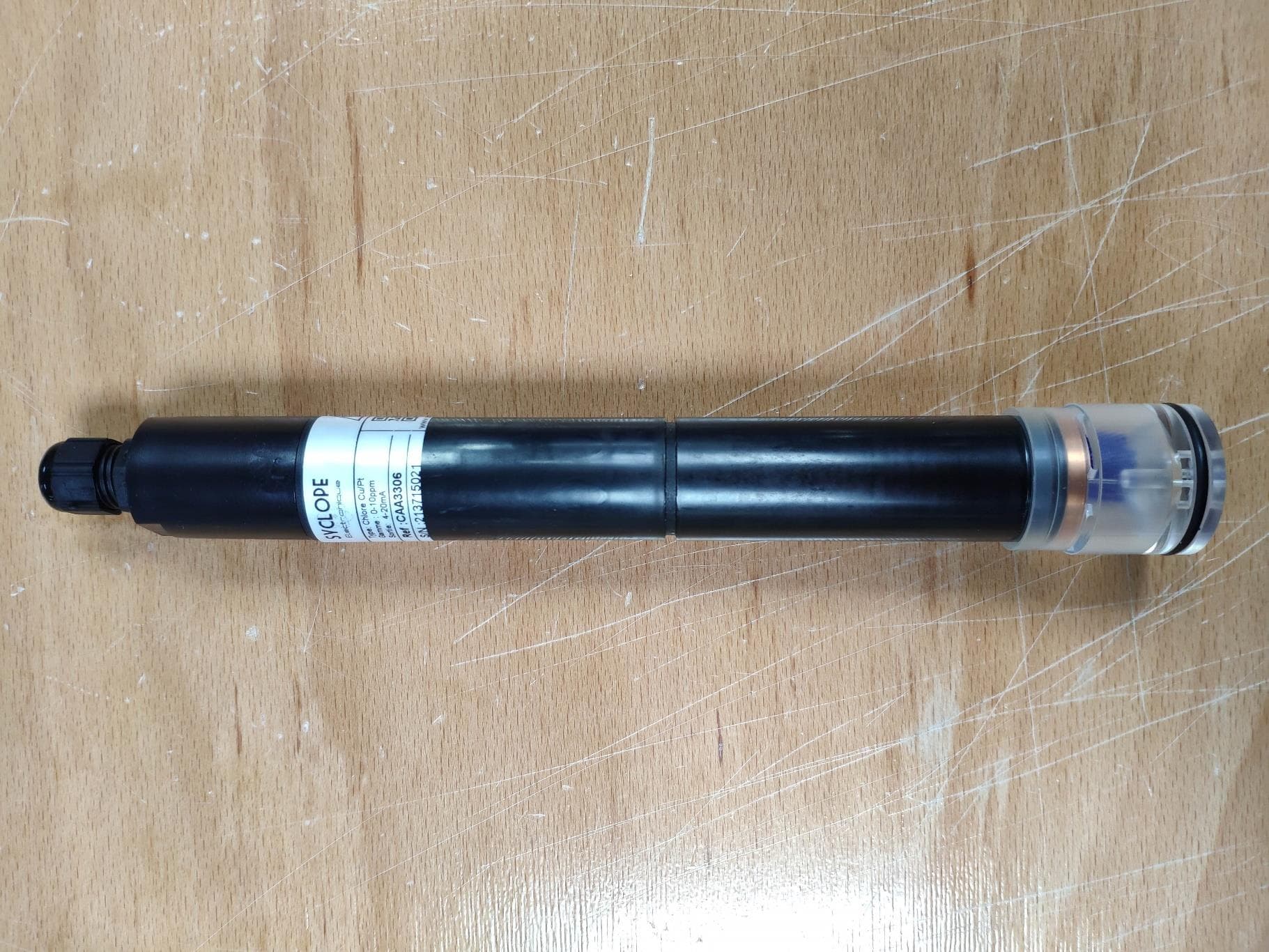
Click to zoom
Application Details
- Equipment Class
- JAB - Part 15 Class B Digital Device
- Date of Grant
- Apr 06, 2022
- Application Purpose
- Original Equipment
- Date of Application
- Apr 06, 2022
- Equipment Note
- electrode free chlorine sensor
- Company
- Syclope Electronique
- Country
- France
Documents & Files
Document Text
Text extracted from the exhibit documents filed with the FCC. Open a document above to read the original.
Users Manual
2 electrode free chlorine sensor Type CAA320X Co/Gold version Type CAA330X Co/Platinum version Installations and commissioning instructions Reference: DOC0514 Rev :1.0 General information Page 2/24 Installation and commissioning instructions General information: SYCLOPE Electronique 2020 ® Manual of 06/04/2020 Rev: 1.0 Free chlorine sensor Installation and commissioning instructions (Ref: DOC514) Editor: SYCLOPE Electronique S.A.S. Z.I. Aéropole Pyrénées Rue du Bruscos 64 230 SAUVAGNON - France – Tel: +33 559 337 036 Fax: +33 559 337 037 Email: [email protected] Internet: http://www.syclope.fr © 2020 by SYCLOPE Electronique S.A.S. Subject to modifications Content Page 3/24 Installation and commissioning instructions Content I. Generality .................................................................................................................. 4 1) Use of the document ......................................................................................................... 4 2) Symbols and signs ............................................................................................................. 4 3) Storage and transport ........................................................................................................ 5 4) Packaging ......................................................................................................................... 5 5) Warranty .......................................................................................................................... 5 6) FCC conformity.................................................................................................................. 6 II. Safety and environmental instructions ..................................................................... 7 1) Use of the equipment ........................................................................................................ 7 2) User obligations ................................................................................................................ 7 3) Risk prevention ................................................................................................................. 7 4) Probe rating plate identification Cu/Au CAA320X ................................................................. 8 5) Probe rating plate identification Cu/Pt CAA330X .................................................................. 9 6) FCC conformity................................................................................................................ 10 7) Disposal and conformity ................................................................................................... 11 III. Technical specifications .......................................................................................... 12 1) Technical specifications .................................................................................................... 12 2) Parameters and Measurement scale ................................................................................. 12 IV. Installation conditions ............................................................................................ 13 V. Mechanical and hydraulic installation ..................................................................... 13 1) Probe overview ............................................................................................................... 13 2) Installation in the probe housing ...................................................................................... 14 VI. Electrical connections ............................................................................................. 16 1) Electrical connections ...................................................................................................... 16 2) Analog power and output operational connections ............................................................. 16 VII. Calibration ............................................................................................................... 17 1) Calibration of the sensor slope ......................................................................................... 17 2) Zero-point calibration (if required) .................................................................................... 17 3) Use of the gain multiplier switch ....................................................................................... 17 VIII. Maintenance ............................................................................................................ 18 1) Disassembly the probe of the measuring chamber ............................................................. 18 2) Change of glass beads ..................................................................................................... 18 3) Change of the copper counter-electrode ........................................................................... 19 IX. Maintenance kit ....................................................................................................... 20 X. Maintenance ............................................................................................................ 21 Generality Page 4/24 Installation and commissioning instructions I. Generality 1) Use of the document Please read carefully the entire document before starting the installation and the commissioning of the controller device, in order to ensure the safety of swimmers, users and equipment’s. The information provided in this document must be strictly observed. SYCLOPE Electronique S.A.S. declines all responsibility in cases where failure to comply with the instructions of this documents. The following symbols and pictograms will be used to facilitate reading and understanding of these instructions. ● Information ► Action to do Element of a list or enumeration 2) Symbols and signs Identification of a continuous volage or current The manual must be consulted before using the product. Risk of …
Text truncated - open the document above for the full version.
Cover Letter(s)
CONFIDENTIALITY REQUEST To: Federal Communications Commission Authorization and Evaluation Division 7435 Oakland Mills Road Columbia, MD 21046-1609 Cc: Timco Engineering, Inc. 849 NW State Road 45 Newberry, Florida 32669 - United States April 4, 2022 Subject: Confidentiality request FCC ID: 2AS3B-PROBE-CUPT Syclope Electronique requests, pursuant to 47CFR 0.457 and 0.459, post grant confidentiality for portions of the material contained in this application. The following document regarding this submission for FCC ID: 2AS3B-PROBE-CUPT shall be kept confidential: LONG-TERM CONFIDENTIALITY: 1. Block Diagram description of the equipment (file: Block Diagram - 2AS3B-PROBE-CUPT.pdf) 2. Operational description of the equipment (file:Operational Description -2AS3B-PROBE-CUPT.pdf) 3. Schematic Diagram of the equipment (file: Schematic -2AS3B-PROBE-CUPT.pdf) The above materials contain trade secrets and proprietary information not customarily released to the public. The public disclosure of these materials may be harmful to the applicant and provide unjustified benefits to its competitors. Permanent Confidentiality: The applicant requests the exhibits listed above as permanently confidential be permanently withheld from public review due to materials that contain trade secrets and proprietary information not customarily released to the public. The applicant understands that disclosure of this application and all accompanying documentation will not be made before the date of the Grant for this application. Sincerely, Responsible party: Thomas Koetzing Title: President Signature:
Cover Letter(s)
COVER LETTER Syclope Electronique – CAA3205 / CAA3206 / CAA3305 / CAA3306 FCC ID: 2AS3B-PROBE-CUPT March 29, 2022 This report concerns: File : Original Grant SubPart: SubPart 15B Equipment type : electrode free chlorine sensor Request issue of grant : __ Immediately upon completion of review ___ Defer grant per 47 CFR 0.457(d)(1)(ii) until ____ date _____. Company Name agrees to notify the Commission by _____date_____ of the intended date of announcement of the product so that the grant can be issued on that date. Confidentiality of grant : __ Applicant requests the existence of this grant to be kept confidential until ____date____. The announcement of this product before this date via freedom of information would be detrimental to Company Name, and therefore must be considered a business secret. Public announcement of this product will not be made prior to this date. (Max. 60 days after grant issued). Limits used : (check one) CISPR 22: ______ Part15: ______ Measurement procedure used is ANSI C63.4-2014 / C63.10-2013 unless another is specified. Other test procedure : ____________________________________________________ Application for verification Applicant for this device Prepared by : MOURZAGH Majid LCIE Sud-Est ZI Centr’Alp – 170, rue de Chatagnon 38430 MOIRANS - France Ph. : 33 4 76 07 36 36 Fax : 33 4 76 55 90 88 e-mail : [email protected] FRN : 0005-0971-18 Thomas Koetzing Syclope Electronique Rue du Bruscos 64230 - Sauvagnon - France Ph. : +49 6221 842 503 e-mail: [email protected] FRN : 0028402253 Signature : Signature : *Not to be filed with Equipment Authorization Branch of FCC unless requested Report format prepared by the Information Technology Industry Council (ITI) ESC-5 and reviewed by FCC staff in 1994
Cover Letter(s)
Date: March 29, 2022 Innovation, Science and Economic Development Canada Certification & Engineering Bureau 3701 Carling Ave., Building 94 Ottawa, Ontario K2H 8S2 SUBJECT: End Product Model Difference Attestation FCC ID: 2AS3B-PROBE-CUPT Brand/Trade Name: Syclope Electronique Model Number: CAA3205 / CAA3206 / CAA3305 / CAA3306 We, Syclope Electronique, hereby declare that our end product, Syclope Electronique, includes CAA3205 / CAA3206 / CAA3305 / CAA3306 as listed above. The above listed models are electrically and mechanically identical. The intention of these models is only for [the second digit indicates the natue of the electrode (2: gold; 3: platinum) and the last digit indicates the measurement range (5: 0-2ppm; 6: 0- 10ppm),change made thanks to a switch (gain multiplier)] purpose. Should you have any question, feel free to contact me directly. Sincerely yours, ----------------------------------- Thomas Koetzing +49 6221 842 503 [email protected]
Cover Letter(s)
Letter of Agency March 29, 2022 To: Federal Communications Commission 7435 Oakland Mills Road Columbia, MD 21046-1609 Timco Engineering, Inc. 849 NW State Road 45 Newberry, Florida 32669 - United States We, the undersigned Syclope Electronique hereby authorizes MOURZAGH Majid, LCIE SUD EST, to act on our behalf in all matters relating to all processes required for FCC certification of our devices. Any and all acts carried out by the above agent on our behalf shall have the same effects as acts of our own. This authorization is valid until: July 31, 2022 If you have any questions regarding this authorization, let us know please. Sincerely, Thomas Koetzing Signature
External Photos
LCIE SUD EST Laboratoire de Moirans Z.I. Centr’Alp 170, Rue de Chatagnon 38430 MOIRANS – France Page 1/3 EXTERNAL PHOTOS OF EQUIPMENT FCCID: 2AS3B-PROBE-CUPT LCIE SUD EST Laboratoire de Moirans Z.I. Centr’Alp 170, Rue de Chatagnon 38430 MOIRANS – France Page 2/3 LCIE SUD EST Laboratoire de Moirans Z.I. Centr’Alp 170, Rue de Chatagnon 38430 MOIRANS – France Page 3/3
ID Label/Location Info
LCIE SUD EST Laboratoire de Moirans Z.I. Centr’Alp 170, Rue de Chatagnon 38430 MOIRANS - FRANCE Page 1/2 PRODUCT LABELING FCCID: 2AS3B-PROBE-CUPT LCIE SUD EST Laboratoire de Moirans Z.I. Centr’Alp 170, Rue de Chatagnon 38430 MOIRANS - FRANCE Page 2/2
Internal Photos
LCIE SUD EST Laboratoire de Moirans Z.I. Centr’Alp 170, Rue de Chatagnon 38430 MOIRANS – France Page 1/2 INTERNAL PHOTOS OF EQUIPMENT FCCID: 2AS3B-PROBE-CUPT LCIE SUD EST Laboratoire de Moirans Z.I. Centr’Alp 170, Rue de Chatagnon 38430 MOIRANS – France Page 2/2
Test Report
This document shall not be reproduced, except in full, without the written approval of the LCIE. This document contains results related only to the items tested. It does not imply the conformity of the whole production to the items tested. Unless otherwise specified or rule defined by the test method, the decision of conformity doesn’t take into account the uncertainty of measures. This document doesn’t anticipate any certification decision. TEST REPORT N°: 171326-762045-A (FILE#1045110) Version : 03 Subject Electromagnetic compatibility tests according to the standards: FCC CFR 47 Part 15, Subpart B. ANSI C63.4 (2014) ICES-003 (2020) Issued to SYCLOPE ELECTRONIQUE Rue du Bruscos 64230 - SAUVAGNON France Apparatus under test Product Electrode free chlorine sensor Trade mark SYCLOPE Manufacturer SYCLOPE Family range Type CAA320X Co/Gold version and Type CAA330X Co/Platinum version Model under test CAA3206 Serial number 204500534 FCCID 2AS3B-PROBE-CUPT Conclusion See Test Program chapter Test date February 8, 2021 Test location MOIRANS FCC Test site FR0008 - 197516 IC Test site FR0008 – 6500A Sample receipt date February 5, 2021 Composition of document 15 pages Document issued on April 4, 2022 Written by : Majid MOURZAGH Tests operator TEST REPORT N° 171326-762045-A (FILE#1045110) Version : 03 Page 2/15 PUBLICATION HISTORY Version Date Author Modification 01 February 19, 2021 Majid MOURZAGH Creation of the document 02 March 28, 2022 Majid MOURZAGH Adding FCC ID on page 1 03 April 4, 2022 Majid MOURZAGH Add pictures on test setup RADIATED EMISSION Each new edition of this test report replaces and cancels the previous edition. The control of the old editions of report is under responsibility of client. TEST REPORT N° 171326-762045-A (FILE#1045110) Version : 03 Page 3/15 SUMMARY 1. TEST PROGRAM ............................................................................................................................. 4 2. EQUIPMENT UNDER TEST: CONFIGURATION (DECLARED BY PROVIDER) .............................. 5 3. MEASUREMENT OF RADIATED EMISSION (30MHZ-1GHZ) ......................................................... 8 4. UNCERTAINTIES CHART .............................................................................................................. 15 TEST REPORT N° 171326-762045-A (FILE#1045110) Version : 03 Page 4/15 1. TEST PROGRAM 1.1. FCC PART15B / ICES-003 Standard: ✓ FCC Part 15, Subpart B (Digital Devices) ✓ ANSI C63.4 (2014) ✓ ICES-003 (2020) 1.1.1. Requirements for disturbance emissions – Class B EMISSION TEST LIMITS RESULTS (Comments) Limits for conducted disturbance 150kHz-30MHz FCC §15.107 Access: AC power NA Frequency Quasi-peak Average 150-500kHz 66 to 56 dBμV 56 to 46 dBμV 0.5-5MHz 56 dBμV 46 dBμV 5-30MHz 60 dBμV 50 dBμV Radiated emissions 30MHz-1GHz FCC §15.109 Access: Enclosure port of ancillary equipment PASS Frequency Quasi-peak @10m 30MHz-88MHz 40.0 dBμV/m 88MHz-216MHz 43.5 dBμV/m 216MHz-960MHz 46.0 dBμV/m Above 960MHz 54.0 dBμV/m Radiated emissions 1GHz- Highest FrequencyGHz* FCC §15.109 Access: Enclosure port of ancillary equipment NA Frequency Peak @3m Average @3m 1- Highest FrequencyGHz 74.0 dBμV/m 54.0 dBμV/m NA: Not Applicable / NP: Not Performed, not requested by the customer (It cannot be taken into account for the declaration of conformity) D : Divergence, the last version is used to make it possible to test the product with the standard which describes the current state of the art and thus to answer as well as possible his environment of final use. *§15.33: The highest internal source of a testing device is defined like more the highest frequency generated or used in the testing device or on which the testing device works or agrees. - If the highest frequency of the internal sources of the testing device is lower than 108 MHz, measurement must be only performed until 1GHz. - If the highest frequency of the internal sources of the testing device ranges between 108 MHz and 500 MHz, measurement must be only performed until 2GHz. - If the highest frequency of the internal sources of the testing device ranges between 500 MHz and 1 GHz, measurement must be only performed until 5GHz. If the highest frequency of the internal sources of the testing device is above 1 GHz, measurement must be only performed until 5 times the highest frequency or 40 GHz, while taking smallest of both. Special condition for intentional radiator: TEST REPORT N° 171326-762045-A (FILE#1045110) Version : 03 Page 5/15 2. EQUIPMENT UNDER TEST: CONFIGURATION (DECLARED BY PROVIDER) 2.1. HARDWARE IDENTIFICATION (EUT AND AUXILIARIES): Equipment under test (EUT): CAA3206 Serial Number: 204500534 Equipment Under Test Power supply: During all the tests, EUT is supplied by V nom : 12VDC For measurement with different voltage, it will be presented in test method. Name Type Rating Reference / Sn Comments Supply AC DC Battery 10-25VDC 25mA / / Inputs/outputs - Cable: Access Type Length used (m) Declared <3m Shielded Under test Comments Supply 2 wires 9 Supply1 and Access1 are the same cable Access1 4-20mA output 9 Supply1 and Access1 are the same cable TEST REPORT N° 171326-762045-A (FILE#1045110) Version : 03 Page 6/15 Auxiliary equipment used during test: Type Reference Sn Comments Multimeter FLUKE 289 / / DC power supply METRIX AX503 / / 2.2. EUT CONFIGURATION – RUNNING MODE Hardware information Highest internal frequency (PLL, Quartz, Clock, Microprocessor...): F Highest : NC <108MHz MHz Firmware (if applicable): V. : N/A Software (if applicable): V. : N/A Configuration n°1: Setup: Resistor simulates chlorinated water and allows mesure value on 4-20mA output. Control: Mesure of 4-20mA ouput by amperemeter. 2.3. EQUIPMENT MODIFICATIONS None Modification: 2.4. SPECIAL ACCESSORIES None TEST REPORT N° 171326-762045-A (FILE#1045110) Version : 03 Page 7/15 2.5. FIELD STRENGTH CALCULATION The field strength is calculated by adding the Antenna Factor and Cable Factor, and s…
Text truncated - open the document above for the full version.
Test Setup Photos
LCIE SUD EST Laboratoire de Moirans Z.I. Centr’Alp 170, Rue de Chatagnon 38430 MOIRANS - FRANCE Page 1/2 CONDUCTED AND RADIATED MEASUREMENT PHOTO FCCID: 2AS3B-PROBE-CUPT 1.1 Radiated emissions Test photo setup on anechoic chamber LCIE SUD EST Laboratoire de Moirans Z.I. Centr’Alp 170, Rue de Chatagnon 38430 MOIRANS - FRANCE Page 2/2 Test photo setup on OATS
Contact Information
Applicant
Thomas Koetzing(President)
Test Firm
LCIE Etablissement Sud-EstAnthony Merlin
Technical Specifications
| # | Rule Parts | Frequency Range | Power Output |
|---|---|---|---|
| 1 | 15B | - | - |