2AS3V-D107-1Azuga Safetycam
Azuga Inc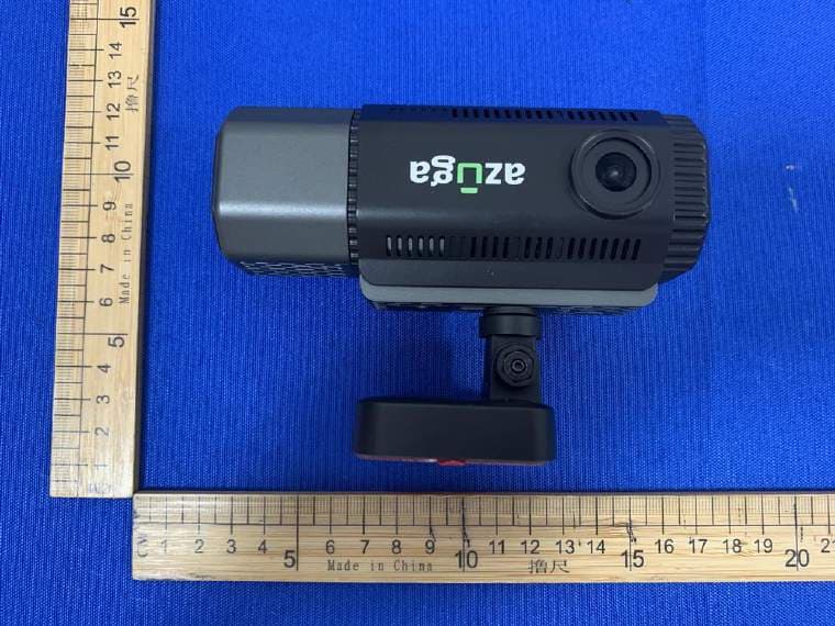
Click to zoom
Application Details
- Equipment Class
- NII - Unlicensed National Information Infrastructure TX
- Date of Grant
- Sep 13, 2023
- Application Purpose
- Original Equipment
- Date of Application
- Sep 13, 2023
- Equipment Note
- Azuga Safetycam
- Frequency Range
- 5180.00000000 - 5240.00000000
- Company
- Azuga Inc
- Country
- United States
Documents & Files
Document Text
Text extracted from the exhibit documents filed with the FCC. Open a document above to read the original.
Users Manual
Gen2Dashcam - UserGuide ©2023Azuga,Inc.Allrightsreserved. Introduction: AdvancedDashCamerawithduallens(frontandrear)canrecordbothroadanddriverfacingwithADAS andAIfeaturescanbeaddedwithsoftware,InbuilthardwarechipsetprovisionedforADAS/DMS featuresinthedashcamera Acardashcamismountedonthefrontwindscreen,thatisbehindtheinteriorrearviewmirror. Thispositiongivesaclearvisionforthecameratocapturewhat’sgoingonahead.Acar recordingcameraisconnectedinsuchawaythatitautomaticallyswitcheson,andstarts recordingassoonasyouswitchonthecar’signition.So,youwillnevermissoutarecording whiledrivingyourcarwithadashcam. TherecordedvideofilesarestoredinanSDcard,anddependingonthesizeofthecard,you needtodeletetheoldfiles.Dashboardcamerasevencomewithinternalstorage.Butifthe dashcamhasaloop-recordingfeature,itautomaticallydeletestheoldfilesandmakesstorage spaceforthenewfiles.So,thisdashcamisefficientinitsoperation,andtherearenochances ofyoumissingoutonanyrecordings. Azugaplansonprovidingadashcamv2solutiontofleetsaspartofitssafetypackage.The dashcamisdesignedtobeanin-vehicleincidentcameratoprovidevideoevidenceofrisky events.ThedefinitionofriskyeventsisderivedfromAzuga’splug‘n’playdevicethatinterfaces withthevehicle’sdiagnosticport. What’sinthebox? BeforeyougetstartedwiththeGen2Dashcam,checkforthefollowingitemsinthebox: Dashcam-1pcSuctionCupMount-1pcScrewdriver-1pc ©2023Azuga,Inc.Allrightsreserved.1 3MTapeHolder-1pcMirrorMountHolder-1pcUserManual OBDPowerCable forSafetycam-1pcSDCard-1pcPryTool TechnicalSpecificationsofGen2Dashcam: PhysicalCharacteristics Camera Cabincameraangle:130° Frontcameraangle:145° ElectricalCharacteristics Processor DSPCV25A85SOC SENSORIMX335500MP RGBIRSENSOROV2736 ©2023Azuga,Inc.Allrightsreserved.2 DifferentComponentsofProduct: ● Power/ResetButton ● TF/MicroSDCardslot ● RearCameraPort(MiniUSB) ● SuctionCup/3MTape/MirrorMountSlot ● Lens ● Power/DataPort(MicroUSB) ● Speaker ● Mic ● RearCamera Features: ThereareanumberoffeaturesavailablewiththeGen2Dashcam,including: ● WifiConnection ● CameraResolution: ○ Front:1920x1080MP ○ Rear:1920x1080MP ● DMSfunctionality ● ADASCalibration ● SonysensorFrontcamera ● RGBIRsensorinnercamera ● Upto145-degreewideangleinnercamera ● Upto120-degreewideangleFrontcamera ● Built-inG-sensor ● Comeswith128/64GBSDcard ● Azugacloudservers ©2023Azuga,Inc.Allrightsreserved.3 ● AudioRecording InstallationSteps: FollowthebelowinstructionsformountingyourDashcamtothewindshieldofyourvehicle: FrontCameraInstallation: 1.Slidethecarmountintotheslotontopofthedeviceuntilaclicksoundisheard. 2.ConnecttheDashcamtothecarpoweroutlet. 3.Turnonthecamera,andwhilstlookingatthecamera,findasuitablelocationonyourwindshield tomounttheDashcam. 4.Pressthesuction-cupfirmlyagainstyourwindshield,androtatetheleverclockwise(12o’clock)to secure. 5.Usethehandtoolprovidedtotuckthepowercableintotheheadliner. 6.Inmostcases,thepowercablecanbetuckedbehindtherubbertrimalongtheA-pillarand doorframe.Usethehandtoolprovidedorgentlytugontherubbertrimtoremoveittomakeroom forthepowercable.Therubbertrimcanbereplacedafterusingthehandtool.Inrarecases,it maybenecessarytoremovetheA-pillarcover. 7.Tracethecabledownthesideofthedoorframetothefloorofthevehicle.Thenliftthecarpetin thepassengersidefoot-wellandtracethecablebeneathit. 8.Alternatively,routethepowercabledownthedoorframeandtuckitbehind/belowtheglovebox. Usecableclipsifrequired. 9.Bringthecableoutofthecenterconsoletothelighter/auxiliarypowersocket. ©2023Azuga,Inc.Allrightsreserved.4 DevicePositionAdjustment 1.Loosenthenutstoswivelthedevicevertically.Clickintoplaceandsecurebytighteningthenuts. 2.Swivelthedevicehorizontallyforaclearview. ConnectingtoPower 1.UseonlythesuppliedcaradaptertopowertheDashcamandchargethebuilt-inbattery. 2.PlugoneendoftheUSBchargingcableintotheMicroUSBport(7)ontheDashcam. 3. Plugtheotherendofthecableintoyourcar’sUSBcharger,andinsertthechargerintoyour vehicle’scigarettelightersocket.AutomaticPowerOncethevehicle’sengineisswitchedon,the Dashcamautomaticallypowerson. ButtonFunctionality Function/ActionButtonEngagementDuration Manualrecordvideoandsendto OBD-II SinglepressandreleaseForatleast0.5second Softreset/restartDashcamAcontinuouspressfor8 seconds 8seconds HardresetDashcamtofactory settings Acontinuouspressfor32 seconds 32seconds VideoSettings NameDescriptionValue PredurationofeventTimeperiodbeforetheevent occurred ● Default:8sec ● Range:1secto30sec DashcamEventVideoLengthDurationforwhichmanually triggeredeventwillbecaptured ● Default:12sec ● Range:1secto30sec ©2023Azuga,Inc.Allrightsreserved.5 FCC Statement This device complies with Part 15 of the FCC Rules. Operation is subject to the following two conditions: (1)This device may not cause harmful interference. (2)This device must accept any interference received, including interference that may cause undesired operation. 2. Changes or modifications not expressly approved by the party responsible for compliance could void the user’s authority to operate the equipment. Note:This equipment has been tested and found to comply with the limits for a class B digital device,pursuant to Part 15 of the FCC Rules. These limits are designed to provide reasonable protection against harmful interference in a residential installation. This equipment generates uses and can radiate radio frequence energy and,if not installed and used in accordance with the instructions,may cause harmful interference to radio communications.However,there is no guarantee that interference will not occur in a particular installation.if this equipmemt does cause harmful interference to radio or television reception,which can be determined by turning the equipment off and on,the user is encouraged to try to correct the interference by one or more of the following measures: • Reorient or relocate the receiving antenna. • Increase the separation between the equipment and receiver. • Connect the equipment into an autlet on a circuit different from that to which the receiver is connected. • Consult the dealer or an experienced radio/TV t…
Text truncated - open the document above for the full version.
Attestation Statements
Azuga Inc 2023-09-09 Eurofins Electrical and Electronic Testing NA, Inc. 914 West Patapsco Avenue Baltimore, MD 21230 RE: Attestation Statements Part 2.911(d)(5)(i) request for (FCC ID: 2AS3V-D107-1 ) [Azuga Inc ] (“the applicant”) certifies that the equipment for which authorization is sought is not “covered” equipment prohibited from receiving an equipment authorization pursuant to section 2.903 of the FCC rules. Sincerely, Aditya Rana IOT Product Manager Azuga Inc 42840 Christy St. #205, Fremont, CA 94508 Azuga Inc 2023-09-09 Eurofins Electrical and Electronic Testing NA, Inc. 914 West Patapsco Avenue Baltimore, MD 21230 RE: Attestation Statements Part 2.911(d)(5)(ii) request for(FCC ID: 2AS3V-D107-1 ) [Azuga Inc ] (“the applicant”) certifies that, as of the date of the filing of the application, the applicant is not identified on the Covered List as an entity producing “covered” equipment. Sincerely, Aditya Rana IOT Product Manager Azuga Inc 42840 Christy St. #205, Fremont, CA 94508
Attestation Statements
Attestation Statements (2023-8-21) TO: Federal Communications Commission Authorisation and Evaluation Division 7435 Oakland Mills Road Columbia, MD 21046, USA RE: Attestation Statements Part 2.911(d)(7) request for (FCC ID: 2AS3V-D107-1) Azuga Inc., the undersigned, hereby authorise Azuga Inc. to act as our designated U.S. agent for the service of process, Azuga Inc. accepts to maintain an agent for no less than one year after the grantee has terminated all marketing and importation or the conclusion of any Commission-related proceeding involving the equipment. Azuga Inc. accepts the responsibility to act as a designated U.S. agent for the service of process. Applicant Information: Company name: Azuga Inc Contact Name: Aditya Rana Address:42840 Christy St. #205, Fremont, CA 94508 Telephone No: 4084048552 Email: [email protected] Signature U.S. Agent Information: Company Name: Azuga Inc Address: 42840 Christy St. #205, Fremont, CA 94508 FRN: 0028409316 Contact Name: Aditya Rana Telephone No: 4084048552 Email: [email protected] Signature
Cover Letter(s)
Azuga Inc 2023-09-09 Eurofins Electrical and Electronic Testing NA, Inc. 914 West Patapsco Avenue Baltimore, MD 21230 RE: CONFIDENTIALITY REQUEST FOR (EUT Name: Azuga Safetycam /Model: Gen-2 D107 /FCC ID: 2AS3V-D107-1) To Whom It May Concern: This letter serves as an official request for confidentiality under sections 0.457 and 0.459 of CFR 47. We have requested that the (Block Diagram ,Operational Description,Schematics, FCC SW SECURITY DESCRIPTION ) required to be submitted with this application be permanently withheld from public review. The above materials contain trade secrets and proprietary information not customarily released to the public. The public disclosure of these materials may be harmful to the applicant and provide unjustified benefits to its competitors. Please contact me if there is any information you may need. Sincerely, Aditya Rana IOT Product Manager Azuga Inc 42840 Christy St. #205, Fremont, CA 94508
Cover Letter(s)
Azuga Inc 2023-09-09 Eurofins Electrical and Electronic Testing NA, Inc. 914 West Patapsco Avenue Baltimore, MD 21230 RE: LETTER OF AGENT AUTHORIZATION To Whom It May Concern: We, the undersigned, hereby authorize Guangdong Global Testing Technology Co., Ltd. to act on our behalf in all matters relating to application for equipment authorization, including the signing of all documents relating to these matters. We also hereby certify that no party to the application authorized hereunder is subject to the denial of benefits, including FCC benefits, pursuant to Section 5301 of the Anti-Drug Abuse Act of 1988, 21 U.S.C.853(a). This agreement expires one year from the current date. Sincerely, Aditya Rana IOT Product Manager Azuga Inc 42840 Christy St. #205, Fremont, CA 94508
External Photos
External
Internal Photos
Internal
RF Exposure Info
RF EXPOSURE EVALUATION According to FCC 1.1310: The criteria listed in the following table shall be used to evaluate the environment impact of human exposure to radio frequency(RF) Radiation as specified in §1.1307(b) FCC ID: 2AS3V-D107-1 EUT Specification EUT Azuga Safetycam Model Number Gen-2 D107 Rating DC 5V, 2A Frequency band (Operating) BT: 2.402GHz ~ 2.480GHz WLAN: 2.412GHz ~ 2.462GHz WLAN: 5.18GHz ~ 5.32GHz WLAN: 5.50GHz ~ 5.70GHz WLAN: 5.745GHz ~ 5.825GHz Device category Portable (<20cm separation) Mobile (>20cm separation) Exposure classification Occupational/Controlled exposure (S = 5mW/cm2) General Population/Uncontrolled exposure (S=1mW/cm2) Antenna diversity Single antenna Multiple antennas Tx diversity Rx diversity Tx/Rx diversity Max. output power(peak power) IEEE 802.11b: 12.19 dBm IEEE 802.11g: 10.49 dBm IEEE 802.11n-HT20: 10.13 dBm IEEE 802.11n-HT40: 9.45 dBm 5180 MHz to 5240 MHz: 10.89 dBm Antenna gain (Max) 2.4GHz WIFI: 2.17dBi 5.8G WIFI: 1.74dBi Evaluation applied MPE Evaluation SAR Evaluation Limits for Maximum Permissible Exposure(MPE) Frequency Range(MHz) Electric Field Strength(V/m) Magnetic Field Strength(A/m) Power Density(mW/cm 2 ) Average Time (A) Limits for Occupational/Control Exposures 300-1500-- -- F/300 6 1500-100000 -- -- 5 6 (B) Limits for General Population/Uncontrol Exposures 300-1500 -- -- F/1500 6 1500-100000 -- -- 1 30 Friis transmission formula: Pd=(Pout*G)\(4*pi*R2) Where Pd= Power density in mW/cm 2 , Pout=output power to antenna in Mw G= gain of antenna in linear scale, Pi=3.1416 R= distance between observation point and center of the radiator in cm=20cm Pd the limit of MPE, 1mW/cm2. If we know the maximum gain of the antenna and total power input to the antenna, through the calculation, we will know the distance where the MPE limit is reached. Measurement Result 2.4GHz WIFI: Operation Mode Channel Number Channel Frequency (MHz) Measurement Level (dBm) Limit (dBm) Verdict 802.11b 1 2412 12.19 30 PASS 6 2437 11.67 30 PASS 11 2462 11.21 30 PASS 802.11g 1 2412 10.49 30 PASS 6 2437 9.89 30 PASS 11 2462 9.23 30 PASS 802.11n (HT20) 1 2412 10.13 30 PASS 6 2437 9.68 30 PASS 11 2462 9.03 30 PASS 802.11n (HT40) 3 2422 9.45 30 PASS 6 2437 9.25 30 PASS 9 2452 9 30 PASS Operating Mode Test Channel Tune up tolerance (dBm) Max tune up conducted power(dBm) Output Peak power (mW) Ant. Gain (dBi) Ant. Gain (numeric) Power density at 20cm (mW/ cm2) Power density Limits (mW/ cm2) 802.11b 1 12±1 13 19.953 2.17 1.648 0.006542 1 6 12±1 13 19.953 2.17 1.648 0.006542 1 11 11±1 12 15.849 2.17 1.648 0.005197 1 802.11g 1 10±1 11 12.589 2.17 1.648 0.004128 1 6 10±1 11 12.589 2.17 1.648 0.004128 1 11 9±1 10 10.000 2.17 1.648 0.003279 1 802.11n (HT20) 1 10±1 11 12.589 2.17 1.648 0.004128 1 6 10±1 11 12.589 2.17 1.648 0.004128 1 11 9±1 10 10.000 2.17 1.648 0.003279 1 802.11n (HT40) 3 9±1 10 10.000 2.17 1.648 0.003279 1 6 9±1 10 10.000 2.17 1.648 0.003279 1 9 9±1 10 10.000 2.17 1.648 0.003279 1 5.8GHz WIFI: UNII-1: Operation Mode Channel Number Channel Frequency (MHz) Measurement Level (dBm) Limit (dBm) Verdict Ant1 802.11a 36 5180 10.89 24 PASS 40 5200 10.53 24 PASS 48 5240 10.45 24 PASS 11n HT20 36 5180 10.42 24 PASS 40 5200 10.02 24 PASS 48 5240 10 24 PASS 11n HT40 38 5190 10.47 24 PASS 46 5230 10.39 24 PASS 11ac VHT20 36 5180 9.33 24 PASS 40 5200 9.15 24 PASS 48 5240 9.14 24 PASS 11ac VHT40 38 5190 8.83 24 PASS 46 5230 8.77 24 PASS 11ac VHT80 42 5210 6.64 24 PASS Operating Mode Test Channel Tune up tolerance (dBm) Max tune up conducted power(dBm) Output Peak power (mW) Ant. Gain (dBi) Ant. Gain (numeric) Power density at 20cm (mW/ cm2) Power density Limits (mW/cm2) 802.11a 36 11±1 12 15.849 1.74 1.493 0.004707 1 40 11±1 12 15.849 1.74 1.493 0.004707 1 48 10±1 11 12.589 1.74 1.493 0.003739 1 802.11n HT20 36 10±1 11 12.589 1.74 1.493 0.003739 1 40 10±1 11 12.589 1.74 1.493 0.003739 1 48 10±1 11 12.589 1.74 1.493 0.003739 1 802.11n HT40 38 10±1 11 12.589 1.74 1.493 0.003739 1 46 10±1 11 12.589 1.74 1.493 0.003739 1 802.11ac VHT20 36 9±1 10 10.000 1.74 1.493 0.002970 1 40 9±1 10 10.000 1.74 1.493 0.002970 1 48 9±1 10 10.000 1.74 1.493 0.002970 1 802.11ac VHT40 38 9±1 10 10.000 1.74 1.493 0.002970 1 46 9±1 10 10.000 1.74 1.493 0.002970 1 802.11ac VHT80 42 7±1 8 6.310 1.74 1.493 0.001874 1 The Product unsupported at the same time to Transmitting. According to KDB 447498, and no simultaneous SAR measurement is required. Signature: Shawn Wen Date: 2023-09-09
Test Report
Page 9 of 919 SPECIFICATION FOR APPROVAL (Product Recognition) Product Name: WIFI Antenna Product model (original model): UB01NF2D1112A Customer's Material Name: _ WIFI Antenna _ UB01NF2D1112A Customer's "specification model": WIFI antenna UB01NF2D1112A frequency: 2.4/5.8 GHz built-in FPC size: 17.4*16.6 gold finger gold plated ROHS- Customer's "Material Code": Resume of changes: Seria l numb er Content before change Content after change Date of change Versio n Page number Responsible person 0 First edition First edition 2023-2-28 A0 10 Eddy Name of supplier: Dongguan Youbi Electronics Co., Ltd. Supplier's address: Building 79, New Sun Industrial City, No.9 Xinfa Road, Lincun, Tangxia Town, Dongguan City Tel: 0769-81777126 Fax: 0769-81777126 Email: [email protected] (Signed by the Supplier) Responsible person/date Review/Date Approval/Date This acknowledgement includes the following contents: (All are indispensable) First, the cover II. Parameter Specification III. Structural Dimension Drawing IV. BOM V. Packaging drawing VI. Production Process Flow Table VII. Certification Test Status Page 9 of 929 Customer name: Shenzhen Oni Electronics Co., Ltd. Judgment result of buyer (customer):-qualified-unqualified Buyer (customer) acknowledges (please mark back the whole acknowledgement bookmark after confirmation) Development Design Engr/Date SQE Engr/Date Head of Purchasing Department/Date Approval by Development Manager/Date II. Parameter Specification 1. Electrical performance parameters (fill in instructions: the relevant parameters of electrical performance must specify the unit, tolerance and conditions) Seri al num ber Project Parameter specification Test conditions 1 Frequency (MHz) 2400-2500; 5150-5850 Microwave anechoic chamber 2 Gain test ≥ 1 dBi, ≤ 3 dBi Microwave anechoic chamber 3 Efficiency test ≥ 40%, ≤ 70% Microwav e anechoic chamber 4 Center frequency characteristic impedance (Ω) 50 Network analyzer 2. Mechanical performance parameters (fill in instructions: the relevant parameters of mechanical and physical properties must specify the unit, tolerance and conditions) Seri al num ber Project Parameter specification Test conditions 1 FPC length 17.4 ± 0.3 (mm) Measured with a digital caliper, it is OK within 17.4 0.3 (mm) in length and dimension, and NG on the contrary. 2 FPC width 16.6 ± 0.3 (mm) Measured with a digital caliper, the width dimension is OK within 16.6 ± 0.3 (mm), and vice versa is NG. Page 9 of 939 3. Reliability test (fill in instructions: the relevant requirements of reliability test must specify the items, conditions and judgment criteria) Seri al num ber Project Test conditions Standard requirements 1 Salt spray test Test specification: Test temperature: 35 °C, salt solution concentration: 5% (the standard PH value of salt solution after modulation and cooling is between 6.5 and 7.2), average salt solution collection amount: 1.0 ~ 2.0 (ml/hr), test time: 48 hours (terminal)/8H (wire) Experimental method: Inject the prepared brine into the test liquid storage bucket, place the tested object on the test shelf, then close the test cover, and pour the water into the sealed groove until there is no gap. After 48H/8H test, if there is no oxidation on the surface of the product, it will be OK, otherwise it will be NG. After 48H/8H, there is no oxidation on the surface of the product, and the electrical test is OK. 4 Drop test Test conditions: 1. Drop the 6 sides of the carton (as shown in Figure 1) Figure I 2. The product is 80 CM away from the floor steel plate (As shown in Figure 2) Figure II Test method: 1. Fix the packing box to be tested on the product bracket to fix and clamp the test sample, and the clamping force should be appropriate to avoid clamping the tested sample. 2. Adjust the falling height by 80CM. 3. First, turn on the main power switch and turn on the trachea. 4. After the work is finished, disconnect the trachea and power switch and take off the sample. 1. After testing, the packing box shall not be obviously damaged. 2. After the test, the product should be inspected, and the electrical property should not be defective after external inspection. 80CM Page 9 of 949 三、Structural Dimension Drawing (CAD Drawing File) Page 9 of 959 IV. BOM (Bill of Materials) Seri al num ber Component material name Material Specification/model Bran d Name of Supplier Dosage 1 FPC PI 17.4 mm long * 16.6 mm wide \ QG 1PCS 2 PE bag PE Choose suitable specifications \ Pond dragon 1/200 PCS 3 Carton \ Choose suitable specifications \ Jiulongda / 4 5 V. Packaging drawing (filling in instructions: the inserted pictures must be clearly visible) 1. Packaging photos (pictures): 1. Photos or pictures of individual material packaging 2. Photos or pictures placed on a single layer of inner packaging Remarks: Remarks: 3. Photos or pictures of the outer packaging 4. Anti-counterfeiting mark of supplier's material packaging Remarks: Remarks: Supplier Material Coding Rules: General process product coding rules: UB + 01 + N + F + 2D + 1112 + A ① ② ③ ④ ⑤ ⑥ ⑦ 1. UB stands for antenna products; 2. Classification of finished products: 01 is the terminal built-in class; 3. Connection mode code: N is antenna direct connection; 4. F stands for FPCB; 5. Gain description: gain digit + D (DBi); 6. Serial number: 1 to 999999999; 7. Version number: Version A code is A. Page 9 of 969 VII. Certification Test Status (Fill in the instructions: If relevant test certification is done, please tick in brackets and indicate the corresponding certification or report number) () UL certification or report number: () VDE certification or report number: () CE certification or report number: () FCC certification or report number: (√)ROHS certification or report number: A2220006213101E () REACH certification or report number: () EMC certification or report number: () CCC certification or report number: () SRRC certification or report number: () Other certification or report number: () No product certification 1. S P…
Text truncated - open the document above for the full version.
Test Report
TRF No.: 04-E001-1A TRF Originator: GTG TRF Date: 2022-06-29 Web: www.gtggroup.com E-mail: [email protected].: 86-400 755 8988 CFR 47 FCC PART 15 SUBPART E TEST REPORT For Azuga Safetycam MODEL NUMBER: Gen-2 D107 FCC ID: 2AS3V-D107-1 REPORT NUMBER: E04A23030703F00202 ISSUE DATE: Sept. 09, 2023 Prepared for Azuga Inc 42840 Christy St. #205, Fremont, CA, United States, 94508 Prepared by Guangdong Global Testing Technology Co., Ltd. Room 101-105, 203-210, Building 1, No.2, Keji 8 Road, Songshan Lake Park, Dongguan city, Guangdong, People’s Republic of China, 523808 This report shall not be reproduced, except in full, without the written approval of Guangdong Global Testing Technology Co., Ltd. REPORT NO.: E04A23030703F00202 Page 2 of 69 TRF No.: 04-E001-1A Global Testing , Great Quality. Revision History Rev. Issue Date Revisions Revised By V0 Sept. 09, 2023 Initial Issue Win REPORT NO.: E04A23030703F00202 Page 3 of 69 TRF No.: 04-E001-1A Global Testing , Great Quality. Summary of Test Results Test Item Clause Limit/Requirement Result ON TIME AND DUTY CYCLE ANSI C63.10-2013, Clause 12.2 None; for reporting purposes only. Pass 6dB AND 26dB EMISSION BANDWIDTH AND 99% OCCUPIED BANDWIDTH KDB 789033 D02 v02r01 Section C.1 FCC Part 15.407 (a)(2)(5), Pass CONDUCTED OUTPUT POWER KDB 789033 D02 v02r01 Section E.3.a (Method PM) FCC 15.407 (a) Pass POWER SPECTRAL DENSITY KDB 789033 D02 v02r01 Section F FCC 15.407 (a) Pass AC Power Line Conducted Emission ANSI C63.10-2013, Clause 6.2. FCC 15.207 N/A (NOTE 1, 2) Radiated Emissions and Band Edge Measurement KDB 789033 D02 v02r01 Section G.3, G.4, G.5, and G.6 FCC 15.407 (b) FCC 15.209 FCC 15.205 Pass FREQUENCY STABILITY FCC 15.407 (g) Pass Antenna Requirement N/A FCC 47 CFR Part 15.203/ 15.407(a)(1) (2), Pass Note: 1. N/A: In this whole report not applicable. 2. This test is only applicable for devices which can be charged or powered by AC power cable. *The measurement result for the sample received is <Pass> according to <CFR 47 FCC PART 15 SUBPART E > when <Accuracy Method> decision rule is applied. REPORT NO.: E04A23030703F00202 Page 4 of 69 TRF No.: 04-E001-1A Global Testing , Great Quality. CONTENTS 1. ATTESTATION OF TEST RESULTS ..................................................................................... 5 2. TEST METHODOLOGY ......................................................................................................... 6 3. FACILITIES AND ACCREDITATION ..................................................................................... 6 4. CALIBRATION AND UNCERTAINTY ................................................................................... 7 4.1. MEASURING INSTRUMENT CALIBRATION ........................................................... 7 4.2. MEASUREMENT UNCERTAINTY ............................................................................ 7 5. EQUIPMENT UNDER TEST .................................................................................................. 8 5.1. DESCRIPTION OF EUT ........................................................................................... 8 5.1. CHANNEL LIST ........................................................................................................ 9 5.2. MAXIMUM AVERAGE EIRP ..................................................................................... 9 5.3. THE WORSE CASE POWER SETTING PARAMETER ............................................ 9 5.4. DESCRIPTION OF AVAILABLE ANTENNAS ......................................................... 10 5.5. SUPPORT UNITS FOR SYSTEM TEST ................................................................. 11 5.6. SETUP DIAGRAM .................................................................................................. 11 6. MEASURING EQUIPMENT AND SOFTWARE USED......................................................... 12 7. ANTENNA PORT TEST RESULTS ..................................................................................... 14 7.1. ON TIME AND DUTY CYCLE ................................................................................. 14 7.2. 6dB AND 26dB EMISSION BANDWIDTH AND 99% OCCUPIED BANDWIDTH..... 15 7.3. CONDUCTED OUTPUT POWER ........................................................................... 17 7.4. POWER SPECTRAL DENSITY .............................................................................. 19 7.5. FREQUENCY STABILITY ....................................................................................... 21 8. RADIATED TEST RESULTS ............................................................................................... 23 9. ANTENNA REQUIREMENT ................................................................................................ 40 10. TEST DATA ............................................................................................................ 41 APPENDIX: PHOTOGRAPHS OF TEST CONFIGURATION ..................................................... 68 APPENDIX: PHOTOGRAPHS OF THE EUT .............................................................................. 69 REPORT NO.: E04A23030703F00202 Page 5 of 69 TRF No.: 04-E001-1A Global Testing , Great Quality. 1. ATTESTATION OF TEST RESULTS Applicant Information Company Name: Azuga Inc Address: 42840 Christy St. #205, Fremont, CA, United States, 94508 Manufacturer Information Company Name: SHENZHEN AONI ELECTRONIC CO.,LTD Address: No.5 Bldg, Honghui Industrial park, 2nd liuxian Road, Xin'an street, Bao'an District, Shenzhen EUT Information EUT Name: Azuga Safetycam Model: Gen-2 D107 Series Model: N/A Brand: Sample Received Date: March 27, 2023 Sample Status: Normal Sample ID: A23030703 001 Date of Tested: March 27, 2023 to Sept. 09, 2023 APPLICABLE STANDARDS STANDARD TEST RESULTS CFR 47 FCC PART 15 SUBPART E Pass Prepared By: Checked By: Win Huang Alan He Project Engineer Project Engineer Approved By: Shawn Wen Laboratory Supervisor REPORT NO.: E04A23030703F00202 Page 6 of 69 TRF No.: 04-E001-1A Global T…
Text truncated - open the document above for the full version.
Test Setup Photos
Radiated emissions below 1GHz Radiated emissions above 1GHz
Contact Information
Applicant
Aditya Rana(IOT Product Manager)
Test Firm
Guangdong Global Testing Technology Co., Ltd.Shawn Wen
[email protected]86 769 8507 5888
Technical Specifications
| # | Rule Parts | Frequency Range | Power Output |
|---|---|---|---|
| 1 | 15E | 5.18 GHz - 5.24 GHz | 12.30 mW |