2AS5O-CVS-04Mini SoundPods
China Etech Groups Ltd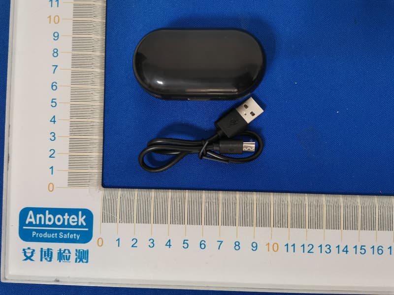
Click to zoom
Application Details
- Equipment Class
- DSS - Part 15 Spread Spectrum Transmitter
- Date of Grant
- Jan 14, 2020
- Application Purpose
- Original Equipment
- Date of Application
- Jan 14, 2020
- Equipment Note
- Mini SoundPods
- Frequency Range
- 2402.00000000 - 2480.00000000
- Company
- China Etech Groups Ltd
- Country
- China
Documents & Files
Document Text
Text extracted from the exhibit documents filed with the FCC. Open a document above to read the original.
Users Manual
True wireless earbuds with charging case Size: 85*55 mm SPECIFICATIONS: DESCRIPTION OF FUNCTIONS Model No. Dimension mm Operating voltage 3.3V-4.2V Battery capacity 30mA/300mA Playing time About 2.5 hours Bluetooth version V5.0 Transmission range 2.40GHz-2.48GHz Trumpet 10mm/32 Euro Titanium Trumpet Sensitivity 98+3dB Communication distance Effective distance 10 meters Oblique ear fitting ear outline 1- Earbuds 2- On/Off button 3- LED indicator 4- Charging case PACKING LIST True wireless earbuds ×1 1. 4. 2. 3. True wireless earbuds 1. Turn on/off Key length press 3 seconds switch, long press 3 seconds shut down when you pick up the headset from the charging cell automatically turn on and back into the charging cell automatically shut down. 2. Bluetooth pairing Turn on the phone and set the Bluetooth function switch to pick up the boot from the charging warehouse. The red and blue lights alternately flash two headphones into the automatic pairing mode. After the pairing is successful, one of the ears is turned off and the main ear blue light is flashing. The Bluetooth interface of the mobile phone shows “XXXXXXX” click on the connection. 3. Left and right ears alone Push the button to boot, search the phone Bluetooth machine to the headphone name “XXXXX” click on the connection, the right ear with the method used alone. 4. Automatic reconnection/single ear silent The phone uses a connected headset. After the headset is paired, the headset will automatically return to the single ear and the two headsets will be silently returned to the charging cell. After removing the Bluetooth list search name of the phone, the tow ears will be reconnected automatically. 5. Headphone charging/charging cell charging Put the headset back into the charging chamber, the red light indicates charging, the blue light is full, and the charging chamber charges the charging wire interface and inserts it. 4 white lights are battery saturation. 6. Ear electricity level When one of the ears has a low battery level, the lower battery tone is issued every 30 seconds. Switch between Chinese and English, double-click the button when Bluetooth is not connected. 1. The headphone pair is successfully operated(playing songs, calling, etc..). 2. Call: Bluetooth connection state, pull the phone short press answer , long press 1.5 seconds the release the refusal, short press hang up under the state of the call, double-click the button to redial the most recent call or unanswered phone number . 3. Song: Play the music interface in the connection state, short press a button to pause, long press the left and right ears next. 4. Headphone power: Headphone voltage is less than 3.3V low power prompt, less than 3.2V automatic shutdown, charging the headphone less than 4.0V , 4.2V full. Model NO.:EBP-B-042 FCC STATEMENT : This device complies with Part 15 of the FCC Rules. Operation is subject to the following two conditions: (1) This device may not cause harmful interference, and (2) This device must accept any interference received, including interference that may cause undesired operation. Warning: Changes or modifications not expressly approved by the party responsible for compliance could void the user's authority to operate the equipment. NOTE: This equipment has been tested and found to comply with the limits for a Class B digital device, pursuant to Part 15 of the FCC Rules. These limits are designed to provide reasonable protection against harmful interference in a residential installation. This equipment generates uses and can radiate radio frequency energy and, if not installed and used in accordance with the instructions, may cause harmful interference to radio communications. However, there is no guarantee that interference will not occur in a particular installation. If this equipment does cause harmful interference to radio or television reception, which can be determined by turning the equipment off and on, the user is encouraged to try to correct the interference by one or more of the following measures: Reorient or relocate the receiving antenna. Increase the separation between the equipment and receiver. Connect the equipment into an outlet on a circuit different from that to which the receiver is connected. Consult the dealer or an experienced radio/TV technician for help. RF warning statement: The device has been evaluated to meet general RF exposure requirement. The device can be used in portable exposure condition without restriction.
External Photos
FCC ID: 2AS5O-CVS-04
ID Label/Location Info
Label Location On EUT LeftRight Label FCC ID: 2AS5O-CVS-04
Internal Photos
FCC ID: 2AS5O-CVS-04 ANT
Operational Description
version01 China Etech Groups Ltd Declaration concerning Antenna Specification It is hereby declared that the product Model No.: EBP-B-042, CVS-04 FCC ID : 2AS5O-CVS-04 fulfills the requirement in FCC test relating to the antenna type. The device specified above confirms to the FCC recommendations for internal antenna type(s) described below: Model No. of antenna: EBP-B-042 Type of antenna:Ceramic Antenna Gain of the antenna: 0 dBi Frequency range:2402-2480MHz The mounting of the antenna is fixed to the radio module and no other antenna should be used. Company name: China Etech Groups Ltd Address: 16/F, Block C, 2nd Phase of Central Avenue, Haihong Industrial Area, Xixiang Road, Baoan District, Shenzhen, China City: Shenzhen ZIP / Postal code: N/A Country:China Place:ChinaDate: 2020-01-13 Signature:
RF Exposure Info
RF EXPOSURE EVALUATION FCC ID: 2AS5O-CVS-04 According to FCC 1.1310: The criteria listed in the following table shall be used to evaluate the environment impact of human exposure to radio frequency(RF) Radiation as specified in §1.1307(b): Routine SAR evaluation refers to that specifically required by §2.1093, using measurements or computer simulation. When routine SAR evaluation is not required, portable transmitters withoutput power greater than the applicable low threshold require SAR evaluation to qualify for TCB approval. Channel (MHz) Maximum output power (dBm) Tune up tolerance (dBm) Max Tune Up Power (dBm) Distance (mm) Calculation results Limit Operating Mode 24022.103 2.103±1 3.10350.6333 BDR+EDR 24412.393 2.393±13.393 5 0.683 3 24802.064 2.064±1 3.06450.6383 24022.719 2.719±1 3.71950.7303 24412.859 2.859±13.859 5 0.760 3 24802.625 2.625±1 3.62550.7263 Test Results:PASS.
Test Report
Report No.: SZAWW191226006-01FCC ID: 2AS5O-CVS-04Page 1 of 63 Code:AB-RF-05-a FCC TEST REPORT Client Name: China Etech Groups Ltd Address: 16/F, Block C, 2nd Phase of Central Avenue,Haihong Industrial Area,XixiangRoad,Baoan,Shenzhen,China Product Name: Mini SoundPods Date: Jan. 13, 2020 Shenzhen Anbotek Compliance Laboratory Limited Report No.: SZAWW191226006-01FCC ID: 2AS5O-CVS-04Page 2 of 63 Code:AB-RF-05-a Contents 1. General Information ............................................................................................................................................... 5 1.1. Client Information ....................................................................................................................................... 5 1.2. Description of Device (EUT) ..................................................................................................................... 5 1.3. Auxiliary Equipment Used During Test ................................................................................................... 6 1.4. Description of Test Modes ........................................................................................................................ 6 1.5. List of channels ........................................................................................................................................... 7 1.6. Description Of Test Setup ......................................................................................................................... 8 1.7. Test Equipment List .................................................................................................................................... 9 1.8. Measurement Uncertainty ....................................................................................................................... 10 1.9. Description of Test Facility ...................................................................................................................... 10 2. Summary of Test Results ................................................................................................................................... 11 3. Conducted Emission Test ................................................................................................................................... 12 3.1. Test Standard and Limit .......................................................................................................................... 12 3.2. Test Setup .................................................................................................................................................. 12 3.3. Test Procedure .......................................................................................................................................... 12 3.4. Test Data .................................................................................................................................................... 12 4. Radiation Spurious Emission and Band Edge ................................................................................................ 15 4.1. Test Standard and Limit .......................................................................................................................... 15 4.2. Test Setup .................................................................................................................................................. 15 4.3. Test Procedure .......................................................................................................................................... 16 4.4. Test Data .................................................................................................................................................... 17 5. Maximum Peak Output Power Test .................................................................................................................. 25 5.1. Test Standard and Limit .......................................................................................................................... 25 5.2. Test Setup .................................................................................................................................................. 25 5.3. Test Procedure .......................................................................................................................................... 25 5.4. Test Data .................................................................................................................................................... 25 6. 20DB Occupy Bandwidth Test ........................................................................................................................... 29 6.1. Test Standard ............................................................................................................................................ 29 6.2. Test Setup .................................................................................................................................................. 29 6.3. Test Procedure .......................................................................................................................................... 29 6.4. Test Data .................................................................................................................................................... 29 7. Carrier Frequency Separation Test ................................................................................................................... 33 7.1. Test Standard and Limit .......................................................................................................................... 33 7.2. Test Setup .................................................................................................................................................. 33 7.3. Test Procedure ..............................................................................................................................…
Text truncated - open the document above for the full version.
Test Setup Photos
FCC ID: 2AS5O-CVS-04 Photo of Conducted Emission Measurement Photo of Radiation Emission Test
Contact Information
Applicant
Paul Huang(Manger)
Test Firm
Shenzhen Anbotek Compliance Laboratory LimitedJeff Zhu
Technical Specifications
| # | Rule Parts | Frequency Range | Power Output |
|---|---|---|---|
| 1 | 15C | 2.40 GHz - 2.48 GHz | 1.94 mW |
Other Applications from China Etech Groups Ltd
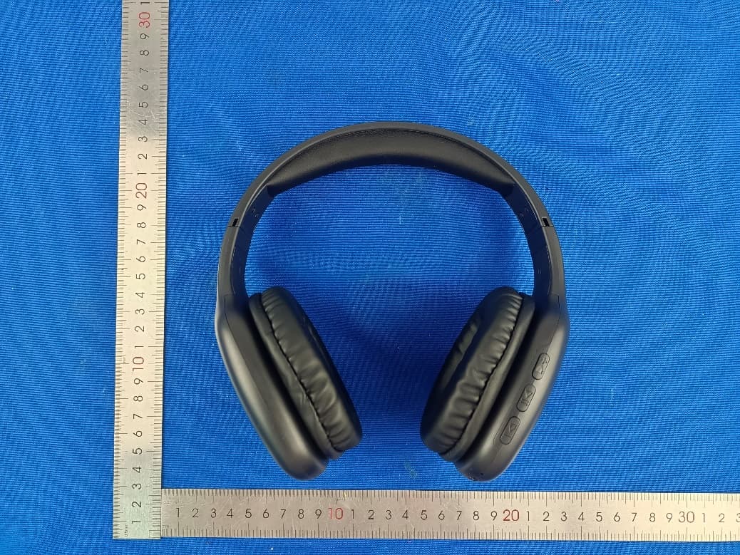
2AS5O-EBP-22055
Mar 19, 2023ART + SOUND BT HEADPHONE
Equipment Class
DSS - Part 15 Spread Spectrum Transmitter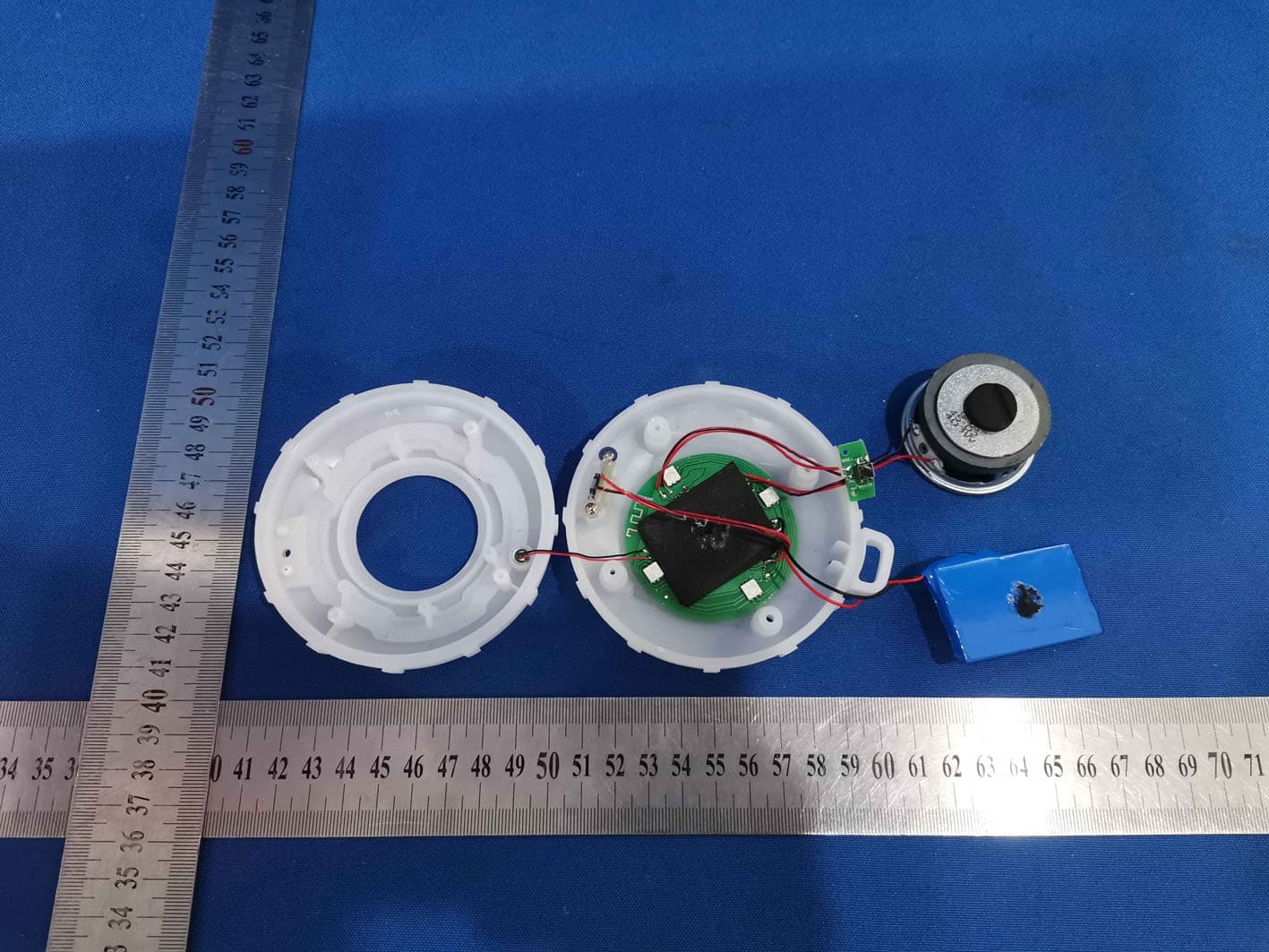
2AS5O-1112B
Nov 03, 2021Fashion Speaker with Colorful Lights
Equipment Class
DSS - Part 15 Spread Spectrum Transmitter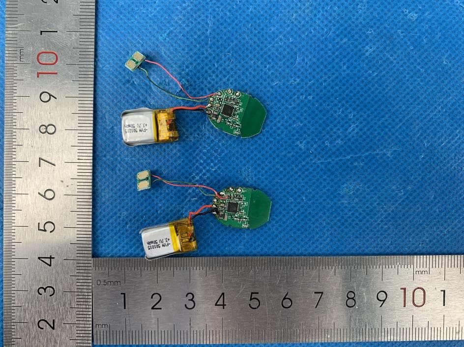
2AS5O-094
Nov 19, 2020Bluetooth Headphone
Equipment Class
DSS - Part 15 Spread Spectrum Transmitter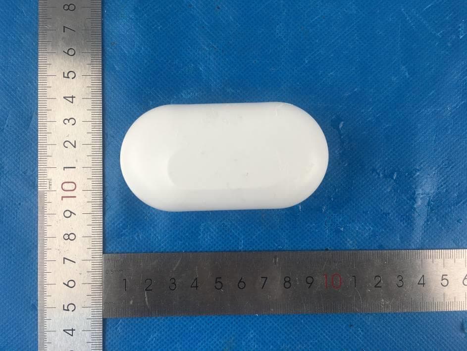
2AS5O-051
Sep 22, 2020True Wireless Earbuds
Equipment Class
DSS - Part 15 Spread Spectrum Transmitter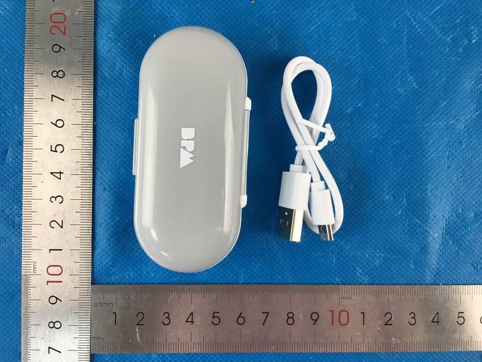
2AS5O-043
Sep 22, 2020True Wireless Earbuds
Equipment Class
DSS - Part 15 Spread Spectrum Transmitter