2AS5O-MC2002-IN-1 WIRELESS MICROPHONE & SPEAKER
China Etech Groups Ltd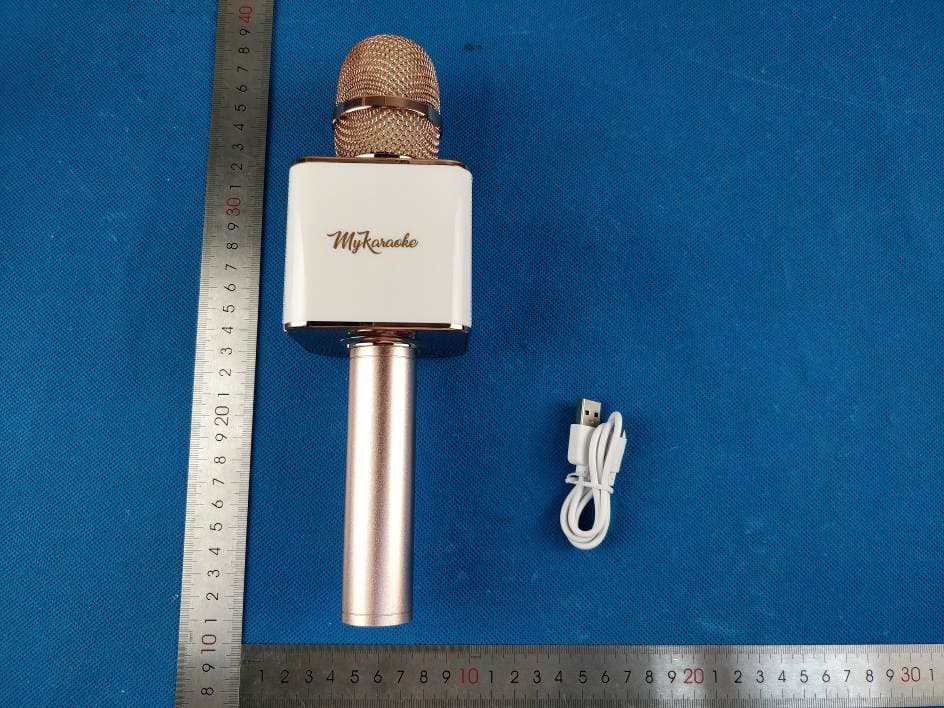
Click to zoom
Application Details
- Equipment Class
- DSS - Part 15 Spread Spectrum Transmitter
- Date of Grant
- Apr 01, 2020
- Application Purpose
- Original Equipment
- Date of Application
- Apr 01, 2020
- Equipment Note
- 2-IN-1 WIRELESS MICROPHONE & SPEAKER
- Frequency Range
- 2402.00000000 - 2480.00000000
- Company
- China Etech Groups Ltd
- Country
- China
Documents & Files
Document Text
Text extracted from the exhibit documents filed with the FCC. Open a document above to read the original.
Users Manual
TREBLEBASS ECHO MUSIC VOLUME MK-MC200 INSTRUCTION MANUAL WORKS WITH MOST KARAOKE APPS! Output: 10W 3W*2 Frequency: 20-18000HZ +/-3dB) S/N: 80dB Speaker: 52mm Speaker Impedance: 4DC 5V 2-IN-1 WIRELESS MICROPHONE & SPEAKER ECHO BASSTREBLE VOLUME MUSIC VOLUME Functions and Sound Effects: Standard Accessories: • Micro USB cable Overview: MyKaraoke P ro is a combination of a wireless Bluetooth speaker and microphone. Use the included Micro USB Cable to charge MyKaraoke Pro: How to charge MyKaraoke Pro: 1. When the battery is too lo w, MyKaraoke Pro will power o ff. 2. Use the included Micro USB Cable to cha rge MyKaraoke Pro via-any USB charger. 3. The LED indicator will light up red while charging and tu rn off when fully charged. Pairing MyKaraoke Pro: 1. Press the button on MyKaraoke Pro to power on the mic rophone. The LED indicator will light up blue with a p rompt tone . This means MyKaraoke P ro is ready to be paired. 2. Turn on your phone or tablet’s Bluetooth setting. 3. Find and select My Karaoke Pro from the device list and wait for the tone. Your mobile device is now pai red with MyKaraoke Pro. 4. See Functions & Sound E ffects to get the best karaoke experience. Download App: Download any karaoke app f rom the iOS App store or Google Play store and play your favorite song. Play: Pick your favorite song in the karaoke app and sing along. Note: If only listening to music, turn the volume switch down on the microphone to minimize feedback/noise. Note: Micro USB charging port is located underneath MyKaraoke Pro. CONFIDENTIAL PRODUCTION ARTWORK DIE CUT DIE FOLD K (BLAC-GRAYSCALE) PLEAS FOLD MANUAL IN THIS ORDER PAPER | SUBSTRAIT CROP SIZE OF DIELINE NOTES & REFERENCES 176.212MM X 234.95MM (6.9375” x 9.25”) 80g Paper LIFEWORKS, LLC. [NEW YORK, NY] DESIGNER: JERMAINE BLUM MODEL# MK-MC200-MANUAL DATE: 07.25.2017 2020© My Karaoke New York, NY 10018 My Karaoke is a registered trademark. All brands are registered trademarks of their respective companies. For technical support call: 877-543-3540 FCC Warning This device complies with part 15 of the FCC Rules. Operation is subject to the following two conditions: (1) This device may not cause harmful interference, and (2) this device must accept any interference received, including interference that may cause undesired operation.Any Changes or modifications not expressly approved by the party responsible for compliance could void the user's authority to operate the equipment. This equipment has been tested and found to comply with the limits for a Class B digital device, pursuant to part 15 of the FCC Rules. These limits are designed to provide reasonable protection against harmful interference in a residential installation. This equipment generates uses and can radiate radio frequency energy and, if not installed and used in accordance with the instructions, may cause harmful interference to radio communications. However, there is no guarantee that interference will not occur in a particular installation. If this equipment does cause harmful interference to radio or television reception, which can be determined by turning the equipment off and on, the user is encouraged to try to correct the interference by one or more of the following measures: -Reorient or relocate the receiving antenna. -Increase the separation between the equipment and receiver. -Connect the equipment into an outlet on a circuit different from that to which the receiver is connected. -Consult the dealer or an experienced radio/TV technician for help.The device has been evaluated to meet general RF exposure requirement. The device can be used in portable exposure condition without restriction.
External Photos
- Page 1 of 4 - Report No.: MTi20022413-1E1-1 Tel:(86-755)88850135 Fax: (86-755) 88850136 Web: http://www.mtitest.com E-mail: [email protected] Address: No.102A & 302A, East Block, Hengfang Industrial Park, Xingye Road, Xixiang, Bao'an District, Shenzhen, Guangdong, China APPENDIX 1: EUT PHOTO Photo 1 (For model MK-MC200) Photo 2 - Page 2 of 4 - Report No.: MTi20022413-1E1-1 Tel:(86-755)88850135 Fax: (86-755) 88850136 Web: http://www.mtitest.com E-mail: [email protected] Address: No.102A & 302A, East Block, Hengfang Industrial Park, Xingye Road, Xixiang, Bao'an District, Shenzhen, Guangdong, China Photo 3 Photo 4 - Page 3 of 4 - Report No.: MTi20022413-1E1-1 Tel:(86-755)88850135 Fax: (86-755) 88850136 Web: http://www.mtitest.com E-mail: [email protected] Address: No.102A & 302A, East Block, Hengfang Industrial Park, Xingye Road, Xixiang, Bao'an District, Shenzhen, Guangdong, China Photo 5 Photo 6 - Page 4 of 4 - Report No.: MTi20022413-1E1-1 Tel:(86-755)88850135 Fax: (86-755) 88850136 Web: http://www.mtitest.com E-mail: [email protected] Address: No.102A & 302A, East Block, Hengfang Industrial Park, Xingye Road, Xixiang, Bao'an District, Shenzhen, Guangdong, China Photo 7 ----END OF REPORT----
ID Label/Location Info
BUTTON 20 mm 41.8 mm 35 mm 9.236 mm 33.3 mm 11.5 mm PANTONE 8402 C PANTONE 8402 C PANTONE 8402 C Made in China Bluetooth Karaoke Microphone SKU: MK-MC200 Input: 5V/500mA Speaker: 3W x 2 Battery: 1200mAh FCC ID: 2AS5O-MC200 Made in China Bluetooth Karaoke Microphone SKU: MK-MC200 Input: 5V/500mA Speaker: 3W x 2 Battery: 1200mAh FCC ID: 2AS5O-MC200 2.5 mm2.5 mm 2.5 mm 2.5 mm 2.5 mm
Internal Photos
- Page 1 of 2 - Report No.: MTi20022413-1E1-1 Tel:(86-755)88850135 Fax: (86-755) 88850136 Web: http://www.mtitest.com E-mail: [email protected] Address: No.102A & 302A, East Block, Hengfang Industrial Park, Xingye Road, Xixiang, Bao'an District, Shenzhen, Guangdong, China APPENDIX 1: EUT PHOTO Photo 1 (For model MK-MC200) Photo 2 - Page 2 of 2 - Report No.: MTi20022413-1E1-1 Tel:(86-755)88850135 Fax: (86-755) 88850136 Web: http://www.mtitest.com E-mail: [email protected] Address: No.102A & 302A, East Block, Hengfang Industrial Park, Xingye Road, Xixiang, Bao'an District, Shenzhen, Guangdong, China Photo 3 Photo 4 ----END OF REPORT---- PCB Antenna
Operational Description
version01 China Etech Groups Ltd Declaration concerning Antenna Specification It is hereby declared that the product Model No.: MK-MC200, K7, MK-MC200AR, MK-BL-MC200AR, MK-MC200DW, MK- BL-MC200AG, MK-MC200B FCC ID: 2AS5O-MC200 fulfills the requirement in FCC test relating to the antenna type. The device specified above confirms to the FCC recommendations for Internal Antenna antenna type(s) described below: Model No. of antenna: N/A Type of antenna: PCB Antenna Gain of the antenna: 5 dBi Frequency range: 2402~2480 MHz The mounting of the antenna is fixed to the radio module and no other antenna should be used. Company name: China Etech Groups Ltd Address: 16/F, Block C, 2nd Phase of Central Avenue, Haihong Industrial Area, Xixiang Road, Baoan District, Shenzhen, China City: Shenzhen ZIP / Postal code: N/A Country: China Contact: Paul Huang Date:2020-03-31 Signature:
RF Exposure Info
RF EXPOSURE REPORT FCC ID: 2AS5O-MC200 Date of issue: Mar. 28, 2020 Report Number: MTi20022413-1E2 Sample Description: 2-IN-1 WIRELESS MICROPHONE & SPEAKER Model(s): MK-MC200, K7, MK-MC200AR, MK-BL-MC200AR, MK- MC200DW, MK-BL-MC200AG, MK-MC200B Applicant: China Etech Groups Ltd Address: 16/F, Block C, 2nd Phase of Central Avenue, Haihong Industrial Area, Xixiang Road, Baoan District, Shenzhen, China Date of Test: Mar. 04, 2020 to Mar. 17, 2020 Shenzhen Microtest Co., Ltd. http://www.mtitest.com - Page 2 of 4- Report No.: MTi20022413-1E2 TEST RESULT CERTIFICATION Applicant’s name: China Etech Groups Ltd Address: 16/F, Block C, 2nd Phase of Central Avenue, Haihong Industrial Area, Xixiang Road, Baoan District, Shenzhen, China Manufacture's name: China Etech Groups Ltd Address: 16/F, Block C, 2nd Phase of Central Avenue, Haihong Industrial Area, Xixiang Road, Baoan District, Shenzhen, China Product name: 2-IN-1 WIRELESS MICROPHONE & SPEAKER Model and/or type reference: MK-MC200 Serial Model: K7, MK-MC200AR, MK-BL-MC200AR, MK-MC200DW, MK-BL-MC200AG, MK-MC200B RF Exposure Procedures: KDB 447498 D01 v06 This device described above has been tested by Shenzhen Microtest Co., Ltd and the test results show that the equipment under test (EUT) is in compliance with the FCC requirements. And it is applicable only to the tested sample identified in the report. Tested by: Danny Xu Mar. 17, 2020 Reviewed by: Leo Su Mar. 28, 2020 Approved by: Tom Xue Mar. 28, 2020 - Page 3 of 4- Report No.: MTi20022413-1E2 1. Standalone SAR test exclusion considerations Unless specifically required by the published RF exposure KDB procedures, standalone 1-g head or body and 10-g extremity SAR evaluation for general population exposure conditions, by measurement or numerical simulation, is not required when the corresponding SAR Test Exclusion Threshold condition(s), listed below, is (are) satisfied. These test exclusion conditions are based on source-based time-averaged maximum conducted output power of the RF channel requiring evaluation, adjusted for tune-up tolerance, and the minimum test separation distance required for the exposure conditions. The minimum test separation distance defined in 4.1 f) is determined by the smallest distance from the antenna and radiating structures or outer surface of the device, according to the host form factor, exposure conditions and platform requirements, to any part of the body or extremity of a user or bystander. To qualify for SAR test exclusion, the test separation distances applied must be fully explained and justified, typically in the SAR measurement or SAR analysis report, by the operating configurations and exposure conditions of the transmitter and applicable host platform requirements, according to the required published RF exposure KDB procedures. When no other RF exposure testing or reporting are required, a statement of justification and compliance must be included in the equipment approval, in lieu of the SAR report, to qualify for SAR test exclusion. When required, the device specific conditions described in the other published RF exposure KDB procedures must be satisfied before applying these SAR test exclusion provisions. a) For 100 MHz to 6 GHz and test separation distances ≤ 50 mm, the 1-g and 10-g SAR test exclusion thresholds are determined by the following: [(max. power of channel, including tune-up tolerance, mW) / (min. test separation distance, mm)] · [√f(GHz)] ≤ 3.0 for 1-g SAR, and ≤ 7.5 for 10-g extremity SAR, where f (GHz) is the RF channel transmit frequency in GHz Power and distance are rounded to the nearest mW and mm before calculation The result is rounded to one decimal place for comparison The values 3.0 and 7.5 are referred to as numeric thresholds in step b) below The test exclusions are applicable only when the minimum test separation distance is ≤ 50 mm, and for transmission frequencies between 100 MHz and 6 GHz. When the minimum test separation distance is < 5 mm, a distance of 5 mm according to 4.1 f) is applied to determine SAR test exclusion. b) For 100 MHz to 6 GHz and test separation distances > 50 mm, the 1-g and 10-g SAR test exclusion thresholds are determined by the following (also illustrated in Appendix B): 1) {[Power allowed at numeric threshold for 50 mm in step a)] + [(test separation distance – 50 mm)·(f(MHz)/150)]} mW, for 100 MHz to 1500 MHz 2) {[Power allowed at numeric threshold for 50 mm in step a)] + [(test separation distance – 50 mm)·10]} mW, for > 1500 MHz and ≤ 6 GHz c) For frequencies below 100 MHz, the following may be considered for SAR test exclusion (also illustrated in Appendix C): 1) For test separation distances > 50 mm and < 200 mm, the power threshold at the corresponding test separation distance at 100 MHz in step b) is multiplied by [1 + log(100/f(MHz))] 2) For test separation distances ≤ 50 mm, the power threshold determined by the equation in c) 1) for 50 mm and 100 MHz is multiplied by ½ 3) SAR measurement procedures are not established below 100 MHz. - Page 4 of 4- Report No.: MTi20022413-1E2 When SAR test exclusion cannot be applied, a KDB inquiry is required to determine SAR evaluation requirements for any SAR test results below 100 MHz to be acceptable. 2. SAR Test Exclucsion Thresholds We use 5mm as separation distance to calculated. Bluetooth DSS: Transmit Frequency (GHz) Mode Measured Power (dBm) Tune-up power (dBm) Max tune- up Result 1g SAR power(dBm) calculation 2.402 GFSK -0.436 0±1 1 0.3902 3 2.441 -0.322 0±1 1 0.3934 3 2.48 -0.666 0±1 1 0.3965 3 2.402 π/4-DQPSK 0.478 1±1 2 0.4913 3 2.441 0.576 1±1 2 0.4952 3 2.48 0.25 1±1 2 0.4992 3 Conclusion: For the max result: 0.4992≤ 3.0 for 1g SAR, No SAR is required. ----END OF REPORT----
Test Report
This test report is valid for the tested samples only. It cannot be reproduced except in full without prior written consent of Shenzhen Microtest Co., Ltd. Tel:(86-755)88850135 Fax: (86-755) 88850136 Web: http://www.mtitest.com E-mail: [email protected] Address: No.102A & 302A, East Block, Hengfang Industrial Park, Xingye Road, Xixiang, Bao'an District, Shenzhen, Guangdong, China Test Report FCC ID: 2AS5O-MC200 Date of issue: Mar. 282020 Report number: MTi20022413-1E1 Sample description: 2-IN-1 WIRELESS MICROPHONE & SPEAKER Model(s): MK-MC200, K7, MK-MC200AR, MK-BL-MC200AR, MK-MC200DW, MK-BL-MC200AG, MK-MC200B Applicant: China Etech Groups Ltd Address: 16/F, Block C, 2nd Phase of Central Avenue, Haihong Industrial Area, Xixiang Road, Baoan District, Shenzhen, China Date of test: Mar. 04, 2020 to Mar. 17, 2020 Shenzhen Microtest Co., Ltd. http://www.mtitest.com - Page 2 of 59 - Report No.: MTi20022413-1E1 Tel:(86-755)88850135 Fax: (86-755) 88850136 Web: http://www.mtitest.com E-mail: [email protected] Address: No.102A & 302A, East Block, Hengfang Industrial Park, Xingye Road, Xixiang, Bao'an District, Shenzhen, Guangdong, China Table of Contents 1 GENERAL INFORMATION ....................................................................................................................................... 5 1.1 DESCRIPTION OF EUT ................................................................................................................................................... 5 1.2 OPERATION CHANNEL LIST .............................................................................................................................................. 5 1.3 TEST CHANNEL LIST ....................................................................................................................................................... 6 1.4 ANCILLARY EQUIPMENT LIST ........................................................................................................................................... 6 1.5 DESCRIPTION OF SUPPORT UNITS .................................................................................................................................... 6 2 SUMMARY OF TEST RESULTS ................................................................................................................................. 7 3 TEST FACILITIES AND ACCREDITATIONS .................................................................................................................. 8 3.1 TEST LABORATORY ........................................................................................................................................................ 8 3.2 ENVIRONMENTAL CONDITIONS ........................................................................................................................................ 8 3.3 MEASUREMENT UNCERTAINTY ........................................................................................................................................ 8 3.4 TEST SOFTWARE ........................................................................................................................................................... 8 4 EQUIPMENT LIST .................................................................................................................................................. 9 5 TEST RESULT ....................................................................................................................................................... 10 5.1 ANTENNA REQUIREMENT ............................................................................................................................................. 10 5.1.1 Standard requirement ....................................................................................................................................... 10 5.1.2 EUT antenna ..................................................................................................................................................... 10 5.2 PEAK OUTPUT POWER ................................................................................................................................................. 11 5.2.1 Limit .................................................................................................................................................................. 11 5.2.2 Test setup .......................................................................................................................................................... 11 5.2.3 Test procedure ................................................................................................................................................... 11 5.2.4 Test results ........................................................................................................................................................ 11 5.3 CONDUCTED EMISSION ................................................................................................................................................ 16 5.3.1 Limits ................................................................................................................................................................. 16 5.3.2 Test setup .......................................................................................................................................................... 16 5.3.3 Test procedure ................................................................................................................................................... 17 5.3.4 Test results ........................................................................................................................................................ 17 5.4 RADIATED SPURIOUS EMISSION ...................................................................................................................................... 23 5.4.1 Limits ..............................................................…
Text truncated - open the document above for the full version.
Test Setup Photos
Model: MK-MC200 Radiated emission Conducted emission
Contact Information
Applicant
Paul Huang(Manger)
Test Firm
Shenzhen Microtest Co., Ltd.Selby Liao
[email protected]0755-88850135-1193
Technical Specifications
| # | Rule Parts | Frequency Range | Power Output |
|---|---|---|---|
| 1 | 15C | 2.40 GHz - 2.48 GHz | 1.20 mW |
Other Applications from China Etech Groups Ltd
2AS5O-EBP-22055
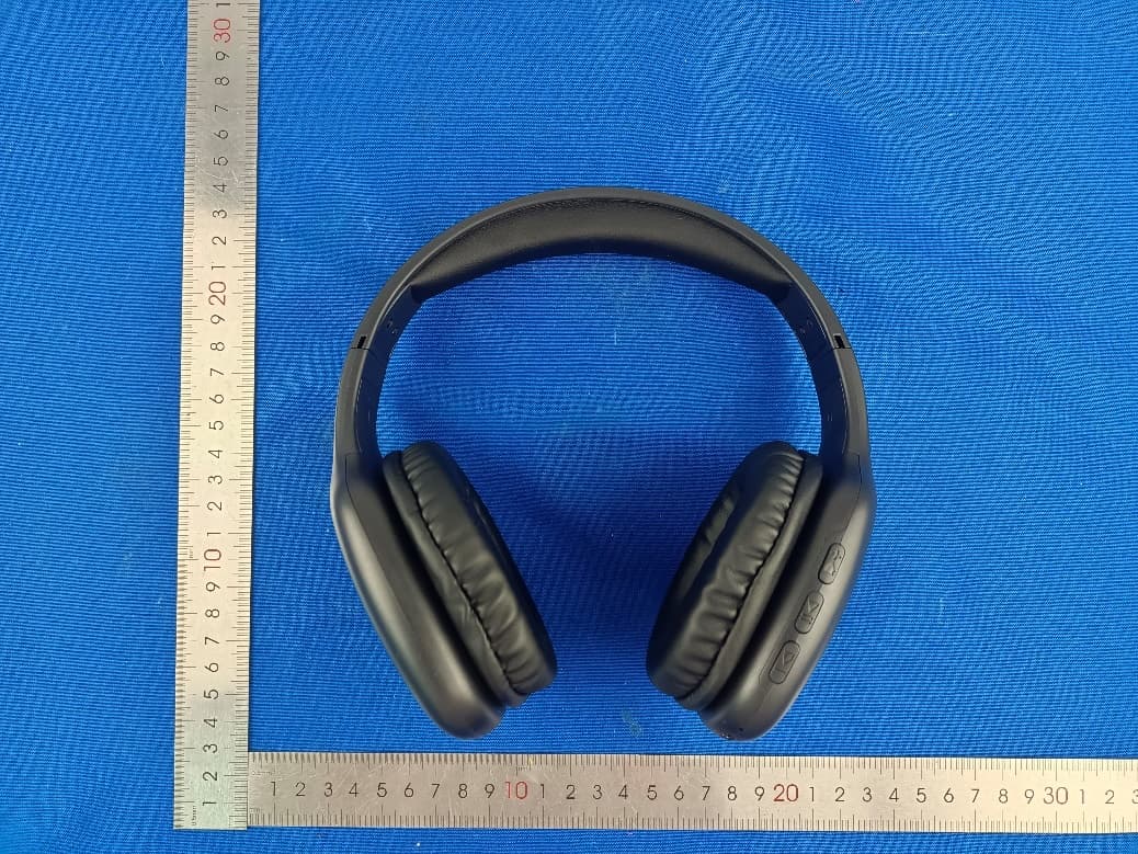
Mar 19, 2023ART + SOUND BT HEADPHONE
Equipment Class
DSS - Part 15 Spread Spectrum Transmitter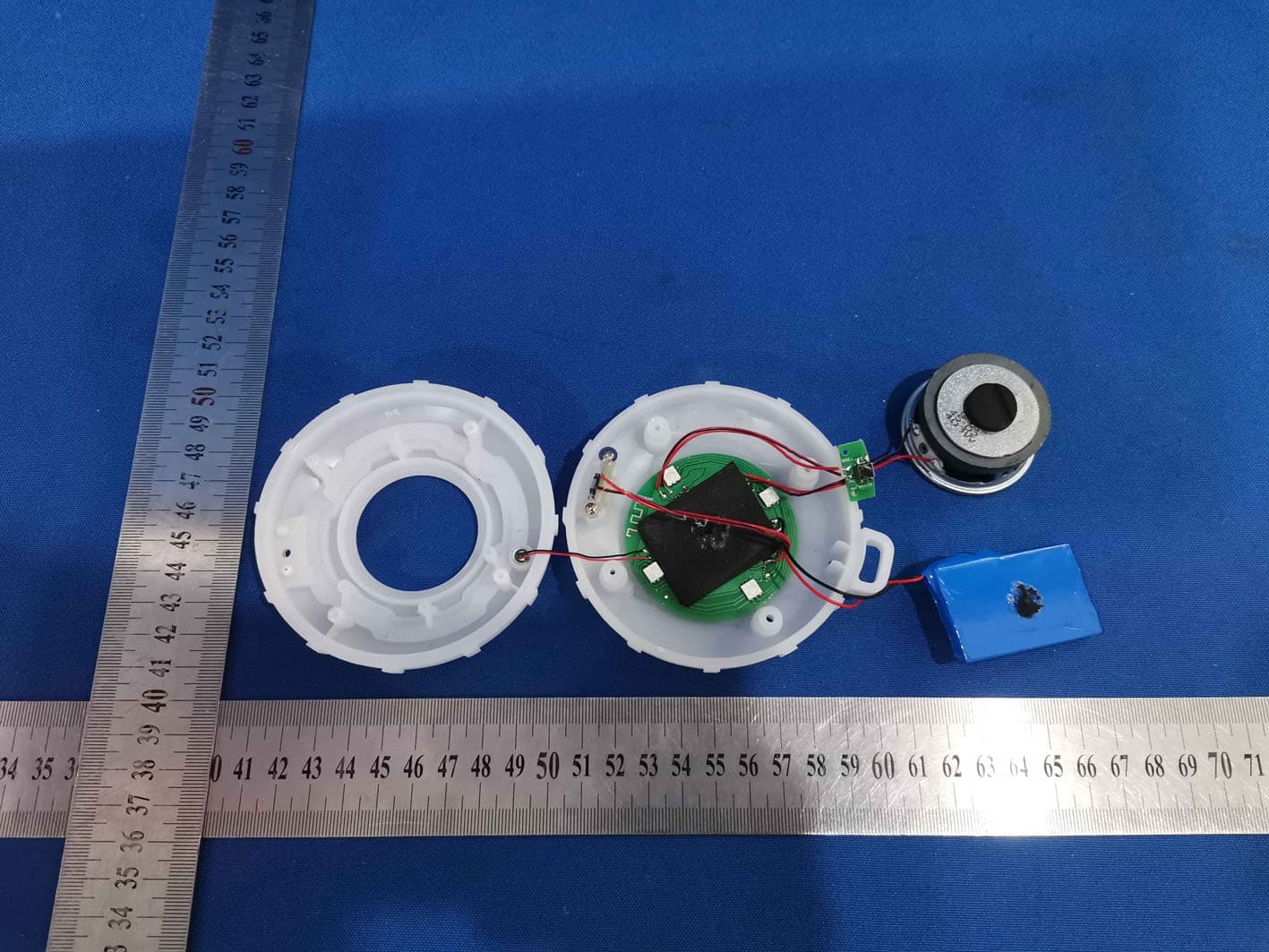
2AS5O-1112B
Nov 03, 2021Fashion Speaker with Colorful Lights
Equipment Class
DSS - Part 15 Spread Spectrum Transmitter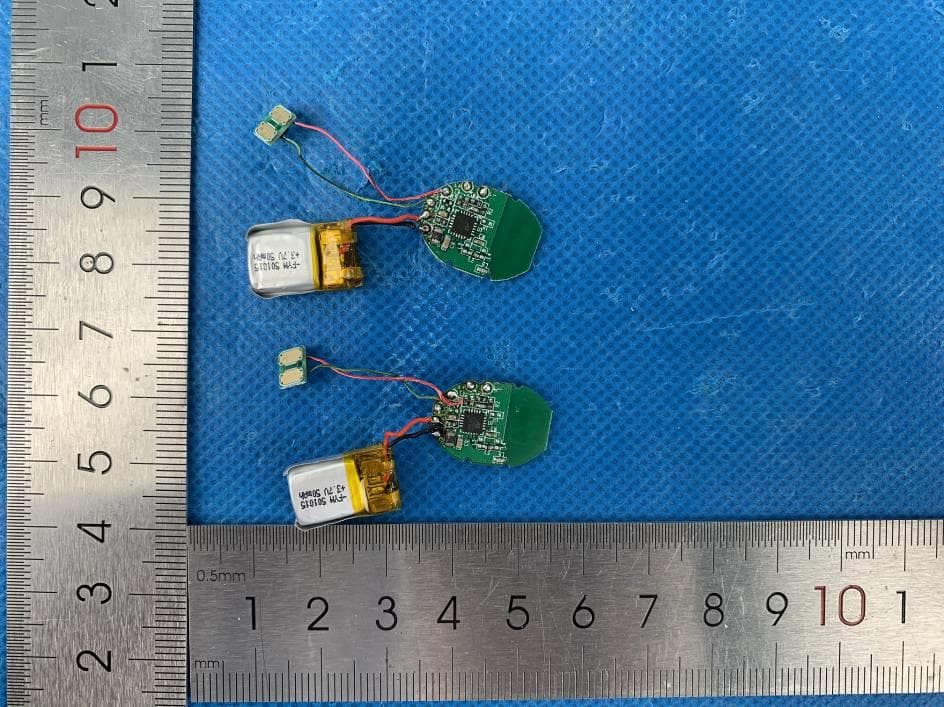
2AS5O-094
Nov 19, 2020Bluetooth Headphone
Equipment Class
DSS - Part 15 Spread Spectrum Transmitter
2AS5O-051
Sep 22, 2020True Wireless Earbuds
Equipment Class
DSS - Part 15 Spread Spectrum Transmitter
2AS5O-043
Sep 22, 2020True Wireless Earbuds
Equipment Class
DSS - Part 15 Spread Spectrum Transmitter