2AS8G-WM20X-SERIES2.4G wireless audio transceiver
SHYH FONG INDUSTRIAL CO., LTD.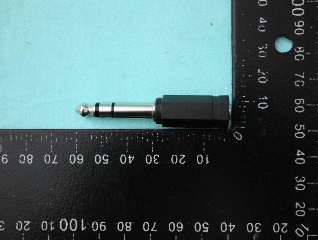
Click to zoom
Application Details
- Equipment Class
- DTS - Digital Transmission System
- Date of Grant
- Sep 21, 2021
- Application Purpose
- Original Equipment
- Date of Application
- Sep 16, 2021
- Equipment Note
- 2.4G wireless audio transceiver
- Frequency Range
- 2401.00000000 - 2475.00000000
- Country
- Taiwan
Documents & Files
Document Text
Text extracted from the exhibit documents filed with the FCC. Open a document above to read the original.
Users Manual
2021-August MACmike WM201 Wireless Microphone System User Manual WM201 is a wireless microphone system with one transmitter/multiple receiver. It’s used for school teaching, live broadcast, vocal recording, camera, lecture, audio guide and others applications. The transmitter and receiver need to be paired to use. The transmitter can be paired with multiple receivers, which is very convenient for live broadcast or recording purposes. Transmitter sound signal can input recording equipment such as mobile phone, camera and computer through different receivers at the same time. Moreover, the receivers can connect earphone for monitor. 2021-August Feature 1. 2.4G ISM band 2. Audio Latency: ≦8ms 3. Use on one transmitter/one receiver or one transmitter/ multiple receivers. 4. Built-In Microphone 5. A 3.5mm Audio In/ Audio Out phone-jack. The transmitter can be connected to audio source device such as condenser mic, mobile phones, computers and so on. The receiver can be connected to earphones, mobile phones, cameras, computers and so on. 6. Rechargeable Li-polymer battery. Compliance with IEC/UL/UN38.3 regulations. 7. Charging by USB Type-C. DC-5V. 8. LCD display battery status, charging status, channel and linking status. 9. Use on waist-hanging, neck-hanging and hand-held. 10. Up to 30 channels, and no interference. Transmitter 1. Power consumption: 100mA(Max.) 2. RF Power: 0~19.5dBm Receiver 1. Power consumption: 20mA (Max.) General 1. Press power-key one second for power on/off. 2. Transmitter press and hold up/down key at the same time to unlock. After unlock, press up/down key to set the working channel. 3. Receiver press up/down key to set the output volume. After setting up, receiver will memorize the volume. Charging 1. USB Type-C 5V 2. If battery is out of energy, try to charging at least 10 minutes and then check the display. If display works then system good, or contact service for battery replace. 3. Notice! When USB voltage higher than 5.5V, it could damage system and battery. 2021-August Display 1. The LCD displays system information. 2. Symbol A means it is a transmitter. 3. Symbol B means it is a receiver. 4. Both symbol A and B means it is a receiver and this receiver is getting data from transmitter. 5. The receiver displays UX to indicate the volume status. (U0 is minimum volume, U9 is maximum volume) 6. Display 00~29 means channel. 7. Transmitter displays ,means the up/down key locked. 8. After transmitter unlock, if no key pressed for 5 seconds, the up/down key will lock again and display. 9. means battery full energy, means battery low, means need to be charged in 30 minutes. 10. After the transmitter is powered on, then green LED will light up. 11. When the transmitter has audio signal, the orange LED light up. 12. After the receiver is powered on, the blue LED will light up. 13. When the receiver has got the pairing signal, all LEDs light up. (blue, red and orange LEDs) Power-Saving 1. When no audio signal input in 20 minutes, the transmitter will power off. 2. When receiver could not get signal from transmitter in 10 minutes, the receiver will power off. In additional WM200 audio signal could output to a. Amplifier (suggestion volume U4) b. Mixer (suggestion volume U3) c. Mobile phone (suggestion volume U5) d. Camera (suggestion volume U3) e. Computer(PC) (suggestion volume U5) f. Headset (suggestion volume U8) 2021-August Advanced 1. The transmitter in power off status, pressed and hold the up/down key then turn on to enter the advanced setting mode a. Display software version 2 seconds. b. PX means radiation power. (P7 is maximum, P0 is minimum. Suggestion P4) c. 00~29 means channels. d. Press power key to save settings or auto-save after 10 seconds. e. After save settings, display OF and system off. 2. The receiver in power off status, pressed and hold the up/down key then turn on to enter the advanced setting mode a. Display software version 2 seconds b. dX means pairing distance. (d9 is farthest, d0 is nearest. Suggestion d3, the pairing distance is around 3 meters.) c. 00~29 means channels d. Press power key to save settings or auto-save after 10 seconds. e. After save settings, display OF and system off. 3. The transmitter in power off status, pressed and hold the up key then turn on to enter the pairing mode. In this mode, the transmitter will send pair signal , LCD display Sd and symbol A/B hopping in 30 seconds. Press power key will terminate this mode immediately. 4. When receiver in charging status and no transmitter signal input(symbol A is dark), pairing mode is working. a. After received pairing signal, the receiver will update and relink to transmitter. b. After received pairing signal, the LEDs (orange/red/blue LEDs) will light up at the same time. c. If symbol A is shown, the receiver will ignore the pairing signal. Trouble shooting 1. When receiver could not connect to transmitter (receiver symbol A always dark). Please try to re-pair. (refer advanced, item 3 and item 4) 2. Intermittent voice a. Refer advanced, item 1. If transmitter radiation power under P5, setting up to P5. If the problem still, try to setting to P7. b. Try to modify transmitter channel. If the channel is 01, then modify it to 11 or 21 and so on. c. If multiple sets of WM201 are used in the same space at the same time, please note the channels should different for avoid interference. 2021-August FCC Interference Statement This equipment has been tested and found to comply with the limits for a Class B digital device, pursuant to Part 15 of the FCC Rules. These limits are designed to provide reasonable protection against harmful interference in a residential installation. This equipment generates, uses and can radiate radio frequency energy and, if not installed and used in accordance with the instructions, may cause harmful interference to radio communications. However, there is no guarantee that interference will not occur in a particular installation. If this equipment does cau…
Text truncated - open the document above for the full version.
External Photos
Photographs of EUT Report No. : EP162317 SPORTON International Inc. Page No. : 1 of 32 EP Report Version : Rev. 01 Issued Date : Sep. 10, 2021 TX Photographs of EUT Report No. : EP162317 SPORTON International Inc. Page No. : 2 of 32 EP Report Version : Rev. 01 Issued Date : Sep. 10, 2021 Photographs of EUT Report No. : EP162317 SPORTON International Inc. Page No. : 3 of 32 EP Report Version : Rev. 01 Issued Date : Sep. 10, 2021 Photographs of EUT Report No. : EP162317 SPORTON International Inc. Page No. : 4 of 32 EP Report Version : Rev. 01 Issued Date : Sep. 10, 2021 Photographs of EUT Report No. : EP162317 SPORTON International Inc. Page No. : 15 of 32 EP Report Version : Rev. 01 Issued Date : Sep. 10, 2021 RX (Wireless Microphone Receiver) Photographs of EUT Report No. : EP162317 SPORTON International Inc. Page No. : 16 of 32 EP Report Version : Rev. 01 Issued Date : Sep. 10, 2021 Photographs of EUT Report No. : EP162317 SPORTON International Inc. Page No. : 17 of 32 EP Report Version : Rev. 01 Issued Date : Sep. 10, 2021 Photographs of EUT Report No. : EP162317 SPORTON International Inc. Page No. : 18 of 32 EP Report Version : Rev. 01 Issued Date : Sep. 10, 2021 Photographs of EUT Report No. : EP162317 SPORTON International Inc. Page No. : 30 of 32 EP Report Version : Rev. 01 Issued Date : Sep. 10, 2021 3.5M Audio Cable Photographs of EUT Report No. : EP162317 SPORTON International Inc. Page No. : 31 of 32 EP Report Version : Rev. 01 Issued Date : Sep. 10, 2021 USB male A to USB Type-C Cable ADP-3.5F to 6.3M Photographs of EUT Report No. : EP162317 SPORTON International Inc. Page No. : 32 of 32 EP Report Version : Rev. 01 Issued Date : Sep. 10, 2021 ─────THE END────
ID Label/Location Info
產品本體後方FCC ID 樣張標示位置 The location of sample of the marking 商品檢驗標識 Commodity Inspection Mark
Internal Photos
Photographs of EUT Report No. : EP162317 SPORTON International Inc. Page No. : 5 of 32 EP Report Version : Rev. 01 Issued Date : Sep. 10, 2021 TX Photographs of EUT Report No. : EP162317 SPORTON International Inc. Page No. : 6 of 32 EP Report Version : Rev. 01 Issued Date : Sep. 10, 2021 Photographs of EUT Report No. : EP162317 SPORTON International Inc. Page No. : 7 of 32 EP Report Version : Rev. 01 Issued Date : Sep. 10, 2021 Photographs of EUT Report No. : EP162317 SPORTON International Inc. Page No. : 8 of 32 EP Report Version : Rev. 01 Issued Date : Sep. 10, 2021 Photographs of EUT Report No. : EP162317 SPORTON International Inc. Page No. : 9 of 32 EP Report Version : Rev. 01 Issued Date : Sep. 10, 2021 Photographs of EUT Report No. : EP162317 SPORTON International Inc. Page No. : 10 of 32 EP Report Version : Rev. 01 Issued Date : Sep. 10, 2021 Photographs of EUT Report No. : EP162317 SPORTON International Inc. Page No. : 11 of 32 EP Report Version : Rev. 01 Issued Date : Sep. 10, 2021 Photographs of EUT Report No. : EP162317 SPORTON International Inc. Page No. : 12 of 32 EP Report Version : Rev. 01 Issued Date : Sep. 10, 2021 Photographs of EUT Report No. : EP162317 SPORTON International Inc. Page No. : 13 of 32 EP Report Version : Rev. 01 Issued Date : Sep. 10, 2021 Photographs of EUT Report No. : EP162317 SPORTON International Inc. Page No. : 14 of 32 EP Report Version : Rev. 01 Issued Date : Sep. 10, 2021 Photographs of EUT Report No. : EP162317 SPORTON International Inc. Page No. : 19 of 32 EP Report Version : Rev. 01 Issued Date : Sep. 10, 2021 RX (Wireless Microphone Receiver) Photographs of EUT Report No. : EP162317 SPORTON International Inc. Page No. : 20 of 32 EP Report Version : Rev. 01 Issued Date : Sep. 10, 2021 Photographs of EUT Report No. : EP162317 SPORTON International Inc. Page No. : 21 of 32 EP Report Version : Rev. 01 Issued Date : Sep. 10, 2021 Photographs of EUT Report No. : EP162317 SPORTON International Inc. Page No. : 22 of 32 EP Report Version : Rev. 01 Issued Date : Sep. 10, 2021 Photographs of EUT Report No. : EP162317 SPORTON International Inc. Page No. : 23 of 32 EP Report Version : Rev. 01 Issued Date : Sep. 10, 2021 Photographs of EUT Report No. : EP162317 SPORTON International Inc. Page No. : 24 of 32 EP Report Version : Rev. 01 Issued Date : Sep. 10, 2021 Photographs of EUT Report No. : EP162317 SPORTON International Inc. Page No. : 25 of 32 EP Report Version : Rev. 01 Issued Date : Sep. 10, 2021 Photographs of EUT Report No. : EP162317 SPORTON International Inc. Page No. : 26 of 32 EP Report Version : Rev. 01 Issued Date : Sep. 10, 2021 Photographs of EUT Report No. : EP162317 SPORTON International Inc. Page No. : 27 of 32 EP Report Version : Rev. 01 Issued Date : Sep. 10, 2021 Photographs of EUT Report No. : EP162317 SPORTON International Inc. Page No. : 28 of 32 EP Report Version : Rev. 01 Issued Date : Sep. 10, 2021 Battery Photographs of EUT Report No. : EP162317 SPORTON International Inc. Page No. : 29 of 32 EP Report Version : Rev. 01 Issued Date : Sep. 10, 2021
RF Exposure Info
~' In ColtDborstion with -TTL s P e a g ~ CALIBRATION LABORATORY Add: No.SI Xueyuan Road, Ha idian District, Beijing, 100191, China Tel: +86-10-62304633-2079 Fax: +86-10-62304633-2504 E -mail: [email protected] http://www.chinattl.cn Client Sporton Certificate No: Z18-60326 CALIBRATION CERTIFICATE Object D2450V2 - SN: 736 Calibration Procedure(s) FF-211-003-01 Calibration Procedures for dipole validation kits Calibration date: August31, 2018 This calibration Certificate documents the traceability to national standards, which realize the physical units of measurements(SI). The measurements and the uncertainties with confidence probability are given on the following pages and are part of the certificate. All calibrations have been conducted in the closed laboratory facility: environment temperature (22±3)"C and humidity<70%. Calibration Equipment used (M&TE critical for calibration) Primary Standards Power Meter NRVD Power sensor NRV-25 Reference Probe EX3DV4 DAE4 Secondary Standards Signal Generator E4438C NetworkAnalyzer E5071 C Calibrated by: Reviewed by: Approved by: ID# 102083 100542 SN 7464 SN 1524 ID# MY49071430 MY46110673 Name Zhao Jing Lin Hao Qi Dianyuan Cal Date(Calibrated by, Certificate No .) Scheduled Calibration 01-Nov-17 (CTTL, No.J17X08756) Oct-18 01-Nov-17 (CTTL, No.J17X08756) Oct-18 12-Sep-17(SPEAG,No.EX3-7464_Sep17) Sep-18 13-Sep-17(SPEAG,No.DAE4-1524_Sep17) Sep-18 Cal Date(Calibrated by, Certificate No.) Scheduled Calibration 23-Jan-18 (CTTL, No.J18X00560) Jan-19 24-Jan-18 (CTTL, No.J18X00561) Jan-19 Function $ ignature SAR Test Engineer ' :·, -~ {!· <.~ SAR Test Engineer .:_--~~:lb SAR Project Leader ~ Issued: September 3, 2018 This calibration certificate shall not be reproduced except in full without written approval of the laboratory. Certificate No: Z I 8-60326 Page I ofs •• ....._, In Collaboration with -TTL s p e a g ~ CALIBRATION LABORATORY Add: No.5 I Xueyuan Road, Haidian District, Beijing, I 00191, China Tel: +86-10-62304633-2079 Fax: +86-10-62304633-2504 E-mai l: [email protected] http://www.chinattl.cn Glossary: TSL ConvF N/A tissue simulating liquid sensitivity in TSL / NORMx,y,z not applicable or not meas ured Calibration is Performed According to the Following Standards: a) IEEE Std 1528-2013, "IEEE Recommended Practice for Determining the Peak Spatial-Averaged Specific Absorption Rate (SAR) in the Human Head from Wireless Communications Devices: Measurement Techniques ", June 2013 b) IEC 62209-1, "Measurement procedure for assessment of specific absorption rate of human exposure to radio frequency fields from hand-held and body-mounted wireless communication devices-Part 1: Device used next to the ear (Frequency range of 300MHz to 6GHz)", July 2016 c) IEC 62209-2, " Procedure to measure the Specific Absorption Rate (SAR) For wireless communication devices used in close proximity to the human body (frequency range of 30MHz to 6GHz)", March 2010 d) KDB865664, SAR Measurement Requirements for 100 MHz to 6 GHz Additional Documentation: e) DASY4/5 Syst em Handbook Methods Applied and Interpretation of Parameters: • Measurement Conditions: Further details are available from the Validation Report at the end of the certificate. All figures stated in the certificate are valid at the frequency indicated. • Antenna Parameters with TSL: The dipole is mounted with the spacer to position its feed point exactly below the center marking of the flat phantom section, with the arms oriented parallel to the body axis. • Feed Point Impedance and Return Loss: These parameters are measured with the dipole positioned under the liquid filled phantom. The impedance stated is transformed from the measurement at the SMA connector to the feed point. The Return Loss ensures low reflected power. No uncertainty required. • Electrical Delay: One-way delay between the SMA connector and the antenna feed point. No uncertainty required. • SAR measured: SAR measured at the stated antenna input power. • SAR normalized: SAR as measured, normalized to an input power of 1 Wat the antenna connector. • SAR for nominal TSL parameters: The measured TSL parameters are used to calculate the nominal SAR result. T he reported uncertainty of measurement is stated as the standard uncertainty of Measurement multiplied by the coverage factor k=2, which for a normal distributi on Corresponds to a coverage probability of approximately 95%. Certificate No: 2 18-60326 Page 2 of8 In Coll11boration with s p e a g CALIBRATION LABORATORY Add: No.SI Xueyuan Road, Haidian District, Beijing, 100191, China Tel: +86-10-62304633-2079 Fax: +86-10-62304633-2504 E-mail: cttl @chinattl.com http://www.chinattl.cn Measurement Conditions DASY fi f svstem con 1Qurabon, as ar as not Q1ven on paQe 1. DASY Version DASY52 Extrapolation Advanced Extrapolation Phantom Triple Flat Phantom 5.1 C Distance Dipole Center -TSL 10mm Zoom Scan Resolution dx, dy, dz= 5 mm Frequency 2450 MHz ± 1 MHz Head TSL parameters Thfll" t dllf e o owinQ oarame ers an ca cu a ions were app11e . r d 52.10.1.1476 with Spacer Temperature Permittivity Conductivity Nominal Head TSL parameters 22.0 °C 39.2 1.80 mho/m Measured Head TSL parameters (22.0 ± 0.2) 0 c 38.8 ± 6 % 1.80 mho/m ± 6 % Head TSL temperature change during test <1.0 °C --- __ ,,,_ SAR result with Head TSL SAR averaged over 1 cm 3 (1 g) of Head TSL Condition SAR measured 250 mW input power 13.2 mW/ g SAR for nominal Head TSL parameters normalized to 1 W 52.7 mW /g ± 18.8 % (k=2) SAR averaged over 10 cm 3 (10 g) of Head TSL Condition SAR measured 250 mW input power 6.17 mW/ g SAR for nominal Head TSL parameters normalized to 1W 24.6 mW /g ± 18.7 % (k=2) Body TSL parameters Th f II . t d I I f e o owing parame ers an ca cu a ions were app 1e . I" d Temperature Permittivity Conductivity Nominal Body TSL parameters 22.0 °C 52.7 1.95 mho/m Measured Body TSL parameters (22.0 ± 0 .2) °C 52.3 ± 6 % 1.98 mho/m ± 6 % Body TSL temperature change during test <1.0 °C ---- ---- SAR It "th B d TSL resu WI o …
Text truncated - open the document above for the full version.
RF Exposure Info
0 dB = 0.280 W/kg = -5.53 dBW/kg Test Laboratory: Sporton International Inc. SAR/HAC Testing Lab Date: 2021/8/5 #01_2.4GHz_SRD Nss1 1TX_Front_0mm_Ch28 Communication System: SRD_Nss1_TX1; Frequency: 2475 MHz;Duty Cycle: 1:1 Medium: HSL_2450_210805 Medium parameters used: f = 2475 MHz; σ = 1.775 S/m; ε r = 38.521; ρ = 1000 kg/m 3 Ambient Temperature:23.5 °C; Liquid Temperature:22.5 °C DASY5 Configuration - Probe: ES3DV3 - SN3169; ConvF(4.47, 4.47, 4.47) @ 2475 MHz; Calibrated: 2021/5/28 - Sensor-Surface: 3mm (Mechanical Surface Detection) - Electronics: DAE3 Sn577; Calibrated: 2020/9/16 - Phantom: SAM_Right; Type: QD000P40CD; Serial: TP:1815 - Measurement SW: DASY52, Version52.10 (4); SEMCAD X Version 14.6.14 (7483) Area Scan (61x91x1): Interpolated grid: dx=1.200 mm, dy=1.200 mm Maximum value of SAR (interpolated) = 0.288 W/kg Zoom Scan (7x7x7)/Cube 0: Measurement grid: dx=5mm, dy=5mm, dz=5mm Reference Value = 9.387 V/m; Power Drift = 0.05 dB Peak SAR (extrapolated) = 0.474 W/kg SAR(1 g) = 0.214 W/kg; SAR(10 g) = 0.090 W/kg Maximum value of SAR (measured) = 0.280 W/kg
RF Exposure Info
Test Laboratory: Sporton International Inc. SAR/HAC Testing Lab Date: 2021/8/5 System Check_Head_2450MHz DUT: D2450V2-736 Communication System: CW; Frequency: 2450 MHz;Duty Cycle: 1:1 Medium: HSL_2450_210805 Medium parameters used: f = 2450 MHz; σ = 1.746 S/m; ε r = 38.618; ρ = 1000 kg/m 3 Ambient Temperature:23.5 °C; Liquid Temperature:22.5 °C DASY5 Configuration - Probe: ES3DV3 - SN3169; ConvF(4.47, 4.47, 4.47) @ 2450 MHz; Calibrated: 2021/5/28 - Sensor-Surface: 3mm (Mechanical Surface Detection) - Electronics: DAE3 Sn577; Calibrated: 2020/9/16 - Phantom: SAM_Right; Type: QD000P40CD; Serial: TP:1815 - Measurement SW: DASY52, Version52.10 (4); SEMCAD X Version 14.6.14 (7483) Pin=50mW/Area Scan (71x71x1): Interpolated grid: dx=1.200 mm, dy=1.200 mm Maximum value of SAR (interpolated) = 3.46 W/kg Pin=50mW/Zoom Scan (7x7x7)/Cube 0: Measurement grid: dx=5mm, dy=5mm, dz=5mm Reference Value = 44.69 V/m; Power Drift = -0.07 dB Peak SAR (extrapolated) = 5.08 W/kg SAR(1 g) = 2.58 W/kg; SAR(10 g) = 1.22 W/kg Maximum value of SAR (measured) = 3.37 W/kg 0 dB = 3.37 W/kg = 5.28 dBW/kg
RF Exposure Info
TEL : 886-3-327-3456 Page 1 of 18 FAX : 886-3-328-4978 Issued Date : Sep. 10, 2021 Template version: 200414 FCC SAR TEST REPORT Report No. : FA162327 FCC SAR TEST REPORT FCC ID : 2AS8G-WM20X-SERIES Equipment : 2.4G wireless audio transceiver Brand Name : MACmike Model Name : WM201 Applicant : SHYH FONG INDUSTRIAL CO., LTD. No. 12, Ln. 57, Dongshun St., Shulin Dist., New Taipei City 238, Taiwan (R.O.C.) Manufacturer : SHYH FONG INDUSTRIAL CO., LTD. No. 12, Ln. 57, Dongshun St., Shulin Dist., New Taipei City 238, Taiwan (R.O.C.) Standard : FCC 47 CFR Part 2 (2.1093) The product was received on Aug 03, 2021 and testing was started from Aug 05, 2021 and completed on Aug 05, 2021. We, SPORTON INTERNATIONAL INC., would like to declare that the tested sample provide by manufacturer and the test data has been evaluated in accordance with the test procedures given in 47 CFR Part 2.1093 and FCC KDB and has been pass the FCC requirement. The test results in this report apply exclusively to the tested model / sample. Without written approval of SPORTON INTERNATIONAL INC. EMC & Wireless Communications Laboratory, the test report shall not be reproduced except in full. Sporton International Inc. EMC & Wireless Communications Laboratory No.52, Huaya 1st Rd., Guishan Dist., Taoyuan City 333, Taiwan Approved by: Cona Huang / Deputy Manager TEL : 886-3-327-3456 Page 2 of 18 FAX : 886-3-328-4978 Issued Date : Sep. 10, 2021 Template version: 200414 FCC SAR TEST REPORT Report No. : FA162327 Table of Contents 1. Statement of Compliance ............................................................................................................................................. 4 2. Guidance Applied .......................................................................................................................................................... 4 3. Equipment Under Test (EUT) Information ................................................................................................................... 4 3.1 General Information ............................................................................................................................................... 4 4. RF Exposure Limits....................................................................................................................................................... 5 4.1 Uncontrolled Environment ...................................................................................................................................... 5 4.2 Controlled Environment .......................................................................................................................................... 5 5. Specific Absorption Rate (SAR) ................................................................................................................................... 6 5.1 Introduction ............................................................................................................................................................ 6 5.2 SAR Definition ........................................................................................................................................................ 6 6. System Description and Setup .................................................................................................................................... 7 6.1 Test Site Location ................................................................................................................................................... 7 6.2 E-Field Probe ......................................................................................................................................................... 8 6.3 Data Acquisition Electronics (DAE) ........................................................................................................................ 8 6.4 Phantom ................................................................................................................................................................. 9 6.5 Device Holder........................................................................................................................................................10 7. Measurement Procedures ...........................................................................................................................................11 7.1 Spatial Peak SAR Evaluation ................................................................................................................................ 11 7.2 Power Reference Measurement............................................................................................................................12 7.3 Area Scan .............................................................................................................................................................12 7.4 Zoom Scan ............................................................................................................................................................13 7.5 Volume Scan Procedures ......................................................................................................................................13 7.6 Power Drift Monitoring ...........................................................................................................................................13 8. Test Equipment List .....................................................................................................................................................14 9. System Verification ......................................................................................................................................................15 9.1 Tissue Verification .................................................................................................................................................15 9.2 System Performance Check Results ............................…
Text truncated - open the document above for the full version.
Test Report
FCC Radio Test Report Report No. : FR162317AZ TEL : 886-3-3273456 Page Number : 1 of 27 FAX : 886-3-3270973 Issued Date : Sep. 16, 2021 Report Template No.: HE1-C11 Ver3.2 Report Version : 02 FCC ID: 2AS8G-WM20X-SERIES FCC Radio Test Report FCC ID : 2AS8G-WM20X-SERIES Equipment : 2.4G wireless audio transceiver Brand Name : MACmike Model Name : WM20xxxxxx (x=A-Z, a-z, 0-9, /, \, blank) Applicant : SHYH FONG INDUSTRIAL CO., LTD. No. 12, Ln. 57, Dongshun St., Shulin Dist., New Taipei City 238, Taiwan (R.O.C.) Manufacturer : SHYH FONG INDUSTRIAL CO., LTD. No. 12, Ln. 57, Dongshun St., Shulin Dist., New Taipei City 238, Taiwan (R.O.C.) Standard : 47 CFR FCC Part 15.247 The product was received on Jun. 24, 2021, and testing was started from Jul. 19, 2021 and completed on Sep. 02, 2021. We, SPORTON INTERNATIONAL INC. Hsinhua Laboratory, would like to declare that the tested sample has been evaluated in accordance with the procedures given in ANSI C63.10-2013 and shown compliance with the applicable technical standards. The test results in this report apply exclusively to the tested model / sample. Without written approval of SPORTON INTERNATIONAL INC. Hsinhua Laboratory, the test report shall not be reproduced except in full. ___________________________________________ Approved by: Allen Lin SPORTON INTERNATIONAL INC. Hsinhua Laboratory No.52, Huaya 1st Rd., Guishan Dist., Taoyuan City 333411, Taiwan (R.O.C.) FCC Radio Test Report Report No. : FR162317AZ TEL : 886-3-3273456 Page Number : 2 of 27 FAX : 886-3-3270973 Issued Date : Sep. 16, 2021 Report Template No.: HE1-C11 Ver3.2 Report Version : 02 FCC ID: 2AS8G-WM20X-SERIES Table of Contents HISTORY OF THIS TEST REPORT .................................................................................................................. 3 SUMMARY OF TEST RESULT ......................................................................................................................... 4 1 GENERAL DESCRIPTION .................................................................................................................... 5 1.1 Information .............................................................................................................................................. 5 1.2 Testing Applied Standards ..................................................................................................................... 7 1.3 Testing Location Information .................................................................................................................. 7 1.4 Measurement Uncertainty ...................................................................................................................... 7 2 TEST CONFIGURATION OF EUT......................................................................................................... 8 2.1 Test Channel Mode ................................................................................................................................ 8 2.2 The Worst Case Measurement Configuration ........................................................................................ 9 2.3 Accessories .......................................................................................................................................... 10 2.4 Support Equipment ............................................................................................................................... 10 2.5 Test Setup Diagram ............................................................................................................................. 11 3 TRANSMITTER TEST RESULT .......................................................................................................... 15 3.1 AC Power-line Conducted Emissions .................................................................................................. 15 3.2 DTS Bandwidth..................................................................................................................................... 17 3.3 Maximum Conducted Output Power .................................................................................................... 18 3.4 Power Spectral Density ........................................................................................................................ 20 3.5 Emissions in Non-restricted Frequency Bands .................................................................................... 21 3.6 Emissions in Restricted Frequency Bands ........................................................................................... 22 4 TEST EQUIPMENT AND CALIBRATION DATA ................................................................................ 26 APPENDIX A. TEST RESULTS OF AC POWER-LINE CONDUCTED EMISSIONS APPENDIX B. TEST RESULTS OF DTS BANDWIDTH APPENDIX C. TEST RESULTS OF MAXIMUM CONDUCTED OUTPUT POWER APPENDIX D. TEST RESULTS OF POWER SPECTRAL DENSITY APPENDIX E. TEST RESULTS OF EMISSIONS IN NON-RESTRIC…
Text truncated - open the document above for the full version.
Contact Information
Applicant
Chih-Yu Yu(Manager)
Test Firm
Sporton International Inc. Hsinhua LaboratoryAlex Chen
Technical Specifications
| # | Rule Parts | Frequency Range | Power Output |
|---|---|---|---|
| 1 | 15C | 2.40 GHz - 2.48 GHz | 55.50 mW |