2ASCM-PBR-14D14 Channel Receiver
PowerBox-Systems GmbH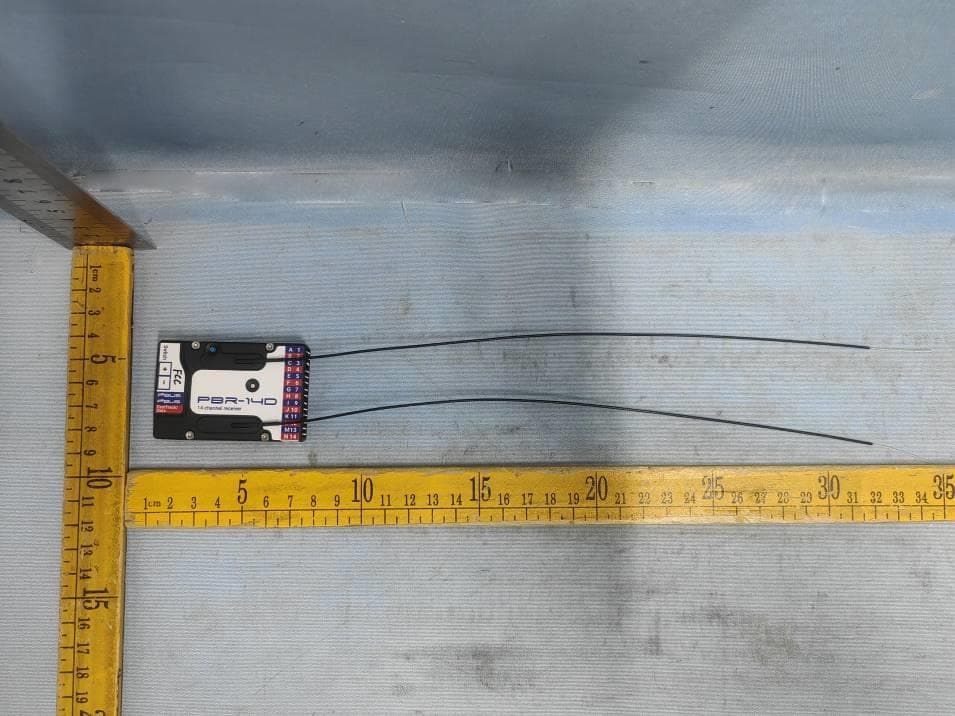
Click to zoom
Application Details
- Equipment Class
- DSS - Part 15 Spread Spectrum Transmitter
- Date of Grant
- Dec 03, 2023
- Application Purpose
- Original Equipment
- Date of Application
- Dec 03, 2023
- Equipment Note
- 14 Channel Receiver
- Frequency Range
- 2402.00000000 - 2467.00000000
- Company
- PowerBox-Systems GmbH
- Country
- Germany
Documents & Files
Document Text
Text extracted from the exhibit documents filed with the FCC. Open a document above to read the original.
Users Manual
Instruction Manual PBr-14d 2 PowerBox-Systems − World Leaders in RC Power Supply Systems Dear PowerBox customer, We are delighted that you have decided to purchase a PBR-14D transceiver, which almost certainly represents the most highly developed and most advanced transmitting and receiving system for your valuable models available anywhere in the modelling world. Unprecedented range in the 2.4 GHz band, and ultra-fast, ultra-precise data transfer in both directions - these are the outstanding features of this radio system. 1. PRODUCT DESCRIPTION If you study the specifications closely, it is clear that PowerBox receivers are by no means “receivers” in the usual sense; they are “transceivers”. They are capable of transmitting and receiving at the same data rate and the same range as the associated system transmitter. All PowerBox transceivers feature a radio chip, but an essential difference is the integral pre-amplifier, which is one of the factors which make the system’s extremely long range possible. The PowerBox radio link is a hopping system which uses at least 66 of 198 possible channels. An intelligent hopping sequence is employed, ensuring interference-free operation even when the frequency band is heavily used. The suffix D, S/XS or SL indicates the number of radio units installed in the transceiver. The D types PBR-9D and PBR-26D incorporate two fully independent receive / transmit units. Other systems feature two aerials, switching between them 50-50, but if one ae- rial loses the signal, 50% of the information is inevitably lost; our design does not www.powerbox-systems.com3 suffer that drawback. There are also no switching diodes which have a damping effect on the signal as it arrives; this has a particularly adverse effect on the radio chip. In contrast, both the receive units in PowerBox transceivers pick up the data packet in undamped form, and subject it to a full analysis. If one of the two pa- ckets contain errors, or if the signal strength is poor, or if the signal is completely absent, the data packet picked up by the other receive unit is used, and passed to the servo outputs or digital outputs. The result is a 100% signal even if one aerial is completely blocked. As of software version 3.5 it is possible to connect a supplementary receiving unit, such as the PBR-26XS, to the FastTrack socket of receiver types PBR7S, PBR9D and PBR10SL. If the primary receiver should receive no data from its inte- gral aerials, the gap is filled seamlessly with the data from the “satellite receiver”. A further important feature is the integral iGyro system. The PBR-7S, PBR-9D, PBR-10SL and PBR-26D receivers have the iGyro software installed as standard, providing control of six separate axes. To make use of the iGyro all you have to do is connect an iGyro SAT to the FastTrack socket. If the integrated iGyro detects a GPSIII or a PBS-TAV sensor on the P²-BUS, the gyro gain is even speed-com- pensated! All iGyro settings can be adjusted conveniently from the transmitter using the Telemetry menu. All PBR receivers are capable of generating various BUS signals at the FastTrack socket, in order to maintain compatibility with third-part products such as heli- copter gyros. In addition to S.BUS and SRXL, as of Version 3.5 an analogue PPM signal can also be available. 4 PowerBox-Systems − World Leaders in RC Power Supply Systems One feature which is unique in the market is the facility to update receivers from the transmitter. You do not even need to remove the receiver or receivers from the model, or connect to the model using a laptop and USB interface, in order to update the receiver software. 2. FEATURES AND CONNECTIONS • 2.4 GHz transceiver matching the PowerBox radio control system • One or two receive units • Extreme interference rejection • Integral electronic switch for more than 20A • Switch function optionally using integral push-button or external MicroSwitch • Ultra-long range • Integrated high-performance six-axis iGyro software • iGyro system with speed-compensation • High-performance real-time telemetry transfers 800 values/second • Integral telemetry for reception quality and battery voltage • Various Bus systems for compatibility with third-party products • Receiver updates from the transmitter • Compact format www.powerbox-systems.com5 3. POWER SUPPLY Power is supplied to the PBR-14D via the MPX high-current socket. Since there is an integral electronic switch, no additional external components are required. The PBR-14D can be switched on and off using either the integral blue push-button, or a separately available MicroSwitch (#3584) or MicroMag (#3585). PWM outputs FastTrack/data connection 2x P²-BUS telemetry and servo port Push-button for electronic switch MPX high-current socket Socket for external MicroSwitch LED 6 PowerBox-Systems − World Leaders in RC Power Supply Systems This is the switching process: hold the push-button pressed in for about two seconds, release the button briefly, then press it a second time briefly to confirm the switching process. If you use the internal push-button, there is no visible indication of the switching process, but you will see the switched status from the LED which shows the receiver’s status. If you use the external MicroSwitch or the MicroMag magnet switch, you will also see the switched status from the switch’s integral LED. 4. BINDING The transceivers can be bound using either of two methods: a) Connect the transceiver first The LED now flashes rapidly for about ten seconds. Press “Bind” at the trans- mitter, and the transmitter and receiver are bound. If you do not press Bind within ten seconds, the receiver LED switches to a slower flashing rate. At this point the receiver can no longer be bound to the transmitter unless the power supply is first disconnected. b) Press “Bind” at the transmitter first After this you connect the receiver to a power supply: the transmitter now binds with the receiver. 5. DETAILED DESCRIPTION OF…
Text truncated - open the document above for the full version.
Attestation Statements
FRN:0028071421 2220 CR 210 W– Suite 108-515, St. Johns, FL 32259, United States
Cover Letter(s)
2ASCM-PBR-14D
External Photos
Picture 1 Picture 2 ANT 1 ANT 2 Picture 3 Picture 4 Picture 5 Picture 6
ID Label/Location Info
A B C D E F G H I J K L M N 1 2 3 4 5 6 7 8 9 10 11 12 13 14 F ast T r ack/ h c t i w S Data www.powerbox-systems.com Model No.: PBR-14D IC: 24594 -PBR14D Made in Germany FCC ID: 2ASCM-PBR-14D
Internal Photos
Picture 1 Picture 2 Picture 3 Picture 4 Picture 5 Picture 6 Picture 7
RF Exposure Info
RF Exposure Requirements 1 General Information Client Information Applicant ....................................... : PowerBox-Systems GmbH Address of applicant ................... : Ludwig-Auer-Strasse 5 Donauwörth, 86609 Germany Manufacturer ................................. : The same as above Address of manufacturer ............. : The same as above General Description of E.U.T FCC ID ............................................ : 2ASCM-PBR-14D Product Name ............................... : 14 Channel Receiver Model No. ..................................... : PBR-14D Model Description ........................ : --- Rated Voltage................................ : DC 4V-9V, max.100 mW Battery Capacity ........................... : --- Power Adapter .............................. : --- Technical Characteristics of EUT Frequency Range ......................... : 2402-2467MHz RF Output Power .......................... : 10.524dBm (Conducted) for ANT 1 10.642dBm (Conducted) for ANT 2 Modulation .................................... : MSK Data Rate ....................................... : 1Mbps Quantity of Channels ................... : 66 Channel Separation ...................... : 1MHz Type of Antenna ........................... : External Antenna Antenna Gain ................................ : 0.65dBi 2 Applicable Standard According to FCC Rule Part 1.1307 (b)(3)(i)(C) and KDB 447498 D04 v01: The minimum separation distance (R in meters) from the body of a nearby person for the frequency (f in MHz) at which the source operates, the ERP (watts) is no more than the calculated value prescribed for that frequency. The table applies to any RF source (i.e., single fixed, mobile, and portable transmitters) and specifies power and distance criteria for each of the five frequency ranges used for the MPE limits. RF Source Frequency (MHz) Minimum Distance Threshold ERP (W) λ L /2π λ H /2π 0.3-1.34 159 m-35.6 m 1,920 R 2 1.34-30 35.6m-1.6m 3,450 R 2 /f 2 30-300 1.6 m-159 mm 3.83 R 2 300-1,500 159 mm-31.8 mm 0.0128 R 2 f 1,500-100,000 31.8mm-0.5mm 19.2 R 2 R must be at least λ/2π, where λ is the free-space operating wavelength in meters. For Multiple RF sources: FCC Rule Part 1.1307(b)(3)(ii): (A) The available maximum time-averaged power of each source is no more than 1 mW and there is a separation distance of two centimeters between any portion of a radiating structure operating and the nearest portion of any other radiating structure in the same device, except if the sum of multiple sources is less than 1 mW during the time-averaging period, in which case they may be treated as a single source (separation is not required). (B) In the case of fixed RF sources operating in the same time-averaging period, or of multiple mobile or portable RF sources within a device operating in the same time averaging period, if the sum of the fractional contributions to the applicable thresholds is less than or equal to 1 as indicated in the following equation. 3 Calculation Result For Single RF Source Radio Access Technology Min. Frequency (MHz) Max. Output Power (dBm) Max. Tune-up Output Power (dBm) Antenna Gain (dBi) Min. Distance (cm) Max. Tune-up ERP Limit Threshold (mW) (dBm) (mW) MSK ANT 1 2402 10.524 11 0.65 20 9.50 8.91 768 MSK ANT 2 2402 10.642 11 0.65 20 9.50 8.91 768 Result: Pass For Multiple RF Sources (Simultaneous Operations) Radio Access Technology Min. Frequency (MHz) Max. Tune- up ERP (mW) Limit Threshold (mW) Simultaneous Ratio Sum of ratios Limit of Ratios - - - - - - - Note: ANT 1 and ANT 2 cannot simultaneous transmission. Note: 1. EIRP= Output Power + Antenna gain; ERP=EIRP-2.15dB 2. Ratio= Tune-Up ERP(mW)/ Exposure Limit (mW) ======End of Report======
Test Report
ReportNo.:RFI-LAB-RF-202310-JJ04-1 QP030-E41 Page1of9 TestingReport CustomerName:PowerBox-SystemsGmbH ProductName:14Channel2.4GHzReceiver SampleModel:PBR-14D ReferenceStandard:GB/T9410-2008;ANSI/IEEEStd149-2021 IssueDate:2023.10.11 Engineer:Date: Auditor:Date: Approver:Date: ReportNo.:RFI-LAB-RF-202310-JJ04-1 QP030-E41 Page2of9 Version VersionNo.DateDescriptionFormulateApproval A02023.10.11Forthefirsttime,formulateZkrisEason Contents 1.GeneralInformation.........................................................................................................................3 1.1Generalinformationoftestinginstitutions...........................................................................3 1.2Testingprinciple...................................................................................................................3 1.3Testequipment......................................................................................................................4 1.4Testenvironment...................................................................................................................4 1.5Statement..............................................................................................................................4 2.SampleInformation.........................................................................................................................5 2.1Clientinformation.................................................................................................................5 2.2DescriptionofEUT(S)..........................................................................................................5 2.3EUTappearance....................................................................................................................6 2.4EUTsetupphotooffreespaceOTAtesing..........................................................................6 3.TestResults......................................................................................................................................7 3.1Teststandard.........................................................................................................................7 3.2Testuncertainty.....................................................................................................................7 3.3Testdata................................................................................................................................7 3.3.1Typicalfreespaceefficiencyandgain......................................................................7 3.3.2Typicalfreespaceradiationpattern...........................................................................8 (Thefollowingisblank)................................................................................................................9 ReportNo.:RFI-LAB-RF-202310-JJ04-1 QP030-E41 Page3of9 1.GeneralInformation 1.1Generalinformationoftestinginstitutions Name ShenzhenRFI-LABCommunicationTechnologyCo.,Ltd. Address 10/FA,LingyunBld,LiufangRd,BaoanDistrict,SZ Tel / E-mail / Equipment AlltheequipmentusedinthereportisfixedinZoneB,WestSideof1/F,Building1, TingweiIndustrialPark,No.6LiufangRoad,Bao'anDistrict,Shenzhen 1.2Testingprinciple ReportNo.:RFI-LAB-RF-202310-JJ04-1 QP030-E41 Page4of9 1.3Testequipment EquipmentModelNo.SerialNo.Manufacturer Calibration date Next calibration date OTATest System RayZone-5000 RFI-LAB-RF -D00 GTS2023.3.142025.3.13 Network Analyzer E5071C RFI-LAB-RF -D01 KEYSIGHT2023.5.112024.5.10 Network Analyzer E5071C RFI-LAB-RF -C02 KEYSIGHT2023.5.112024.5.10 1.4Testenvironment Temperature 23.6°C Humidity 57%RH Pressure 100.14kPa 1.5Statement (1)Thetestresultsinthereportareonlyapplicabletothetestedsamplesandthetestedsamples workundertheenvironmentdescribedinthereport. (2)OnlyShenzhenRFI-LABCommunicationTechnologyCo.,Ltd.havetherighttomodifythe report,andthemodificationinformationshallbeannotatedintherevisionform. (3)Anyobjectiontothisreportshallberaisedwithin30daysafterformalconfirmationofthe report. (4)Thisreportisinvalidifthereisanyevidencethatthesampleinformationprovidedisfalsified. (5)Thereportisinvalidwithoutthesignatureoftheauditorandapprover. ReportNo.:RFI-LAB-RF-202310-JJ04-1 QP030-E41 Page5of9 2.SampleInformation 2.1Clientinformation Name PowerBox-SystemsGmbH Address Ludwig-Auer-Strasse5Donauwörth,86609Germany Contacts / Tel / E-mail / Manufacturer / 2.2DescriptionofEUT(S) ProductName 14Channel2.4GHzReceiver SampleModel PBR-14D AntennaSize / SerialNo. / AntennaType ExternalAntenna TestItem Antennagain;Efficiency;Radiationpattern FrequencyRange 2400-2500MHz ReceivedDate 2023.10.9 TestDate 2023.10.10 Remark / ReportNo.:RFI-LAB-RF-202310-JJ04-1 QP030-E41 Page6of9 2.3EUTappearance 2.4EUTsetupphotooffreespaceOTAtesing Planform Frontview ReportNo.:RFI-LAB-RF-202310-JJ04-1 QP030-E41 Page7of9 3.TestResults 3.1Teststandard NameParameterMethodStandardno. Mobile communication antenna Antennagain Genericspecification forantennasusedinthe mobilecommunications GB/T 9410-2008 Radiationpattern Antenna Radiationefficiency IEEEStandardTest ProceduresforAntennas ANSI/IEEEStd 149-2021 Gainanddirectivity 3.2Testuncertainty TheuncertaintywascalculatedonthebasisoftheGUMpublishedbyISO,usingthe inclusionfactorofK=2andthe95%confidenceleveltoexpresstheextended uncertainty. ItemUncertainty VSWR±0.3 Antennagain±0.72dB Radiationefficiency±0.72dB 3.3 Testdata 3.3.1Typicalfreespaceefficiencyandgain Frequency/MHz 24002410242024302440245024602470248024902500 PeakGain/dBi -0.39-0.57-0.58-0.35-0.21-0.220.310.650.600.780.95 Efficiency/% 26.8426.2925.9127.4328.5728.3130.9733.0232.2032.9233.50 ReportNo.:RFI-LAB-RF-202310-JJ04-1 QP030-E41 Page8of9 3.3.2Typicalfreespaceradiationpattern (1)X-ZPlane(unit:dBi): (2)Y-ZPlane(unit:dBi): ReportNo.:RFI-LAB-RF-202310-JJ04-1 QP030-E41 Page9of9 (3)X-YPlane(unit:dBi): (4)TypicalFreeSpace3DRadiationPatternat2.5GHz(unit:dBi): -------------------------------------------------End------------------------------------------------ (Thefollow…
Text truncated - open the document above for the full version.
Test Setup Photos
Test Setup For Radiated Emission (30MHz to 1GHz) Test Setup For Radiated Emission (Above 1GHz)
Contact Information
Applicant
Richard Deutsch
Test Firm
Waltek Testing Group (Foshan) Co. Ltd.Winnie Huang
[email protected]+86-757-23811398
Technical Specifications
| # | Rule Parts | Frequency Range | Power Output |
|---|---|---|---|
| 1 | 15C | 2.40 GHz - 2.47 GHz | 11.60 mW |
Other Applications from PowerBox-Systems GmbH
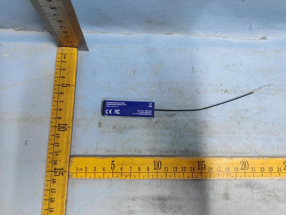
2ASCM-PBR-010SL
Aug 23, 2023PBR-10SL
Equipment Class
DSS - Part 15 Spread Spectrum Transmitter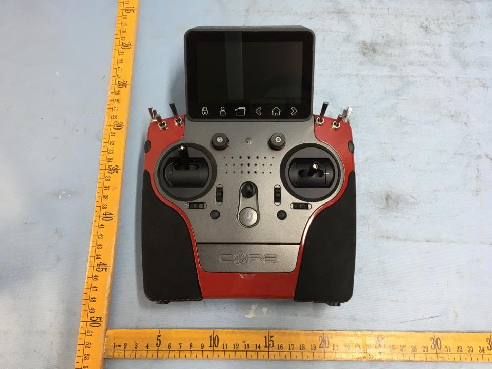
2ASCM-PBXATOM
Aug 13, 2022Radio System ATOM
Equipment Class
DSS - Part 15 Spread Spectrum Transmitter