2ASDTVR47Retro Wooden Radio
ClearClick Software LLC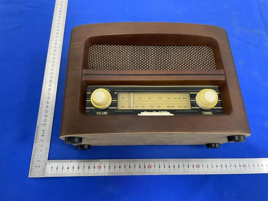
Click to zoom
Application Details
- Equipment Class
- DSS - Part 15 Spread Spectrum Transmitter
- Date of Grant
- Apr 26, 2021
- Application Purpose
- Original Equipment
- Date of Application
- Apr 26, 2021
- Equipment Note
- Retro Wooden Radio
- Frequency Range
- 2402.00000000 - 2480.00000000
- Company
- ClearClick Software LLC
- Country
- United States
Documents & Files
Document Text
Text extracted from the exhibit documents filed with the FCC. Open a document above to read the original.
Users Manual
1 ClearClick ® Retro Wooden Radio with BT (Model VR47) Quick Start Guide & User’s Manual 5-Year Warranty + FREE USA-Based Tech Support If you have any issue or question regarding this product, contacting us directly is the fastest way to resolve the issue. We are ClearClick®, a small USA-based business, and we stand behind our products with a 5-year warranty & free USA tech support. If you have any issues with our product, please contact us at [email protected]. www.ClearClick.tech 2 Extend Your Warranty for FREE! Extend your warranty by one year for free simply by registering your product at: www.ClearClick.tech Safety Precautions 1. Do not disassemble the unit. 2. Do not operate the unit around water or rain. Do not operate the unit around any kind of machines or appliances (other than computers). 3. Turn off and unplug the unit when not in use. 4. Do not allow young children to use this device. Thank You! Thank you for your purchase of the ClearClick® Retro Wooden Radio! (Model VR47) We appreciate your business. At ClearClick®, we try to make our technology as clear to understand and use as possible. But if you get stuck at any point, you qualify for FREE USA-based tech support as a ClearClick® customer. Just email us at: [email protected] (Make sure you explain your issue in detail and tell us that you’re using our ClearClick® Retro Wooden Radio - Model Number VR47). Our USA-based tech support team members will normally reply to you within 24-48 business hours.) 3 QUICK START – Setting Up The Device 1. Securely plug the power plug into a power outlet. Important Note For Users Outside USA, Canada, and Mexico: This device is ONLY compatible with standard North American 110V-120V voltage. Do NOT use with voltages over 110V-120V, as this will permanently damage the device instantly! 2. Turn on the radio with the power switch on the right side. 3. The device will start up in either “radio” or “Bluetooth” mode, whichever it was set on during last use. (NOTE: If you have a 3.5mm aux-in cable plugged in, or have the USB function turned on, these functions will take priority) QUICK START – Listening To AM/FM Radio 1. If you previously had an aux-in/line-in cable connected, make sure it is disconnected to use the radio. 2. If you previously had a USB drive connected, unplug it and turn off the USB function in the rear of the radio. 3. Make sure the device is in “radio” mode by pressing the “RADIO/BT” button until a light illuminates under the “AM” or “FM button. 4. Switch between “AM” and “FM” by using the “AM” and “FM” buttons. 4 5. Use the tuning knob to select your desired radio station. 6. Use the volume control knob to adjust the volume. Note: To improve the reception of FM radio, simply adjust the pigtail antenna in the back of the radio. To improve the reception of AM radio, simply adjust the position of the entire radio. QUICK START – Playing Music via Bluetooth 1. If you previously had an aux-in/line-in cable connected, make sure it is disconnected to use Bluetooth. 2. If you previously had a USB drive connected, unplug it and turn off the USB function in the rear of the radio. 3. Make sure the radio is in “Bluetooth” mode by pressing the “RADIO/BT” button until a white/purple light illuminates under the “RADIO/BT” button. 4. On your phone, tablet, or computer, search for the Bluetooth device named “Vintage Radio VR47.” Connect to this device. 5. Start playing music on your phone, tablet, or computer. 6. Use the volume control knob on the radio to adjust the volume. (Note: You may also need to adjust the volume on your phone or tablet.) 5 QUICK START – Playing Music via Line-In/Aux-In 1. Using the included 3.5mm-to-3.5mm aux cable, connect your phone, tablet, or MP3 player to the radio’s “AUX-IN” jack in the back of the device. 2. Start playing music on your phone, tablet, or MP3 player. 3. Use the volume control knob on the radio to adjust the volume. (Note: You may also need to adjust the volume on your phone or tablet.) 4. NOTE: You must unplug the aux-in cable when you want to use the radio’s USB, AM/FM, or Bluetooth functions again. QUICK START – Playing Music via USB Drive 1. If you previously had an aux-in/line-in cable connected, make sure it is disconnected to use USB. 2. Press the USB ON/OFF button in the rear of the unit. 3. Insert a USB flash drive containing MP3 or WMA audio files. (NOTE: 32GB MAX USB DRIVE). The unit will start playing the first song on the drive automatically. 4. To select a song, press the Forward or Back butons. 5. To pause or resume playback, press Play/Pause button. 6 6. To stop playback, press USB ON/OFF button. 7. NOTE: Make sure the radio’s USB on/off button is turned off to use the radio’s AM/FM or Bluetooth functions again. 7 Radio Diagram & Features 1. Volume Knob 2. FM Tuning Display 3. AM Tuning Display 4. AM Function Button 5. FM Function Button 6. RADIO/BT Button (Press to switch back and forth between Radio & Bluetooth modes) 7. Tuning Knob 8. Speaker 8 9. USB ON/OFF Button (Must be turned off to use Radio/Bluetooth) 10. USB Backward Skip Button 11. USB Play/Pause Button 12. USB Forward Skip Button 13. USB Indicator Light 14. USB Port 15. FM Wire Antenna 16. AC Power Cord (110V-120V North American voltage ONLY!) 17. 3.5mm AUX IN Jack 18. POWER Switch 9 Troubleshooting 1. There’s a flashing white light, and the radio won’t switch to “AM” or “FM" radio mode. To listen to “AM” or “FM” radio, you need to switch to “Radio” mode first. Press the “RADIO/BT” button until either the “AM” or “FM” light is illuminated. 2. My radio was working, but now won’t play anything, radio or Bluetooth. Make sure you have disconnected any aux-in cables from the “aux-in” jack in the back of the radio. Make sure the USB function (in the rear of the radio) is turned off. 3. In Bluetooth or aux-in mode, the radio’s volume is turned up all the way, but the sound isn’t loud enough. Make sure you have turned up the volume on your phone, tablet, or MP3 play…
Text truncated - open the document above for the full version.
Cover Letter(s)
ClearClick Software LLC Office of Engineering Technology Federal Communications Commission 7435 Oakland Mills Road Columbia, MD 21046 USA Date: 2021-04-07 Subject; Request for Long Term Confidentiality FCC ID: 2ASDTVR47 To Whom It May Concern, Pursuant to the provisions of the Commission’s rules Title 47 Sections §0.457 and §0.459, we are requesting the Commission to withhold the following attachment(s) as confidential documents from public disclosure indefinitely. These documents contain detailed system and equipment descriptions and are considered as proprietary information in operation of the equipment. The public disclosure of these documents might be harmful to our company and would give competitors an unfair advantage in the market. Schematic Diagram Block Diagram Parts List Operational Description Tune-up Procedure It is our understanding that all measurement test reports, FCC ID label format and correspondence during the certification review process cannot be granted as confidential documents and this information will be available for public review once the grant of equipment authorization is issued. Sincerely, Signature: Name:Keith Gilbert Title: Owner
Cover Letter(s)
ClearClick Software LLC 3006 Teak Place, Fullerton, CA 92835, United States Agent Authorization Company:ClearClick Software LLC Address:3006 Teak Place, Fullerton, CA 92835, United States Product Name:Retro Wooden Radio Model Number(s):VR47 Product Description: Retro Wooden Radio We authorize MiCOM Labs Inc., 575 Boulder Court, Pleasanton, California 94566, USA, to act on our behalf on all matters concerning the certification of above named equipment. We declare that MiCOM Labs Inc. is allowed to forward all information related to the approval and certification of equipment to the regulatory agencies as required and to discuss any issues concerning the approval application. Any and all acts carried out by MiCOM Labs on our behalf shall have the same effect as acts of our own. Signature: Date: 2021-04-07 Name: Keith Gilbert Title: Owner Company: ClearClick Software LLC
External Photos
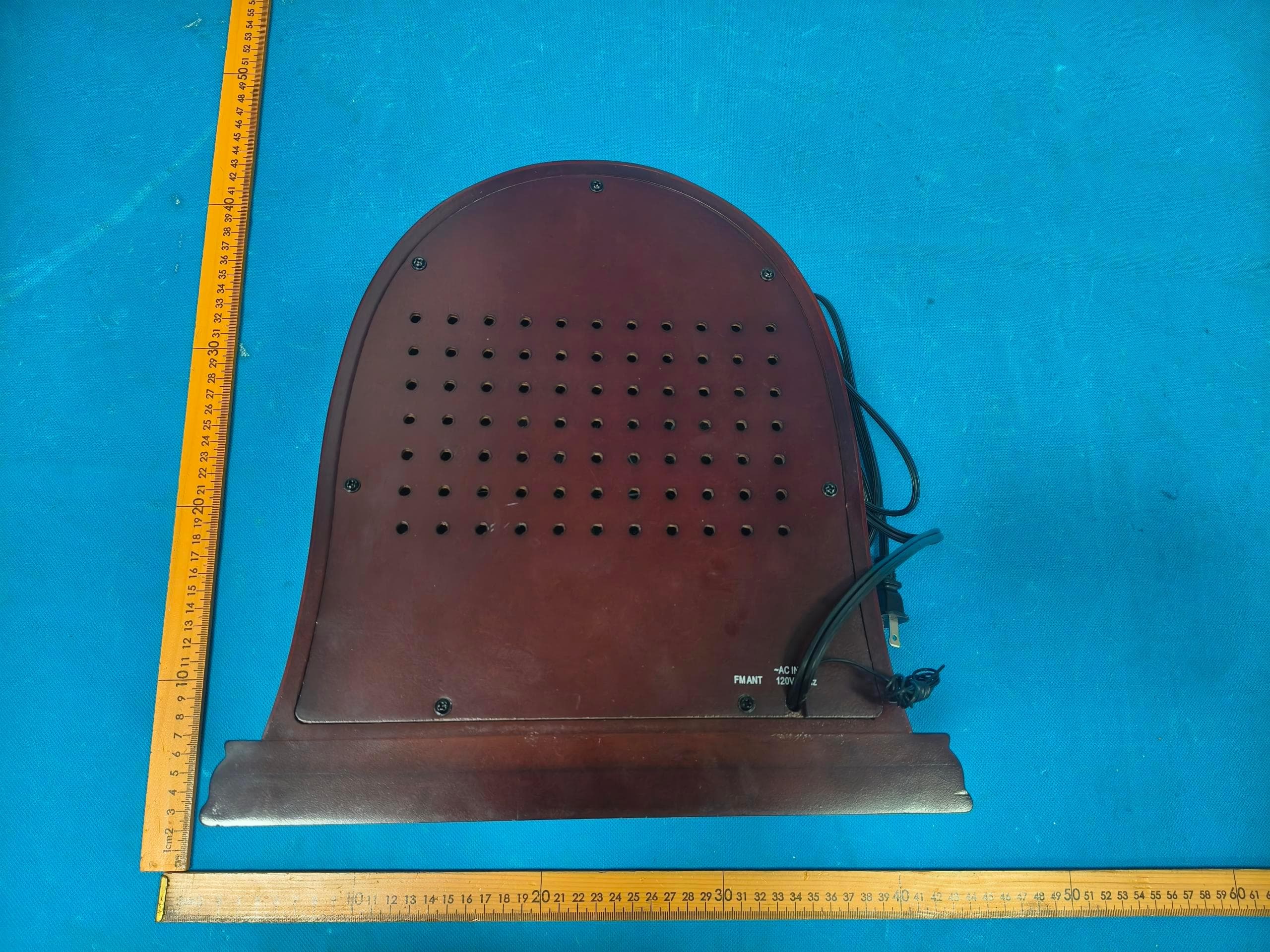
Page 1 of 4 Appendix B: Photographs of EUT Product: Retro Wooden Radio Model: VR47 External Photos Page 2 of 4 Page 3 of 4 Page 4 of 4
ID Label/Location Info
LabelArtworkandLocation Model:VR47 Label: Location FCCID:2ASDTVR47
Internal Photos
Page 1 of 6 Appendix B: Photographs of EUT Product: Retro Wooden Radio Model: VR47 Internal Photos Page 2 of 6 Page 3 of 6 Antenna Page 4 of 6 Page 5 of 6 Page 6 of 6
RF Exposure Info
Maximum Permissible Exposure Applicable Standard According to §1.1307(b), systems operating under the provisions of this section shall be operated in a manner that ensure that the public is not exposed to radio frequency energy level in excess of the Commission’s guideline. Remark: 1) The maximum output power for antenna is 7.20dBm (5.25mW) at 2441MHz, 0dBi antenna gain(with 1.00numeric antenna gain.) 2) For mobile or fixed location transmitters, no SAR consideration applied. The minimum separation generally be used is at least 20cm, even if the calculation indicate that the MPE distance would be lesser. Maximum Permissible Exposure output power= 5.25mW Numeric Antenna gain= 1.00 Substituting the MPE safe distance using d=20cm into above equation. Yields: S=0.000199*P*G Where P=Power in mW G=Numeric antenna gain S=Power density in mW/cm 2 Power density= 0.001045mW/cm 2 (For mobile or fixed location transmitters, the maximum power density is 1.0 mW/cm 2 even if the calculation indicates that the power density would be larger.)
Test Report
Hotline: 400-6611-140 Tel: 86-755-27673339 Fax: 86-755-27673332 http://www.tct-lab.com TEST REPORT FCC ID: 2ASDTVR47 Product: Retro Wooden Radio Model No.: VR47 Additional Model No.: N/A Trade Mark: Clearclick Report No.: TCT210204E015 Issued Date: Feb. 23, 2021 Issued for: ClearClick Software LLC 3006 Teak Place, Fullerton, CA 92835, United States Issued By: Shenzhen Tongce Testing Lab. 1B/F., Building 1, Yibaolai Industrial Park, Qiaotou, Fuyong, Baoan District, Shenzhen, Guangdong, China TEL: +86-755-27673339 FAX: +86-755-27673332 Note: This report shall not be reproduced except in full, without the written approval of Shenzhen Tongce Testing Lab. This document may be altered or revised by Shenzhen Tongce Testing Lab. personnel only, and shall be noted in the revision section of the document. The test results in the report only apply to the tested sample. Report No.: TCT210204E015 Page 2 of 68 Hotline: 400-6611-140 Tel: 86-755-27673339 Fax: 86-755-27673332 http://www.tct-lab.com TABLE OF CONTENTS 1. Test Certification ..................................................................................... 3 2. Test Result Summary .............................................................................. 4 3. EUT Description ....................................................................................... 5 4. General Information ................................................................................. 6 4.1. Test environment and mode ................................................................................. 6 4.2. Description of Support Units ................................................................................ 6 5. Facilities and Accreditations .................................................................. 7 5.1. Facilities ................................................................................................................. 7 5.2. Location ................................................................................................................. 7 5.3. Measurement Uncertainty ..................................................................................... 7 6. Test Results and Measurement Data ..................................................... 8 6.1. Antenna requirement ............................................................................................ 8 6.2. Conducted Emission ............................................................................................. 9 6.3. Conducted Output Power ................................................................................... 13 6.4. 20dB Occupy Bandwidth .................................................................................... 18 6.5. Carrier Frequencies Separation ......................................................................... 23 6.6. Hopping Channel Number .................................................................................. 28 6.7. Dwell Time ............................................................................................................ 31 6.8. Pseudorandom Frequency Hopping Sequence ................................................ 36 6.9. Conducted Band Edge Measurement ................................................................ 37 6.10.Conducted Spurious Emission Measurement .................................................. 41 6.11.Radiated Spurious Emission Measurement ..................................................... 45 Appendix A: Photographs of Test Setup Appendix B: Photographs of EUT Report No.: TCT210204E015 Page 3 of 68 Hotline: 400-6611-140 Tel: 86-755-27673339 Fax: 86-755-27673332 http://www.tct-lab.com 1. Test Certification Product: Retro Wooden Radio Model No.: VR47 Additional Model: N/A Trade Mark: Clearclick Applicant: ClearClick Software LLC Address: 3006 Teak Place, Fullerton, CA 92835, United States Manufacturer: Timsen Development Limited Address: 5F, 447# Tianhebei Road, Guangzhou, China Date of Test: Feb. 05, 2021 – Feb. 22, 2021 Applicable Standards: FCC CFR Title 47 Part 15 Subpart C Section 15.247 FCC KDB 558074 D01 15.247 Meas Guidance v05r02 ANSI C63.10:2013 The above equipment has been tested by Shenzhen Tongce Testing Lab. and found compliance with the requirements set forth in the technical standards mentioned above. The results of testing in this report apply only to the product/system, which was tested. Other similar equipment will not necessarily produce the same results due to production tolerance and measurement uncertainties. Tested By: Date: Feb. 22, 2021 Kevin Huang Reviewed By: Date: Feb. 23, 2021 Beryl Zhao Approved By: Date: Feb. 23, 2021 Tomsin Report No.: TCT210204E015 Page 4 of 68 Hotline: 400-6611-140 Tel: 86-755-27673339 Fax: 86-755-27673332 http://www.tct-lab.com 2. Test Result Summary Requirement CFR 47 Section Result Antenna Requirement §15.203/§15.247 (c) PASS AC Power Line Conducted Emission §15.207 PASS Conducted Peak Output Power §15.247 (b)(1) PASS 20dB Occupied Bandwidth §15.247 (a)(1) PASS Carrier Frequencies Separation §15.247 (a)(1) PASS Hopping Channel Number §15.247 (a)(1) PASS Dwell Time §15.247 (a)(1) PASS Radiated Emission §15.205/§15.209 PASS Band Edge §15.247(d) PASS Note: 1. PASS: Test item meets the requirement. 2. Fail: Test item does not meet the requirement. 3. N/A: Test case does not apply to the test object. 4. The test result judgment is decided by the limit of test standard. Report No.: TCT210204E015 Page 5 of 68 Hotline: 400-6611-140 Tel: 86-755-27673339 Fax: 86-755-27673332 http://www.tct-lab.com 3. EUT Description Product Name: Retro Wooden Radio Model : VR47 Additional Model: N/A Trade Mark: Clearclick Bluetooth version: V5.0 Operation Frequency: 2402MHz~2480MHz Transfer Rate: 1/2/3 Mbits/s Number of Channel: 79 Modulation Type: GFSK, π/4-DQPSK, 8DPSK Modulation Technology: FHSS Antenna Type: PCB Antenna Antenna Gain: 0dBi Power Supply: AC 120V Note: The antenna gain listed in this report is provided by applicant, and th…
Text truncated - open the document above for the full version.
Test Report
Report No.: TCT210204E015 Page 37 of 68 Hotline: 400-6611-140 Tel: 86-755-27673339 Fax: 86-755-27673332 http://www.tct-lab.com 6.9. Conducted Band Edge Measurement 6.9.1. Test Specification Test Requirement: FCC Part15 C Section 15.247 (d) Test Method: KDB 558074 D01 v05r02 Limit: In any 100 kHz bandwidth outside the intentional radiation frequency band, the radio frequency power shall be at least 20 dB below the highest level of the radiated power. In addition, radiated emissions which fall in the restricted bands must also comply with the radiated emission limits. Test Setup: Test Mode: Transmitting mode with modulation Test Procedure: 1. Set to the maximum power setting and enable the EUT transmit continuously. 2. Set RBW = 100 kHz (≥1% span=10MHz), VBW = 300 kHz (≥RBW). Band edge emissions must be at least 20 dB down from the highest emission level within the authorized band as measured with a 100kHz RBW. The attenuation shall be 30 dB instead of 20 dB when RMS conducted output power procedure is used. 3. Enable hopping function of the EUT and then repeat step 2 and 3. 4. Measure and record the results in the test report. Test Result: PASS 6.9.2. Test Instruments Equipment Manufacturer Model Serial Number Calibration Due Spectrum Analyzer Agilent N9020A MY49100619 Sep. 11, 2021 RF Cable (9KHz-26.5GHz) TCT RE-06 N/A Sep. 11, 2021 Antenna Connector TCT RFC-01 N/A Sep. 11, 2021 Note: The calibration interval of the above test instruments is 12 months and the calibrations are traceable to international system unit (SI). Report No.: TCT210204E015 Page 38 of 68 Hotline: 400-6611-140 Tel: 86-755-27673339 Fax: 86-755-27673332 http://www.tct-lab.com 6.9.3. Test Data GFSK Modulation Test channel: Lowest channel No-hopping mode Hopping mode Test channel: Highest channel No-hopping mode Hopping mode Report No.: TCT210204E015 Page 39 of 68 Hotline: 400-6611-140 Tel: 86-755-27673339 Fax: 86-755-27673332 http://www.tct-lab.com Pi/4DQPSK Modulation Test channel: Lowest channel No-hopping mode Hopping mode Test channel: Highest channel No-hopping mode Hopping mode Report No.: TCT210204E015 Page 40 of 68 Hotline: 400-6611-140 Tel: 86-755-27673339 Fax: 86-755-27673332 http://www.tct-lab.com 8DPSK Modulation Test channel: Lowest channel No-hopping mode Hopping mode Test channel: Highest channel No-hopping mode Hopping mode Report No.: TCT210204E015 Page 41 of 68 Hotline: 400-6611-140 Tel: 86-755-27673339 Fax: 86-755-27673332 http://www.tct-lab.com 6.10. Conducted Spurious Emission Measurement 6.10.1. Test Specification Test Requirement: FCC Part15 C Section 15.247 (d) Test Method: KDB 558074 D01 v05r02 Limit: In any 100 kHz bandwidth outside the intentional radiation frequency band, the radio frequency power shall be at least 20 dB below the highest level of the radiated power. In addition, radiated emissions which fall in the restricted bands must also comply with the radiated emission limits. Test Setup: Test Mode: Transmitting mode with modulation Test Procedure: 1. The RF output of EUT was connected to the spectrum analyzer by RF cable and attenuator. The path loss was compensated to the results for each measurement. 2. Set to the maximum power setting and enable the EUT transmit continuously. 3. Set RBW = 100 kHz, VBW = 300kHz, scan up through 10th harmonic. All harmonics / spurs must be at least 20 dB down from the highest emission level within the authorized band as measured with a 100 kHz RBW. 4. Measure and record the results in the test report. 5. The RF fundamental frequency should be excluded against the limit line in the operating frequency band. Test Result: PASS 6.10.2. Test Instruments Equipment Manufacturer Model Serial Number Calibration Due Spectrum Analyzer Agilent N9020A MY49100619 Sep. 11, 2021 Spectrum Analyzer ROHDE&SCH WARZ FSQ40 200061 Sep. 11, 2021 RF Cable (9KHz-26.5GHz) TCT RE-06 N/A Sep. 11, 2021 Antenna Connector TCT RFC-01 N/A Sep. 11, 2021 Note: The calibration interval of the above test instruments is 12 months and the calibrations are traceable to international system unit (SI). Report No.: TCT210204E015 Page 42 of 68 Hotline: 400-6611-140 Tel: 86-755-27673339 Fax: 86-755-27673332 http://www.tct-lab.com 6.10.3. Test Data GFSK mode Lowest Channel Middle Channel Highest Channel Report No.: TCT210204E015 Page 43 of 68 Hotline: 400-6611-140 Tel: 86-755-27673339 Fax: 86-755-27673332 http://www.tct-lab.com Pi/4DQPSK mode Lowest Channel Middle Channel Highest Channel Report No.: TCT210204E015 Page 44 of 68 Hotline: 400-6611-140 Tel: 86-755-27673339 Fax: 86-755-27673332 http://www.tct-lab.com 8DPSK mode Lowest Channel Middle Channel Highest Channel Report No.: TCT210204E015 Page 45 of 68 Hotline: 400-6611-140 Tel: 86-755-27673339 Fax: 86-755-27673332 http://www.tct-lab.com 6.11. Radiated Spurious Emission Measurement 6.11.1. Test Specification Test Requirement: FCC Part15 C Section 15.209 Test Method: ANSI C63.10:2013 Frequency Range: 9 kHz to 25 GHz Measurement Distance: 3 m Antenna Polarization: Horizontal & Vertical Receiver Setup: Frequency Detector RBW VBW Remark 9kHz- 150kHz Quasi-peak 200Hz 1kHz Quasi-peak Value 150kHz- 30MHz Quasi-peak 9kHz 30kHz Quasi-peak Value 30MHz-1GHz Quasi-peak 120KHz 300KHz Quasi-peak Value Above 1GHz Peak 1MHz 3MHz Peak Value Peak 1MHz 10Hz Average Value Limit: Frequency Field Strength (microvolts/meter) Measurement Distance (meters) 0.009-0.490 2400/F(KHz) 300 0.490-1.705 24000/F(KHz) 30 1.705-30 30 30 30-88 100 3 88-216 150 3 216-960 200 3 Above 960 500 3 Frequency Field Strength (microvolts/meter) Measurement Distance (meters) Detector Above 1GHz 500 3 Average 5000 3 Peak Test setup: For radiated emissions below 30MHz 30MHz to 1GHz Report No.: TCT210204E015 Page 46 of 68 Hotline: 400-6611-140 Tel: 86-755-27673339 Fax: 86-755-27673332 http://www.tct-lab.com Above 1GHz Test Mode: Transmitting mode with modulation Test Procedure: 1. The testing follows the guidelines in Spurious Radiated Emissions of ANSI C63.10:2013 Measurement Guidelines. 2.…
Text truncated - open the document above for the full version.
Test Setup Photos
Page 1 of 2 Appendix A: Photographs of Test Setup Product: Retro Wooden Radio Model: VR47 Radiated Emission Page 2 of 2 Conducted Emission
Contact Information
Applicant
Keith Gilbert
Technical Contact
Test Firm
SHENZHEN TONGCE TESTING LABBeryl Zhao
[email protected]+8675527208735
Technical Specifications
| # | Rule Parts | Frequency Range | Power Output |
|---|---|---|---|
| 1 | 15C | 2.40 GHz - 2.48 GHz | 5.20 mW |
Other Applications from ClearClick Software LLC
2ASDT-VR25
Jul 20, 2026AM/FM Vintage-Style Radio
Equipment Class
DSS - Part 15 Spread Spectrum Transmitter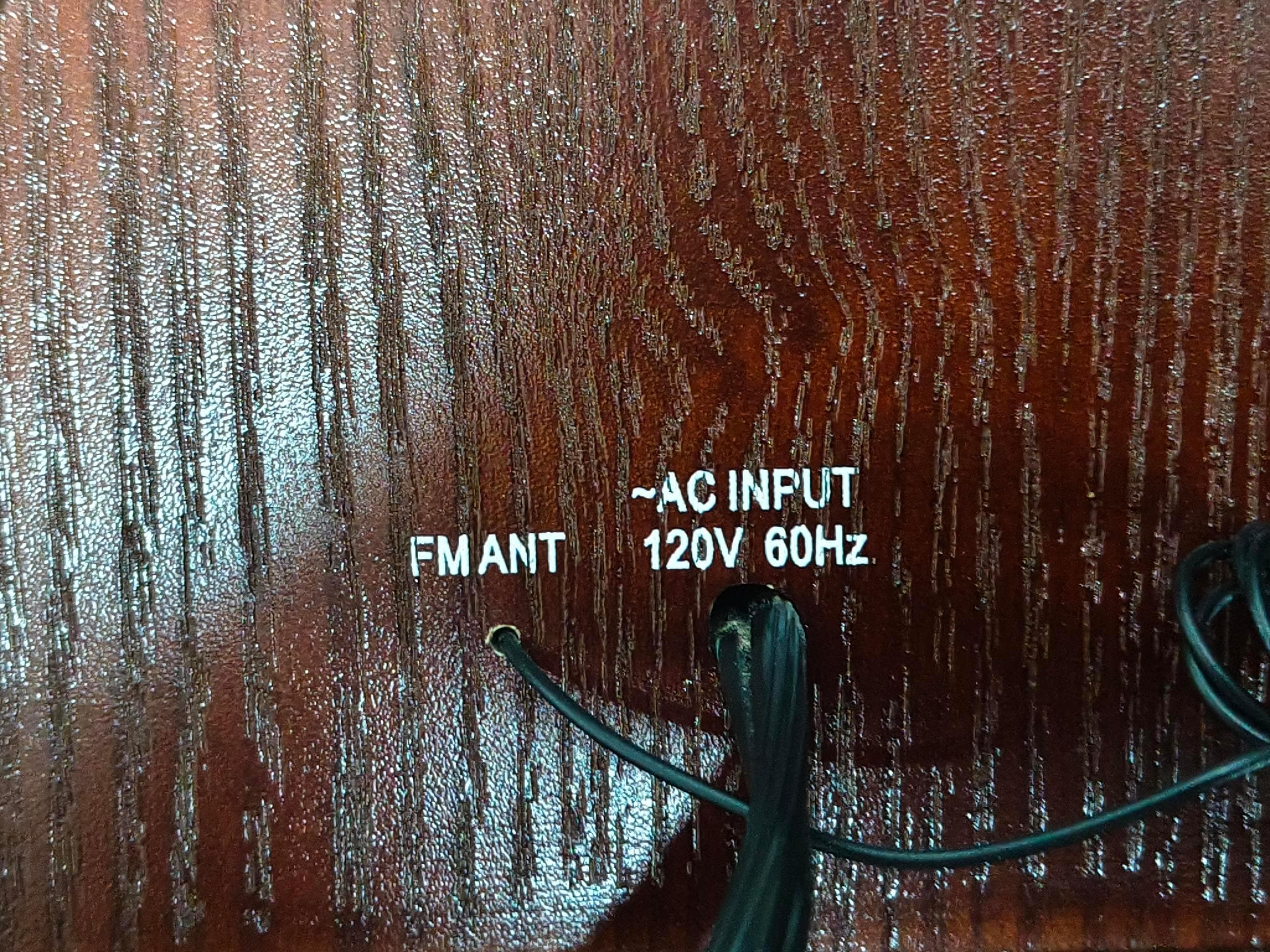
2ASDT-VT35
Jul 20, 2026All-In-One Vintage-Style Turntable
Equipment Class
DSS - Part 15 Spread Spectrum Transmitter
2ASDT-VT34
Jul 20, 2026All-In-One Vintage-Style Turntable
Equipment Class
DSS - Part 15 Spread Spectrum Transmitter
2ASDT-VT36
Jul 20, 2026All-In-One Vintage-Style Turntable
Equipment Class
DSS - Part 15 Spread Spectrum Transmitter
2ASDT-TT25
Aug 17, 2024All-In-One Vintage Style Turntable
Equipment Class
DSS - Part 15 Spread Spectrum Transmitter