2ASEQDERXXXBF7ODIN rail-mounted smart energy saver
ENKOA System, S.L.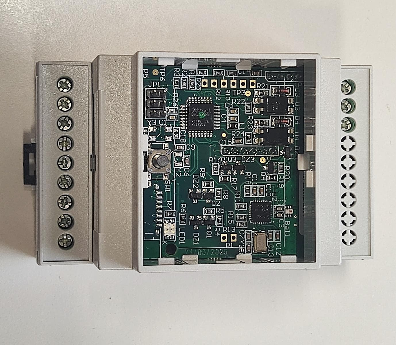
Click to zoom
Application Details
- Equipment Class
- DTS - Digital Transmission System
- Date of Grant
- Feb 19, 2026
- Application Purpose
- Original Equipment
- Equipment Note
- DIN rail-mounted smart energy saver
- Frequency Range
- 2405.00000000 - 2480.00000000
- Company
- ENKOA System, S.L.
- Country
- Spain
Documents & Files
Document Text
Text extracted from the exhibit documents filed with the FCC. Open a document above to read the original.
Users Manual
Public Instructions Manual "DIN RAIL" energy energy saver v1.3 V1.0 DATE: 19/02/2026 BY: ENKOA SYSTEM 2 Instructions manual "DIN RAIL" energy saver Public Read these instructions carefully before installing and using the iSWITCH energy saver, and keep them safe to resolve any questions. GENERAL WARNINGS AND INSTRUCTIONS FOR USE These rules must be followed to ensure correct operation of our product in your system: 1. The acquired product must be installed and used in accordance with the technical operation conditions described in the relevant guide. 2. The customer is responsible for proper use of the application. 3. Once the material is received, inspect the packaging and the material for any sign of deterioration. Also check that the delivery is complete (accessories, documentation, etc.). 4. The material must not be used if the packaging has been damaged during transport, or there is a chance that it is damaged or has a fault. Contact us if this is the case. 5. Our products must be installed and handled by authorised personnel. In particular, electrical connections must only be carried out by qualified specialists. 6. Do not attempt to repair any material after a failure or damage and start it again. It is essential that you contact us in such cases. 7. No liability will be accepted for damage caused as a result of misuse. 8. Make sure the trim cover is closed before using the unit. 9. This device is not suitable for outdoor use; it must be used indoors. 10. Do not remove any cover from the device; you could be exposed to dangerous voltage. Do not expose this unit to rain, moisture, extreme temperatures, dust or any kind of splashing or dripping. All warranties will be void if the system has been used improperly or if you have opened it, altered it, or repaired it yourself. The distributor will not accept any responsibility if the product is misused or the product has been used for a purpose other than that specified. The distributor will not accept any responsibility for additional damages other than those legally covered by the product liability. 3 Instructions manual "DIN RAIL" energy saver Public Ref. DERTxxBF7x Ref. DERXxxBF7x 4 Instructions manual "DIN RAIL" energy saver Public Contents 1. INTRODUCTION ................................................................................................................ 5 1.1 Short description ........................................................................................................... 5 1.2 Items included ............................................................................................................... 5 2. INSTALLATION .................................................................................................................. 6 2.1 Safety information in the system .................................................................................. 6 2.2 Technical specifications ................................................................................................ 7 2.3. Installation process ...................................................................................................... 8 2.3.1 Mechanical assembly ............................................................................................. 8 2.3.2 Electrical assembly ................................................................................................ 9 3. OPERATION .................................................................................................................... 11 3.1 Operation with energy savers without RFID (DERXxxBF7x) .................................... 11 3.1.1 Start-up DERXxxBF7x (Offline Mode) ................................................................ 12 3.2 Operation with RFID energy savers (DERTxxBF7x) ................................................. 14 3.2.1 Start-up DERTxxBF7x (Offline Mode) ................................................................. 15 3.3 Operation with energy savers in online mode ............................................................ 16 3.3.1 Initialising energy savers in online mode ............................................................. 16 3.4 Special energy saver cards ........................................................................................ 17 4. MAINTENANCE AND CLEANING ................................................................................... 18 5. TIPS FOR ENVIRONMENTAL PROTECTION ................................................................ 18 6. REGULATORY INFORMATION.........................................................................19 5 Instructions manual "DIN RAIL" energy saver Public 1. INTRODUCTION 1.1 Short description The iSWITCH energy saver is an electronic device to control and manage electrical energy in residential and hotel environments. It allows the power in a room to be turned on after receiving information from sensors installed in it. The unit is powered directly by the electricity supply in accordance with its characteristics and connections guide. 1.2 Items included A wiring and start-up guide will be included in each energy saver box. 6 Instructions manual "DIN RAIL" energy saver Public 2. INSTALLATION 2.1 Safety information in the system These instructions must be carefully observed before installing and starting up the iSWITCH energy saver. A connections diagram is included. The installer of the system shall be liable for any incorrect connections, in which case the warranty shall be voided. If in doubt, check with your nearest distributor. Before installing the unit, the installation instructions must be read in order to avoid any mistakes. 1. Our products must be installed and handled by authorised personnel. In particular, electrical connections must only be carried out by qualified specialists. 2. Use your unit only with the type of power shown on the marking label. Check with your utility company if you are unsure of the type of power in your system. 3. Disconnect t…
Text truncated - open the document above for the full version.
Attestation Statements
ENKOA Attention: Application Examiner Re: Certification designating a U.S. agent for service of process pursuant to section 2.911(d)(7) of the FCC To whom it may concern, This letter is to confirm both [ASSA ABLOY Global Solutions] ("Agent") and [ENKOA SYSTEM, S.L.] ("Applicant"') acknowledge consent to obligations of each party pursuant to 47 CFR part §2.911(d)(7) of the FCC rules in regard to the agent for service of process. 1 [Juan Cruz Iriondo Arrizabalaga] HEREBY CERTIFY THAT I am authorized to make the representations above on behalf of the Applicant. I further acknowledge the requirement to maintain an agent extends for no less than one year after the termination of all marketing and importation or the conclusion of and commission-related proceeding involving the equipment and agree to immediately notify the FCC and Intertck if there is any change in the status identified above. Applicant Company Name Contact Name Address Te l e p h o n e N o Email FCC ID Applicant FRN : ENKOA SYSTEM, S.L. : JUAN CRUZ IRIONDO ARRIZABALAGA : POLIGONO ERRAMONE 45, 20850 MENDARO SPAIN : +34 943707000 : [email protected] : 2ASEODERXXXBF70 : 0028180651 Signature: Date: October 6, 2025 I [insert name of agent representative] HEREBY CERTIFY THAT I am authorized to make the representations above on behalf of the Agent. 1 consent to the obligation to accept service of process on behalf of the applicant in regard to the FCC ID designated above. Agent Company Name Contact Name Address Te l e p h o n e N o Email Agent FRN : ASSA ABLOY Global Solutions : Michael J Scott : 2925 E. Plano Plano, TX 75074 United States : (810) 278-7474 [email protected] 0033780 Signature: Date: October 15, 2025 Form: RFT-AMER-TCB-OP-|90 Date: 1/25/2023 Revision: 1 Page l of 1
External Photos
Internal Internal Internal Internal
ID Label/Location Info
Internal
Internal Photos
Internal 1. Top Side Assembly View Internal 2. Side View – Fully Assembled Internal 3.Bottom View – Fully Assembled Internal 4.- Top PCB – Top View Internal Internal 5.- Top PCB – Bottom View Internal 6.- Bottom PCB – TOP View Internal 7.- Bottom PCB – bottom View
RF Exposure Info
40 51 st Way NE Suite 100 Fridley MN, 55421 www.intertek.com Enkoa System, SL RF Exposure Exhibit SCOPE OF WORK iSWITCH non card DIN rail mounted- WIRELESS energy saver REPORT NUMBER 106347494MIN-007 ISSUE DATE October 31, 2025 40 51 st Way NE Suite 100 Fridley MN, 55421 www.intertek.com EMC Report No: 106347494MIN-007 Page 2 of 8 RF Exposure Exhibit Report Number: 106347494MIN-007 Project Number: G106347494 Testing performed on the DERXXXBF7O to 47 CFR 2.1093:2025 & RSS-102 Issue 6 Updated 2023 For Enkoa System, SL Test Performed by: Test Authorized by: Intertek Testing Services NA, Inc. 40 51st Way NE, Suite 100 Fridley, MN 55421 USA Enkoa System, SL Polígono Erramone 45 20850 Mendaro (Guipúzcoa) Spain Prepared by: Jayden Alstad, EMC Project Engineer Reviewed by: Date: October 31, 2025 Uri Spector, Sr. EMC Staff Engineer This report is for the exclusive use of Intertek's Client and is provided pursuant to the agreement between Intertek and its Client. Intertek's responsibility and liability are limited to the terms and conditions of the agreement. Intertek assumes no liability to any party, other than to the Client in accordance with the agreement, for any loss, expense or damage occasioned by the use of this report. Only the Client is authorized to copy or distribute this report and then only in its entirety. Any use of the Intertek name or one of its marks for the sale or advertisement of the tested material, product or service must first be approved in writing by Intertek. The observations and test results in this report are relevant only to the sample tested. This report by itself does not imply that the material, product, or service is or has ever been under an Intertek certification program. This report must not be used to claim product endorsement by A2LA, NIST nor any other agency of the U.S. Government. 40 51 st Way NE Suite 100 Fridley MN, 55421 www.intertek.com EMC Report No: 106347494MIN-007 Page 3 of 8 TABLE OF CONTENTS 1.0 EUT Information ................................................................................................................................... 4 2.0 RF Exposure Summary ...................................................................................................................... 5 3.0 RF Exposure Limits ............................................................................................................................. 5 4.0 RF Exposure Calculations .................................................................................................................. 7 5.0 Revision History ................................................................................................................................... 8 40 51 st Way NE Suite 100 Fridley MN, 55421 www.intertek.com EMC Report No: 106347494MIN-007 Page 4 of 8 1.0 EUT Information Equipment Under Test: DERXXXBF7O Type of EUT: iSWITCH non card DIN rail mounted- WIRELESS energy saver Company: Enkoa System, SL Customer: Antonio Cid Address: Enkoa System, SL Polígono Erramone 45 20850 Mendaro (Guipúzcoa) Spain Phone: (943) 757-7030 e-mail: [email protected] Applicable Regulation: FCC 47CFR 2.1093:2025 ISED RSS-102 Issue 6 Updated 2023 Notes: The EUT consists of one radio (2.405-2.480 GHz BLE). 40 51 st Way NE Suite 100 Fridley MN, 55421 www.intertek.com EMC Report No: 106347494MIN-007 Page 5 of 8 2.0 RF Exposure Summary TEST REFERENCE RESULT Radio Frequency Radiation Exposure Evaluation FCC 47 CFR§2.1093 Pass Radio Frequency Radiation Exposure Evaluation ISED RSS-102 Pass 3.0 RF Exposure Limits In this document, we evaluate the RF Exposure to human body due to the intentional transmission from the transmitter (EUT). The limits for Maximum Permissible Exposure (MPE) specified in FCC 1.1310 and in ISED RSS-102 are below. FCC §1.1310 Radio Frequency Radiation Exposure Limits Table 1 of §1.1310(e)(1) (shown below) sets forth limits for Maximum Permissible Exposure (MPE) to radio frequency electromagnetic fields. Table 1 – Limits for Maximum Permissible Exposure 40 51 st Way NE Suite 100 Fridley MN, 55421 www.intertek.com EMC Report No: 106347494MIN-007 Page 6 of 8 ISED RSS-102 Issue 6 Radio Frequency Radiation Exposure Limits Table 7 of RSS-102 Issue 6 (shown below) sets forth limits for MPE to radio frequency electromagnetic fields. Table 7 – RF Field Strength Limits for Devices Used by the General Public (Uncontrolled Environment) 40 51 st Way NE Suite 100 Fridley MN, 55421 www.intertek.com EMC Report No: 106347494MIN-007 Page 7 of 8 4.0 RF Exposure Calculations The maximum measured antenna conducted power, P, is -0.98 dBm (reference report 106347494MIN-003). The antenna gain, G, is +3.3 dBi (per client). The maximum EIRP = P + G. Thus, 퐸퐼푅푃= −0.98 푑퐵푚+3.3 푑퐵푖=2.38 푑퐵푚=1.7298 푚푊 The Power Density, S, in mW/cm 2 is related to EIRP in mW and Antenna Separation Distance, D, in cm by the equation: 푆= 퐸퐼푅푃 4휋퐷 2 With Antenna Safe Separation Distance of 20 cm, 푆= 1.7298 4휋∗20 2 =0.000344 푚푊/푐푚 2 =0.00344 푊/푚 2 FCC Limit for f = 2405 MHz: 1.0 푚푊/푐푚 2 0.000344푚푊푐푚 2 ⁄ <1.0 푚푊/푐푚 2 ISED Limit for f = 2405 MHz: 0.02619∗2405 0.6834 푊/푚 2 =5.355 푊/푚 2 0.00344 푊/푚 2 <5.355 푊/푚 2 Therefore, the Power Density is below the MPE. 40 51 st Way NE Suite 100 Fridley MN, 55421 www.intertek.com EMC Report No: 106347494MIN-007 Page 8 of 8 5.0 Revision History REVISION LEVEL DATE REPORT NUMBER PREPARED REVIEWED NOTES 0 10-31-2025 106347494MIN-007 JA US Original Issue 1 02-05-2026 106347494MIN-007 RL US max conducted power was updated for calculations
Test Report
Internal 20251015 DER Antenna (Inverted F) FECHA: 15/10/2025 RESPONSABLE: Alberto Peñas 2 Internal Model:DERXxXBF7O FCC ID 2ASEQDERXXXBF7O Energy saver mounted on DIN rail The iSWITCH energy saver is an electronic control device designed to optimize and manage electrical energy usage in residential and hotel environments. Its main function is to regulate the availability of electrical power within a room, enabling it only after receiving activation signals from connected sensors (e.g., door sensors, motion detectors...). The device features wireless communication based on the IEEE 802.15.4 standard at 2.4 GHz, Top View of Control Board (Altium 3D Render) 20251015 DER Antenna (Inverted F) 3 Internal The control board contains the radio system, whereas the power supply board does not have a radio system. Control Board The radio circuit is mounted on the 4-layer control board. 4 layer PCB / FR4 / 1.6mm 4 Internal TOP VIEW The antenna is an inverted F antenna routed on the same PCB. GND 2.4Ghz Inverted F Antenna Printed in circuit board Chip type SMD Balun. 2.4Ghz. 1:2 Ratio, 50/100Ω Impedance 16Mhz Crystal for transceiver 5 Internal Ground Plane The antenna design is based on the attached application note from the manufacturer Texas Instruments. swru120d Application Report 2.4-GHz Inverted F Antenna TI.pdf
Test Report
Application Report 2.4-GHz Inverted F Antenna ABSTRACT This document describes a printed-circuit board (PCB) antenna design that can be used with all 2.4-GHz transceivers and transmitters from Texas Instruments ™ . The maximum gain when used on the reference board is measured to be +3.3 dBi, and the overall size requirements for this antenna are 25.7 × 7.5 mm (not including ground plane). Table of Contents 1 Description of the antenna Design........................................................................................................................................2 2 Measurement Results.............................................................................................................................................................3 2.1 Radiation Pattern...............................................................................................................................................................3 2.2 Reflection.........................................................................................................................................................................10 2.3 Bandwidth.........................................................................................................................................................................11 3 Summary................................................................................................................................................................................11 4 References.............................................................................................................................................................................11 5 Revision History...................................................................................................................................................................12 Trademarks Texas Instruments ™ is a trademark of Texas Instruments. All trademarks are the property of their respective owners. www.ti.comTable of Contents SWRU120D – APRIL 2007 – REVISED JANUARY 2019 Submit Document Feedback 2.4-GHz Inverted F Antenna1 Copyright © 2021 Texas Instruments Incorporated 1 Description of the antenna Design It is important to make an exact copy of the antenna dimensions to obtain optimum performance. The easiest approach to implement the antenna in a PCB CAD tool is to import the antenna layout from a gerber file or a DXF file. Such files are included in CC2430DB reference design [1]. The gerber file is called Inverted_F_Antenna.spl and the DXF file is called Inverted_F_Antenna.dxf. If the antenna is implemented on a PCB that is wider than the antenna, avoid placing components or having a ground plane close to the end points of the antenna. If the CAD tool being used does not support importing gerber or DXF files, see Figure 1-1 and Table 1-1. The antenna impedance is tuned to 50 ohm on the reference board. The impedance will however be affected by different size and shape of the ground plane, objects in the antenna nearfield such as mechanical assemblies (housing, batteries, etc.), PCB thickness, PCB material and so on. It is therefore recommended to add a pi-network close to the antenna feedpoint for impedance matching. The results presented in this document are based on an antenna implemented on a PCB with a 1-mm thickness using standard FR-4 material. Figure 1-1. IFA Dimensions Table 1-1. IFA Dimensions H15.70 mmW20.46 mm H20.74 mmL125.58 mm H31.29 mmL216.40 mm H42.21 mmL32.18 mm H50.66 mmL44.80 mm H61.21 mmL51.00 mm H70.80 mmL61.00 mm H81.80 mmL73.20 mm H90.61 mmL80.45 mm W11.21 mm Description of the antenna Designwww.ti.com 22.4-GHz Inverted F AntennaSWRU120D – APRIL 2007 – REVISED JANUARY 2019 Submit Document Feedback Copyright © 2021 Texas Instruments Incorporated 2 Measurement Results All of the results presented in this section are based on measurements performed with the CC2430DB [1] evaluation board. 2.1 Radiation Pattern Figure 2-1 shows how to relate all of the radiation patterns to the orientation of the antenna. The radiation patterns were measured with the CC2430 device programmed to 0-dBm output power. Figure 2-1. Relating Antenna to Radiation Patterns www.ti.comMeasurement Results SWRU120D – APRIL 2007 – REVISED JANUARY 2019 Submit Document Feedback 2.4-GHz Inverted F Antenna3 Copyright © 2021 Texas Instruments Incorporated Figure 2-2 shows the XY plane vertical polarization. Figure 2-2. XY Plane–Vertical Polarization Measurement Resultswww.ti.com 42.4-GHz Inverted F AntennaSWRU120D – APRIL 2007 – REVISED JANUARY 2019 Submit Document Feedback Copyright © 2021 Texas Instruments Incorporated Figure 2-3 shows the XY plane horizontal polarization. Figure 2-3. XY Plane–Horizontal Polarization www.ti.comMeasurement Results SWRU120D – APRIL 2007 – REVISED JANUARY 2019 Submit Document Feedback 2.4-GHz Inverted F Antenna5 Copyright © 2021 Texas Instruments Incorporated Figure 2-4 shows the XZ plane vertical polarization. Figure 2-4. XZ Plane–Vertical Polarization Measurement Resultswww.ti.com 62.4-GHz Inverted F AntennaSWRU120D – APRIL 2007 – REVISED JANUARY 2019 Submit Document Feedback Copyright © 2021 Texas Instruments Incorporated Figure 2-5 shows the XZ plane horizontal polarization. Figure 2-5. XZ Plane–Horizontal Polarization www.ti.comMeasurement Results SWRU120D – APRIL 2007 – REVISED JANUARY 2019 Submit Document Feedback 2.4-GHz Inverted F Antenna7 Copyright © 2021 Texas Instruments Incorporated Figure 2-6 shows the YZ plane vertical polarization. Figure 2-6. YZ Plane–Vertical Polarization Measurement Resultswww.ti.com 82.4-GHz Inverted F AntennaSWRU120D – APRIL 2007 – REVISED JANUARY 2019 Submit Document Feedback Copyright © 2021 Texas Instruments Incorporated Figure 2-7 shows the YZ plane horizontal polarization. Figure 2-7. YZ Plane–Horizontal Polarization www.ti.comMeasurement Results SWRU120D – APRIL 2007 – REVISED JANUARY 2019 Submit Document Feedback 2.4-GHz Inverted F Antenna9 Copyright © 202…
Text truncated - open the document above for the full version.
Test Report
TEST REPORT Report Number: 106347494MIN-003 Project Number: G106347494 Testing performed on the DERXXXBF7O FCC ID: 2ASEQDERXXXBF7O IC: 24733-DERXXXBF7O to 47 CFR, Part 15. 247:2025 RSS- 247, Issue 4, 2025 RSS-Gen, Issue 5, Amendment 2:2021 For Enkoa System, SL Test Performed by: Test Authorized by: Intertek Testing Services NA, Inc. 40 51st Way NE, Suite 100 Fridley, MN 55421 USA Enkoa System, SL Polígono Erramone 45 20850 Mendaro (Guipúzcoa) Spain Prepared by: Peter Kutkiewicz, Project EMC Engineer Reviewed by: Date of issue: 2025-12-10 Uri Spector, Sr. EMC Staff Engineer This report is for the exclusive use of Intertek's Client and is provided pursuant to the agreement between Intertek and its Client. Intertek's responsibility and liability are limited to the terms and conditions of the agreement. Intertek assumes no liability to any party, other than to the Client in accordance with the agreement, for any loss, expense or damage occasioned by the use of this report. Only the Client is authorized to permit copying or distribution of this report and then only in its entirety. Any use of the Intertek name or one of its marks for the sale or advertisement of the tested material, product or service must first be approved in writing by Intertek. The observations and test results in this report are relevant only to the sample tested. This report by itself does not imply that the material, product, or service is or has ever been under an Intertek certification program. EMC Report No: 106347494MIN-003, FCC ID: 2ASEQDERXXXBF7O, IC: 24733-DERXXXBF7O Page 2 of 58 TABLE OF CONTENTS 1.0 GENERAL DESCRIPTION.......................................................................................................... 3 1.1 Product Description; Test Facility ....................................................................................... 4 1.2 EUT Configuration .............................................................................................................. 5 1.3 EUT Block Diagrams: ......................................................................................................... 5 1.4 Environmental conditions .................................................................................................... 6 1.5 Measurement uncertainty ................................................................................................... 6 1.6 Field Strength Calculation................................................................................................... 7 2.0 TEST SUMMARY.......................................................................................................................... 8 3.0 TEST CONDITIONS AND RESULTS ........................................................................................ 9 3.1 6dB Emission bandwidth (EBW) of the digital modulation ................................................. 9 3.1.1 Occupied Bandwidth (OBW) (99%) ............................................................................... 13 3.2 Maximum peak output power ........................................................................................... 17 3.3 Power spectral density ...................................................................................................... 22 3.4 Antenna conducted spurious emissions ........................................................................... 26 3.5 Radiated spurious emissions ............................................................................................ 35 3.6 Transmitter power line conducted emissions ................................................................... 54 4.0 TEST EQUIPMENT .................................................................................................................... 57 5.0 REVISION HISTORY.................................................................................................................. 58 EMC Report No: 106347494MIN-003, FCC ID: 2ASEQDERXXXBF7O, IC: 24733-DERXXXBF7O Page 3 of 58 1.0 GENERAL DESCRIPTION Model: DERXXXBF7O Type of EUT: iSWITCH non card DIN rail mounted- WIRELESS energy saver Intertek Sample ID: MIN2510061029-002 (Configured for antenna port measurements) MIN2510061029-004 (Configured for radiated measurements) FCC ID: 2ASEQDERXXXBF7O IC: 24733-DERXXXBF7O Related Submittal(s) Grants: None Company: Enkoa System, SL Customer: Antonio Cid Address: Polígono Erramone 45 20850 Mendaro (Guipúzcoa) Spain Phone: 943-757-7030 e-mail: [email protected] Test Standards: 47 CFR, Part 15 Subpart C:2025, §15.247 RSS–247, Issue 4, 2025 RSS-Gen, Issue 5, 2021, Amendment 2 Other Type of radio: Stand-alone Module Hybrid Date Sample Submitted: 2025-10-06 Test Work Started: 2025-10-06 Test Work Completed: 2025-12-03 Test Sample Conditions: Damaged Poor (Usable) Good EMC Report No: 106347494MIN-003, FCC ID: 2ASEQDERXXXBF7O, IC: 24733-DERXXXBF7O Page 4 of 58 1.1 Product Description; Test Facility Product Description: iSWITCH non card DIN rail mounted- WIRELESS energy saver Transmitter Type: FHSS Digital Modulation WiFi Blue Tooth Permitted Band of Operation: 2.4 GHz – 2.4835 GHz Operating Frequency Range(s): 2.405 GHz – 2.48 GHz Number of Channels: 26 Modulation: O-QPSK Antenna(s) Info: Microchip Technology AT86RF231 inverted F antenna. Antenna gain: +3.3 dBi Power settings: Internal register value set to 0x0, corresponding to an output power of TX_PWR = 3.0 dBm Antenna Installation: User Professional Factory Transmitter power configuration: Internal battery External power source 100-240VAC 230VAC 400VAC VDC Other: 0.1-0.05 Amp. 50Hz 60Hz Note: All measurements were performed while EUT was powered at 120VAC/60Hz. Special Test Arrangement: Per client, the EUT is mounted inside electrical boxes with DIN rail mounting in the vertical position. Test Facility Accreditation: A2LA (Certificate No. 1427.01) Test Methodology: Measurements performed according to the procedures in ANSI C63.10- 2020+Cor1:2023+C63.10a:2024 and FCC 558074 D01 DTS Measurement…
Text truncated - open the document above for the full version.
Test Setup Photos
Test Setup Photos
Contact Information
Applicant
Juan Cruz Iriondo Arrizabalaga(Mr.)
[email protected]Fax: +34943757030
Technical Contact
ASSA ABLOY Global SolutionsMichael Scott
2925 E Plano Parkway · Plano, Texas, 75074 · United States
Test Firm
Intertek Testing Services NA, Inc.Andrew Waytulonis
[email protected]Fax: 651 702 9132
Technical Specifications
| # | Rule Parts | Frequency Range | Power Output |
|---|---|---|---|
| 1 | 15C | 2.40 GHz - 2.48 GHz | 800.00 µW |