2ASEQSVOXIXSCeiling surface mounted motion sensor
ENKOA System, S.L.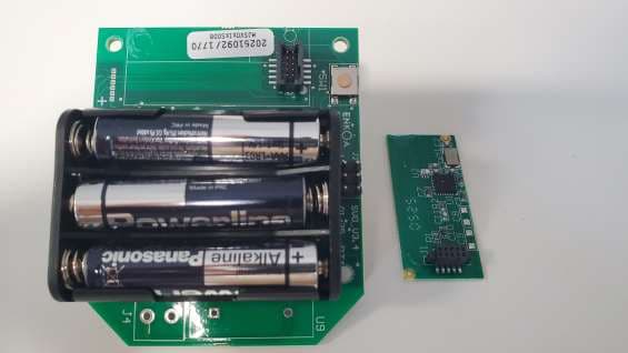
Click to zoom
Application Details
- Equipment Class
- DTS - Digital Transmission System
- Date of Grant
- Mar 13, 2026
- Application Purpose
- Original Equipment
- Equipment Note
- Ceiling surface mounted motion sensor
- Frequency Range
- 2405.00000000 - 2480.00000000
- Company
- ENKOA System, S.L.
- Country
- Spain
Documents & Files
Document Text
Text extracted from the exhibit documents filed with the FCC. Open a document above to read the original.
Users Manual
Public User’s Guide Motion Sensor DATE: 10/03/2026 RESPONSABLE: Enkoa 2 GENERAL WARNINGS AND INSTRUCTION GUIDE Read carefully the instruction given, before installing and using the motion sensor and hold it for future references. In order to ensure the correct operation of the product in your installation is necessary to carry the following safety regulations out: 1. The installation and the use of the product must be done according to the technical operating conditions explained below. 2. The good use of the application is client’s responsibility. 3. After reception of the goods, check the packaging and the existing material in case there is any damage. Check as well, that the reception is complete (accessories, papers, etc). 4. If packaging is damaged during delivery or it is suspicious of being damaged or having a failure, do not put the unit on. In that case please contact us. 5. The installation and handling of our product has to be done by authorized personnel. Mainly the electrical connections must be done only by qualified experts. 6. Do not try to repair any material after a failure or damage and put it working again. In this case it is highly important to contact us. 7. There will not be accepted any responsibility for damages caused by a wrong use. Ensure that the top and the low caps are unified and correctly screwed before starting the unit up. User’s Guide. Motion Sensor Vs4 3 AVERTISSEMENTS GÉNÉRAUX ET GUIDE D’INSTRUCTIONS Veuillez lire attentivement les instructions fournies avant d’installer et d’utiliser le détecteur de mouvement, et conservez-les pour de futures références. Afin de garantir le bon fonctionnement du produit dans votre installation, il est nécessaire de respecter les consignes de sécurité suivantes : 1. L’installation et l’utilisation du produit doivent être effectuées conformément aux conditions techniques de fonctionnement décrites ci-après. 2. La bonne utilisation de l’équipement relève de la responsabilité de l’utilisateur. 3. À la réception du matériel, vérifiez l’état de l’emballage et du contenu afin de détecter tout dommage éventuel. Vérifiez également que la livraison est complète (accessoires, documents, etc.). 4. Si l’emballage a été endommagé durant le transport, ou si vous soupçonnez un dommage ou un défaut, n’allumez pas l’appareil. Dans ce cas, veuillez nous contacter. 5. L’installation et la manipulation de ce produit doivent être réalisées par du personnel autorisé. En particulier, les connexions électriques doivent être effectuées exclusivement par des techniciens qualifiés. 6. Ne tentez pas de réparer l’appareil après un dommage ou un dysfonctionnement, ni de le remettre en service. Dans ce cas, il est impératif de nous contacter. 7. Aucune responsabilité ne sera acceptée en cas de dommages causés par une utilisation incorrecte du produit. Assurez-vous que les capuchons supérieur et inférieur sont correctement assemblés et solidement vissés avant la mise en service de l’appareil. 4 INDICE: 1. INTRODUCTION ................................................................................................... 5 1.1 Brief description ......................................................................................................... 5 1.2 Shipment content ...................................................................................................... 5 2. INSTALLATION ....................................................................................................... 6 2.1 Dimensions ....................................................................................................................... 7 2.2 Installation process .......................................................................................................... 7 3. OPERATION ............................................................................................................ 9 3.1 saving mode ..................................................................................................................... 9 3.2 Room comfort option ....................................................................................................... 9 3.3 Security Option ................................................................................................................. 9 4. MAINTENANCE AND CLEANING ......................................................................... 10 4.1 Battery replacement ...................................................................................................... 10 5. TECHNICAL DATA ................................................................................................ 11 6. TIPPS FOR PROTECTING THE ENVIRONMENT .................................................. 12 7. CONSEILS POUR PROTÉGER L’ENVIRONNEMENT .......................................... 12 8. OPERATING PRECAUTIONS ................................................................................ 13 9. REGULATORY INFORMATION ............................................................................. 14 10. INFORMATIONS RÉGLEMENTAIRES ................................................................ 16 5 1. INTRODUCTION 1.1 Brief description The MOTION SENSOR is a passiv infrated detector device that detects people movement through the room. In addition, it features a thermostat that measures room temperature and humidity. It has a wireless communication with the Iswitch energy saver and sends movement information and the room temperature to the energy saver. The energy saver enables connect or disconnect the room devices depending on the information sent by the motion sensor. The MOTION SENSOR is standalone and is operated by 3 batteries of 1.5 V LR3 AAA (non rechargeable). 1.2 Shipment content • MOTION SENSOR • Screw box (2 screws and 2 number five plugs to fix it in the ceiling. 1 side screw to close the cap.) • User’s and starting up user’s guide. 6 2. INSTALLATION The MOTION SENSOR will be always overhead mounted. The MOTION SENSOR’S install…
Text truncated - open the document above for the full version.
RF Exposure Info
40 51 st Way NE Suite 100 Fridley MN, 55421 www.intertek.com Enkoa System, SL RF Exposure Exhibit SCOPE OF WORK Ceiling surface mounted motion sensor REPORT NUMBER 106347521MIN-007 ISSUE DATE October 31, 2025 40 51 st Way NE Suite 100 Fridley MN, 55421 www.intertek.com EMC Report No: 106347521MIN-007 Page 2 of 8 RF Exposure Exhibit Report Number: 106347521MIN-007 Project Number: G106347521 Testing performed on the SVOXIXS to 47 CFR 2.1093:2025 & RSS-102 Issue 6 Updated 2023 For Enkoa System, SL Test Performed by: Test Authorized by: Intertek Testing Services NA, Inc. 40 51st Way NE, Suite 100 Fridley, MN 55421 USA Enkoa System, SL Polígono Erramone 45 20850 Mendaro (Guipúzcoa) Spain Prepared by: Jayden Alstad, EMC Project Engineer Reviewed by: Date: October 31, 2025 Uri Spector, Sr. EMC Staff Engineer This report is for the exclusive use of Intertek's Client and is provided pursuant to the agreement between Intertek and its Client. Intertek's responsibility and liability are limited to the terms and conditions of the agreement. Intertek assumes no liability to any party, other than to the Client in accordance with the agreement, for any loss, expense or damage occasioned by the use of this report. Only the Client is authorized to copy or distribute this report and then only in its entirety. Any use of the Intertek name or one of its marks for the sale or advertisement of the tested material, product or service must first be approved in writing by Intertek. The observations and test results in this report are relevant only to the sample tested. This report by itself does not imply that the material, product, or service is or has ever been under an Intertek certification program. This report must not be used to claim product endorsement by A2LA, NIST nor any other agency of the U.S. Government. 40 51 st Way NE Suite 100 Fridley MN, 55421 www.intertek.com EMC Report No: 106347521MIN-007 Page 3 of 8 TABLE OF CONTENTS 1.0 EUT Information ................................................................................................................................... 4 2.0 RF Exposure Summary ...................................................................................................................... 5 3.0 RF Exposure Limits ............................................................................................................................. 5 4.0 RF Exposure Calculations .................................................................................................................. 7 5.0 Revision History ................................................................................................................................... 8 40 51 st Way NE Suite 100 Fridley MN, 55421 www.intertek.com EMC Report No: 106347521MIN-007 Page 4 of 8 1.0 EUT Information Equipment Under Test: SVOXIXS Type of EUT: Ceiling surface mounted motion sensor Company: Enkoa System, SL Customer: Antonio Cid Address: Enkoa System, SL Polígono Erramone 45 20850 Mendaro (Guipúzcoa) Spain Phone: (943) 757-7030 e-mail: [email protected] Applicable Regulation: FCC 47CFR 2.1093:2025 ISED RSS-102 Issue 6 Updated 2023 Notes: The EUT consists of one radio (2.405-2.480 GHz BLE). 40 51 st Way NE Suite 100 Fridley MN, 55421 www.intertek.com EMC Report No: 106347521MIN-007 Page 5 of 8 2.0 RF Exposure Summary TEST REFERENCE RESULT Radio Frequency Radiation Exposure Evaluation FCC 47 CFR§2.1093 Pass Radio Frequency Radiation Exposure Evaluation ISED RSS-102 Pass 3.0 RF Exposure Limits In this document, we evaluate the RF Exposure to human body due to the intentional transmission from the transmitter (EUT). The limits for Maximum Permissible Exposure (MPE) specified in FCC 1.1310 and in ISED RSS-102 are below. FCC §1.1310 Radio Frequency Radiation Exposure Limits Table 1 of §1.1310(e)(1) (shown below) sets forth limits for Maximum Permissible Exposure (MPE) to radio frequency electromagnetic fields. Table 1 – Limits for Maximum Permissible Exposure 40 51 st Way NE Suite 100 Fridley MN, 55421 www.intertek.com EMC Report No: 106347521MIN-007 Page 6 of 8 ISED RSS-102 Issue 6 Radio Frequency Radiation Exposure Limits Table 7 of RSS-102 Issue 6 (shown below) sets forth limits for MPE to radio frequency electromagnetic fields. Table 7 – RF Field Strength Limits for Devices Used by the General Public (Uncontrolled Environment) 40 51 st Way NE Suite 100 Fridley MN, 55421 www.intertek.com EMC Report No: 106347521MIN-007 Page 7 of 8 4.0 RF Exposure Calculations The maximum measured antenna conducted power, P, is 2.24 dBm (reference report 106347521MIN-003). The antenna gain, G, is +3.3 dBi (per client). The maximum EIRP = P + G. Thus, 퐸퐼푅푃= 2.24 푑퐵푚+3.3 푑퐵푖=5.54 푑퐵푚=3.58096 푚푊 The Power Density, S, in mW/cm 2 is related to EIRP in mW and Antenna Separation Distance, D, in cm by the equation: 푆= 퐸퐼푅푃 4휋퐷 2 With Antenna Safe Separation Distance of 20 cm, 푆= 3.58096 4휋∗20 2 =0.00071241 푚푊/푐푚 2 =0.0071241 푊/푚 2 FCC Limit for f = 2405 MHz: 1.0 푚푊/푐푚 2 0.00050434푚푊푐푚 2 ⁄ <1.0 푚푊/푐푚 2 ISED Limit for f = 2405 MHz: 0.02619∗2405 0.6834 푊/푚 2 =5.355 푊/푚 2 0.0071241 푊/푚 2 <5.355 푊/푚 2 Therefore, the Power Density is below the MPE. 40 51 st Way NE Suite 100 Fridley MN, 55421 www.intertek.com EMC Report No: 106347521MIN-007 Page 8 of 8 5.0 Revision History REVISION LEVEL DATE REPORT NUMBER PREPARED REVIEWED NOTES 0 10-31-2025 106347521MIN-007 JA US Original Issue -
Test Report
Application Report 2.4-GHz Inverted F Antenna ABSTRACT This document describes a printed-circuit board (PCB) antenna design that can be used with all 2.4-GHz transceivers and transmitters from Texas Instruments ™ . The maximum gain when used on the reference board is measured to be +3.3 dBi, and the overall size requirements for this antenna are 25.7 × 7.5 mm (not including ground plane). Table of Contents 1 Description of the antenna Design........................................................................................................................................2 2 Measurement Results.............................................................................................................................................................3 2.1 Radiation Pattern...............................................................................................................................................................3 2.2 Reflection.........................................................................................................................................................................10 2.3 Bandwidth.........................................................................................................................................................................11 3 Summary................................................................................................................................................................................11 4 References.............................................................................................................................................................................11 5 Revision History...................................................................................................................................................................12 Trademarks Texas Instruments ™ is a trademark of Texas Instruments. All trademarks are the property of their respective owners. www.ti.comTable of Contents SWRU120D – APRIL 2007 – REVISED JANUARY 2019 Submit Document Feedback 2.4-GHz Inverted F Antenna1 Copyright © 2021 Texas Instruments Incorporated 1 Description of the antenna Design It is important to make an exact copy of the antenna dimensions to obtain optimum performance. The easiest approach to implement the antenna in a PCB CAD tool is to import the antenna layout from a gerber file or a DXF file. Such files are included in CC2430DB reference design [1]. The gerber file is called Inverted_F_Antenna.spl and the DXF file is called Inverted_F_Antenna.dxf. If the antenna is implemented on a PCB that is wider than the antenna, avoid placing components or having a ground plane close to the end points of the antenna. If the CAD tool being used does not support importing gerber or DXF files, see Figure 1-1 and Table 1-1. The antenna impedance is tuned to 50 ohm on the reference board. The impedance will however be affected by different size and shape of the ground plane, objects in the antenna nearfield such as mechanical assemblies (housing, batteries, etc.), PCB thickness, PCB material and so on. It is therefore recommended to add a pi-network close to the antenna feedpoint for impedance matching. The results presented in this document are based on an antenna implemented on a PCB with a 1-mm thickness using standard FR-4 material. Figure 1-1. IFA Dimensions Table 1-1. IFA Dimensions H15.70 mmW20.46 mm H20.74 mmL125.58 mm H31.29 mmL216.40 mm H42.21 mmL32.18 mm H50.66 mmL44.80 mm H61.21 mmL51.00 mm H70.80 mmL61.00 mm H81.80 mmL73.20 mm H90.61 mmL80.45 mm W11.21 mm Description of the antenna Designwww.ti.com 22.4-GHz Inverted F AntennaSWRU120D – APRIL 2007 – REVISED JANUARY 2019 Submit Document Feedback Copyright © 2021 Texas Instruments Incorporated 2 Measurement Results All of the results presented in this section are based on measurements performed with the CC2430DB [1] evaluation board. 2.1 Radiation Pattern Figure 2-1 shows how to relate all of the radiation patterns to the orientation of the antenna. The radiation patterns were measured with the CC2430 device programmed to 0-dBm output power. Figure 2-1. Relating Antenna to Radiation Patterns www.ti.comMeasurement Results SWRU120D – APRIL 2007 – REVISED JANUARY 2019 Submit Document Feedback 2.4-GHz Inverted F Antenna3 Copyright © 2021 Texas Instruments Incorporated Figure 2-2 shows the XY plane vertical polarization. Figure 2-2. XY Plane–Vertical Polarization Measurement Resultswww.ti.com 42.4-GHz Inverted F AntennaSWRU120D – APRIL 2007 – REVISED JANUARY 2019 Submit Document Feedback Copyright © 2021 Texas Instruments Incorporated Figure 2-3 shows the XY plane horizontal polarization. Figure 2-3. XY Plane–Horizontal Polarization www.ti.comMeasurement Results SWRU120D – APRIL 2007 – REVISED JANUARY 2019 Submit Document Feedback 2.4-GHz Inverted F Antenna5 Copyright © 2021 Texas Instruments Incorporated Figure 2-4 shows the XZ plane vertical polarization. Figure 2-4. XZ Plane–Vertical Polarization Measurement Resultswww.ti.com 62.4-GHz Inverted F AntennaSWRU120D – APRIL 2007 – REVISED JANUARY 2019 Submit Document Feedback Copyright © 2021 Texas Instruments Incorporated Figure 2-5 shows the XZ plane horizontal polarization. Figure 2-5. XZ Plane–Horizontal Polarization www.ti.comMeasurement Results SWRU120D – APRIL 2007 – REVISED JANUARY 2019 Submit Document Feedback 2.4-GHz Inverted F Antenna7 Copyright © 2021 Texas Instruments Incorporated Figure 2-6 shows the YZ plane vertical polarization. Figure 2-6. YZ Plane–Vertical Polarization Measurement Resultswww.ti.com 82.4-GHz Inverted F AntennaSWRU120D – APRIL 2007 – REVISED JANUARY 2019 Submit Document Feedback Copyright © 2021 Texas Instruments Incorporated Figure 2-7 shows the YZ plane horizontal polarization. Figure 2-7. YZ Plane–Horizontal Polarization www.ti.comMeasurement Results SWRU120D – APRIL 2007 – REVISED JANUARY 2019 Submit Document Feedback 2.4-GHz Inverted F Antenna9 Copyright © 202…
Text truncated - open the document above for the full version.
Test Report
Internal 20251006 SVO Antenna (Inverted F) FECHA: 06/10/2025 RESPONSABLE: Antonio Cid 2 Internal Model:SVOxIxS FCC ID 2ASEQSVOXIXS Ceiling surface mounted motion sensor The motion sensor is a passive infrared detector device that detects people movement through the room, and measures temperature and humidity. It has wireless communication (2.4GHz, IEEE802.15.4 Images taken from Altium 3D. Top and bottom: TOP VIEW BOTTOM VIEW MODBEE Radio Module. Separate PCB. Connected to the main PCB by a connector. Designed by Enkoa It is not a pre-certified module Inverted F Antenna Main PCB. No hay radio en esta placa. 20251006 SVO Antenna (Inverted F) 3 Internal MODBEE Radio Module 2 layer PCB / FR4 / 0.8mm TOP VIEW BOTTOM VIEW 2.4 GHz Transceiver for IEEE 802.15.4 Microchip AT86RF231 or AT86RF233 Connector between both PCBs 16Mhz Crystal for transceiver Chip type SMD Balun. 2.4Ghz. 1:2 Ratio, 50/100Ω Impedance 2.4Ghz Inverted F Antenna Printed in circuit board GND GND 4 Internal The antenna is an inverted F antenna routed on the same PCB. Ground Plane TOP in Red // BOT in Blue The antenna design is based on the attached application note from the manufacturer Texas Instruments. swru120d Application Report 2.4-GHz Inverted F Antenna TI.pdf
Test Report
TEST REPORT Report Number: 106347521MIN-003 Project Number: G106347521 Testing performed on the SVOXIXS FCC ID: 2ASEQSVOXIXS IC: 24733-SVOXIXS to 47 CFR, Part 15. 247:2025 RSS- 247, Issue 4, 2025 RSS-Gen, Issue 5, Amendment 2:2021 For Enkoa System, SL Test Performed by: Test Authorized by: Intertek Testing Services NA, Inc. 40 51st Way NE, Suite 100 Fridley, MN 55421 USA Enkoa System, SL Polígono Erramone 45 20850 Mendaro (Guipúzcoa) Spain Prepared by: Peter Kutkiewicz, Project EMC Engineer Reviewed by: Date of issue: 2025-12-10 Uri Spector, Sr. EMC Staff Engineer This report is for the exclusive use of Intertek's Client and is provided pursuant to the agreement between Intertek and its Client. Intertek's responsibility and liability are limited to the terms and conditions of the agreement. Intertek assumes no liability to any party, other than to the Client in accordance with the agreement, for any loss, expense or damage occasioned by the use of this report. Only the Client is authorized to permit copying or distribution of this report and then only in its entirety. Any use of the Intertek name or one of its marks for the sale or advertisement of the tested material, product or service must first be approved in writing by Intertek. The observations and test results in this report are relevant only to the sample tested. This report by itself does not imply that the material, product, or service is or has ever been under an Intertek certification program. EMC Report No: 106347521MIN-003, FCC ID: 2ASEQSVOXIXS, IC: 24733-SVOXIXS Page 2 of 55 TABLE OF CONTENTS 1.0 GENERAL DESCRIPTION.......................................................................................................... 3 1.1 Product Description; Test Facility ....................................................................................... 4 1.2 EUT Configuration .............................................................................................................. 5 1.3 EUT Block Diagrams: ......................................................................................................... 5 1.4 Environmental conditions .................................................................................................... 6 1.5 Measurement uncertainty ................................................................................................... 6 1.6 Field Strength Calculation................................................................................................... 7 2.0 TEST SUMMARY.......................................................................................................................... 8 3.0 TEST CONDITIONS AND RESULTS ........................................................................................ 9 3.1 6dB Emission bandwidth (EBW) of the digital modulation ................................................. 9 3.1.1 Occupied Bandwidth (OBW) (99%) ............................................................................... 13 3.2 Maximum peak output power ........................................................................................... 17 3.3 Power spectral density ...................................................................................................... 22 3.4 Antenna conducted spurious emissions ........................................................................... 26 3.5 Radiated spurious emissions ............................................................................................ 35 4.0 TEST EQUIPMENT .................................................................................................................... 54 5.0 REVISION HISTORY.................................................................................................................. 55 EMC Report No: 106347521MIN-003, FCC ID: 2ASEQSVOXIXS, IC: 24733-SVOXIXS Page 3 of 55 1.0 GENERAL DESCRIPTION Model: SVOXIXS Type of EUT: Ceiling surface mounted motion sensor Intertek Sample ID: MIN2510061029-007 (Configured for antenna port measurements) MIN2510061029-009 (Configured for radiated measurements) FCC ID: 2ASEQSVOXIXS IC: 24733-SVOXIXS Related Submittal(s) Grants: None Company: Enkoa System, SL Customer: Antonio Cid Address: Polígono Erramone 45 20850 Mendaro (Guipúzcoa) Spain Phone: 943-757-7030 e-mail: [email protected] Test Standards: 47 CFR, Part 15 Subpart C:2025, §15.247 RSS–247, Issue 4, 2025 RSS-Gen, Issue 5, 2021, Amendment 2 Other Type of radio: Stand-alone Module Hybrid Date Sample Submitted: 2025-10-06 Test Work Started: 2025-10-06 Test Work Completed: 2025-12-03 Test Sample Conditions: Damaged Poor (Usable) Good EMC Report No: 106347521MIN-003, FCC ID: 2ASEQSVOXIXS, IC: 24733-SVOXIXS Page 4 of 55 1.1 Product Description; Test Facility Product Description: Ceiling surface mounted motion sensor Transmitter Type: FHSS Digital Modulation WiFi Blue Tooth Permitted Band of Operation: 2.4 GHz – 2.4835 GHz Operating Frequency Range(s): 2.405 GHz – 2.48 GHz Number of Channels: 26 Modulation: O-QPSK Antenna(s) Info: Microchip Technology AT86RF231 inverted F antenna. Antenna gain: +3.3 dBi Power settings: Internal register value set to 0x0, corresponding to an output power of TX_PWR = 3.0 dBm Antenna Installation: User Professional Factory Transmitter power configuration: Internal battery External power source 100VAC 230VAC 400VAC 4.5VDC Other: 20 mAmp. 50Hz 60Hz Special Test Arrangement: Per client, the EUT is mounted only on the ceiling. Test Facility Accreditation: A2LA (Certificate No. 1427.01) Test Methodology: Measurements performed according to the procedures in ANSI C63.10- 2020+Cor1:2023+C63.10a:2024 and FCC 558074 D01 DTS Measurement Guidance EMC Report No: 106347521MIN-003, FCC ID: 2ASEQSVOXIXS, IC: 24733-SVOXIXS Page 5 of 55 1.2 EUT Configuration The equipment under test was operated during the measurement under the following conditions: - Standby - Continuous transmissions (modulated signal) - Continuous transmissions (un-modulated signal) - Continuo…
Text truncated - open the document above for the full version.
Test Setup Photos
Test setup Photos
Contact Information
Applicant
Juan Cruz Iriondo Arrizabalaga(Mr.)
[email protected]Fax: +34943757030
Technical Contact
ASSA ABLOY Global SolutionsMichael Scott
2925 E Plano Parkway · Plano, Texas, 75074 · United States
Test Firm
Intertek Testing Services NA, Inc.Andrew Waytulonis
[email protected]Fax: 651 702 9132
Technical Specifications
| # | Rule Parts | Frequency Range | Power Output |
|---|---|---|---|
| 1 | 15C | 2.40 GHz - 2.48 GHz | 1.68 mW |