2ASGH-MF18812Remote-control Unit
Anderson Lighting Co., Ltd.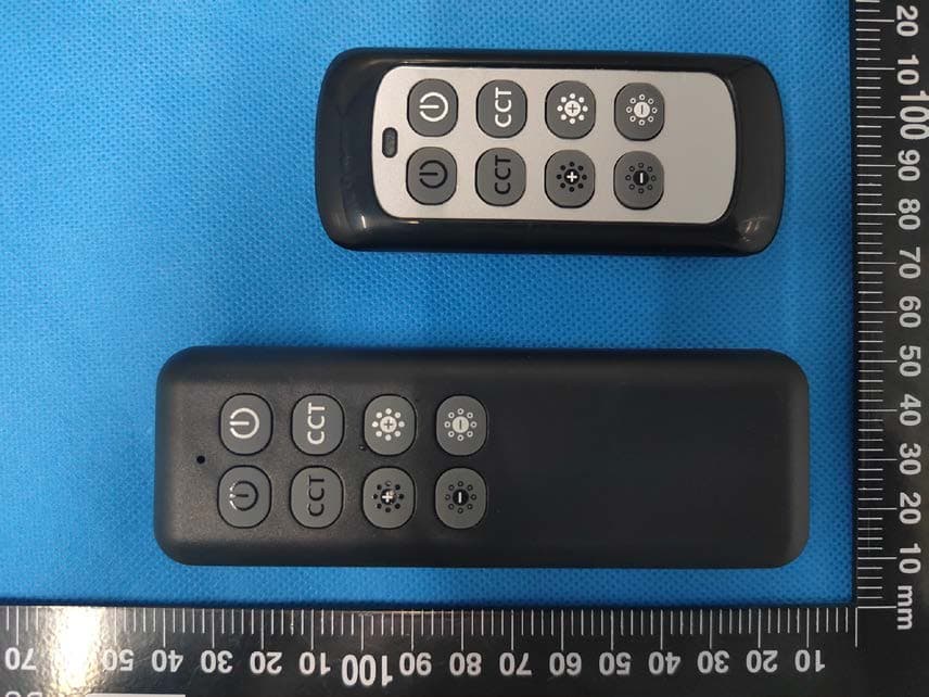
Click to zoom
Application Details
- Equipment Class
- DSC - Part 15 Security/Remote Control Transmitter
- Date of Grant
- Apr 13, 2022
- Application Purpose
- Original Equipment
- Date of Application
- Apr 13, 2022
- Equipment Note
- Remote-control Unit
- Frequency Range
- 433.97000000 - 433.97000000
- Company
- Anderson Lighting Co., Ltd.
- Country
- China
Documents & Files
Document Text
Text extracted from the exhibit documents filed with the FCC. Open a document above to read the original.
Users Manual
MF 18812 User Manual CONTENT S English ................................................................. 1 Deutsc h ................................................................. 4 Español .................................................................. 7 Français .................................................................. 10 Italiano ................................................................... 13 NOTICE: Batt eries are not included, please install 2×1.5V AAA batteries before use. Hinweis: Diese Fernbedienung enthält keine Batterien. Bitte legen Sie vor der Verwendung auch 2 × 1,5 V AAA-Batterien ein. Noticia: Este mando a distancia no incluye pilas, por favor coloque 2 pilas AAA de 1,5 V antes de usarlo. NIT:MMNIT:MMNIT:MM - 1 -- 4 -- 7 -- 2 -- 5 -- 8 -- 3 -- 6 -- 9 - Attention: Tile remote control needs to be paired before use.Achtung: Die Fernbedienung muss vor der Benutzung gekloppt werden.ATENCIÓN: El mando a distancia de6e ser emparejado antes de su uso. How to pair the remote control with the light: 1.Th e remote control should be equipped with batteries. 2.Keep long press the on-off key (the first button on the left side of the remote control) of the remote control for more than 5 seconds. And plug the power into the socket when pressing. 3.If the light flickers, it indicates that the pairing is successful. The remote control can now be used. So koppeln Sie die Fernbedienung mit der Leuchte: 1.Die Fer nbedienung sollte mit Batterien ausgestattet sein. 2.Halten Sie die Ein-/Aus-Taste (die erste Taste auf der linken Seite der Fernbedienung) der Fernbedienung Iänger als 5 Sekunden gedrückt. Und stecken Sie beim Drücken den Netzstecker in die Steckdose. 3.Wenn das Licht flackert, zeigt es an, dass die Kopplung erfolgreich ist. Die Fernbedienung kann nun verwendet werden. Cómo emparejar el control remoto con la luz: 1. El mando a distan cia debe estar equîpado con pilas. 2. Mantenga pulsada la tecla de encendido y apagado (el primer botón del lado izquierdo del mando a distancia) del mando a distancia durante más de 5 segundos. Y conecte la corriente en la toma cuando la pulse. 3. Si la luz parpadea, indica que el emparejamiento se ha realizado con éxito. El mando a distancia ya puede utilizarse.ndet werden. REMOTE CONTROLFERNBEDIENUNGMANDO A DISTANCIA HOW TO USE BENUTZUNG USO NOTICE HINWEIS SUGERENCIA WARRANTY GARANTIE GARANTÍA SPECIFICATION Name LED floor lamp Material Metal + Plastic Color Matt Black Wattage20W+7W Luminous Flux 1300LM + 300LM Dimmable Yes (5%-100% dimming) Color Temperature 3000k-6000k Lifespan40,000Hrs Adapter Voltage DC24V 1.5A Input Voltage AC100-240V 50/60Hz Protection class IP20 SPEZIFIKATION NameLED-StehIeuchte Material Metall + Kunststoff FarbeMattschwarz Wattzahl 20W + 7W Lichtstärke 1300LM + 300LM Dimmbar Ja (5%-100% dimmbarkeit) Farbtemperatur3000k-6000k Lebenserwartung 40000 Stunden Adapter-Spannung DC24V 1,5A Eingangsspannung AC100-240V 50/60Hz SchutzklasseIP20 ESPECIFICACIÓN Nombre Lámpara de piso LED Material metal + plástico Color Negro mate Potencia 20W + 7W Intensidad de la luz 1300LM + 300LM Regulable Sí (5%-100% regulable) Temperatura de color 3000k-6000k Esperanza de vida 40000 horas Voltaje del adaptador DC24V 1.5A Voltaje de entrada AC100-240V 50/60Hz Clase de protección IP20 ON / OFF Button: Short press this button to turn on the light, press it again to turn off. CCT—Color Temperature: Short press this button to select the color temperature (3000k-6000k) after turning on the light. Brightness +: Hold the button to increase the brightness. Brightness -: Hold the button to reduce the brightness. EIN/AUS-Taste: Drücken Sie kurz diese Taste, um das Licht einzuschalten, und drücken Sie sie erneut, um sie auszuschalten. CCT - Farbtemperatur: Durchschalten der Farbtemperatur.(3000k-6000k) dopo aver acceso la luce. Helligkeit +: Halten Sie die Taste gedrückt, um die Helligkeit zu erhöhen. Helligkeit -: Halten Sie die Taste gedrückt, um die Helligkeit zu reduzieren. Botón de encendido/apagado: Presione brevemente este botón para encender la luz, presiónelo nuevamente para apagar. CCT - Temperature de color: Cambiando a través de la temperatura de color. (3000k-6000k) Brillo +: Presione y mantenga presionado el botón para aumentar el brillo. Brillo -: Presione y mantenga presionado el botón para disminuir el brillo. The Remote distance is within 25ft (7.62 m). It is magnetic so that you can stick it on the lamp pipe and other magnetic surfaces. Die maximale Entfernung der Fernbedienung liegt innerhalb von 7,62 m (25ft). Sie ist magnetisch, so dass Sie Sie auf das Lampenrohr und andere magnetische Oberflächen haften können. La distancia máxima del mando a distancia es de 7,62 m (25ft). Es magnético, así que puedes fijarlo at tubo de la Iámpara y a otras superficies magnéticas. Upper butt on controls the ceiling flood light. Lower button controls the reading light. Touch and hold the button to increase brightness. Touch and hold a second time to reduce the brightness. (When reaching full brightness it will switch to reduce brightness) Die obere Taste steuert das Deckenflutlicht. Mit der unteren Taste wird das Leselicht gesteuert. Halten Sie die Taste gedrückt, um die Helligkeit zu erhöhen. Halten Sie die Taste ein zweites Mat gedrückt, um die Helligkeit zu verringern. (Wenn die volle Helligkeit erreicht ist, wird die Helligkeit reduziert) El botón superior controla el foco del techo. El botón inferior controla la luz de lectura. Presione y mantenga presionado el botón para aumentar el brillo. Presione y mantenga presionado el botõn por segunda vez para disminuir el brillo. (Cuando se alcanza el brillo total, el brillo se reduce) 1.Read the instructions before using the lamp. 2.To ensure long lifetime keep the lamp away f rom damp, hot or corrosive environments. 3.Check for transport damage after receiving the packaged lamp. Report any issues to us directly at [email protected]. 4.Do not disassemble or repair the lamp if you are not…
Text truncated - open the document above for the full version.
Cover Letter(s)
Anderson Lighting Co., Ltd. Add:7# Guangchang Road, Baisha 5th Village, Humen Town,Dongguan C i t y, Guangdong Province, China Tel: 0769-22301135 Fax: 0769-22301135 Email: [email protected] DECLARATION OF SIMILARITY Date: 2022-03-01 FEDERAL COMMUNICATIONS COMMISSION Authorization and Evaluation Division 7435 Oakland Mills Road Columbia, MD 21046 D ear Sir or Madam: We , Anderson Lighting Co., Ltd., hereby declare that the product: Remote-control Unit, FCCID:2ASGH-MF18812.model:MF18805,MF19347.2,MF18813,MF18825,MF18823,MF18826,MF18827, MF18832,MF18833,MF18834,MF18835,MF18836,MF18837,MF18838,MF18839,MF18840 and MF18812 which was tested by China Certification ICT Co., Ltd (Dongguan) with the same electromagnetic emissions and electromagnetic compatibility characteristics. The description of the differences between those models are declared as follows: They are same product, same PCB, and different product appearance, MF18805,MF19347.2,MF18813, MF18825,MF18823,MF18826,MF18827,MF18832,MF18833,MF18834,MF18835,MF18836,MF18837,MF18838 , MF18839,MF18840 are all 3V power supply, MF18805 is 12V power supply ,the rest are the same. P lease contact me should there be need for any additional clarification or information. B est Regards, Signa ture: P rinted Name: Johnson Zhu Title: Manager
External Photos
EXHIBIT B - EUT EXTERNAL PHOTOGRAPHS Model: MF18812 Model: MF18805
Internal Photos
EXHIBIT C - EUT INTERNAL PHOTOGRAPHS Model: MF18812 Antenna Model: MF18805 Antenna
Test Report
TEST REPORT Applicant: Anderson Lighting Co. Ltd. Address: Room 309,Building 1,No.2 Xisha Road,Houjie Town,Dongguan City,Guangdong Province,China . FCC ID: 2ASGH-MF18812 Product Name: Remote-control Unit Model Number: MF18812 Multiple Models: MF18805, MF19347.2, MF18813, MF18825, MF18823, MF18826, MF18827, MF18832, MF18833, MF18834, MF18835, MF18836, MF18837, MF18838, MF18839, MF18840 Standard(s): 47 CFR Part 15, Subpart C(15.231) ANSI C63.10-2013 The above equipment has been tested and found compliant with the requirement of the relative standards by China Certification ICT Co., Ltd (Dongguan) Report Number: CR22030013-00 Date Of Issue: 2022-03-15 Reviewed By: Sun Zhong Title: Manager Test Laboratory: China Certification ICT Co., Ltd (Dongguan) No. 113, Pingkang Road, Dalang Town, Dongguan, Guangdong, China Tel: +86-769-82016888 China Certification ICT Co., Ltd (Dongguan) Report No.: CR22030013-00 Page 2 of 27 Test Facility The Test site used by China Certification ICT Co., Ltd (Dongguan) to collect test data is located on the No. 113, Pingkang Road, Dalang Town, Dongguan, Guangdong, China. The lab has been recognized as the FCC accredited lab under the KDB 974614 D01 and is listed in the FCC Public Access Link (PAL) database, FCC Registration No. : 442868, the FCC Designation No. : CN1314. The lab has been recognized by Innovation, Science and Economic Development Canada to test to Canadian radio equipment requirements, the CAB identifier: CN0123. Declarations China Certification ICT Co., Ltd (Dongguan) is not responsible for the authenticity of any test data provided by the applicant. Data included from the applicant that may affect test results are marked with a triangle symbol “▲”. Customer model name, addresses, names, trademarks etc. are not considered data. Unless otherwise stated the results shown in this test report refer only to the sample(s) tested. This report cannot be reproduced except in full, without prior written approval of the Company. This report is valid only with a valid digital signature. The digital signature may be available only under the Adobe software above version 7.0. This report may contain data that are not covered by the accreditation scope and shall be marked with an asterisk “★”. China Certification ICT Co., Ltd (Dongguan) Report No.: CR22030013-00 Page 3 of 27 CONTENTS T EST FACILITY .......................................................................................................................................... 2 DECLARATIONS .......................................................................................................................................... 2 1. GENERAL INFORMATION .................................................................................................... 4 1.1 PRODUCT DESCRIPTION FOR EQUIPMENT UNDER TEST (EUT) ....................................................... 4 1.2 DESCRIPTION OF TEST CONFIGURATION ........................................................................................... 5 1.2.2 Support Equipment List and Details .............................................................................................................. 5 1.2.3 Support Cable List and Details ...................................................................................................................... 5 1.2.4 Block Diagram of Test Setup ......................................................................................................................... 5 1.3 MEASUREMENT UNCERTAINTY .......................................................................................................... 6 2. SUMMARY OF TEST RESULTS ............................................................................................ 7 3. REQUIREMENTS AND TEST PROCEDURES .................................................................... 8 3.1 AC LINE CONDUCTED EMISSIONS ...................................................................................................... 8 3.1.1 Applicable Standard ....................................................................................................................................... 8 3.1.2 EUT Setup ...................................................................................................................................................... 9 3.1.3 EMI Test Receiver Setup ............................................................................................................................... 9 3.1.4 Test Procedure ............................................................................................................................................. 10 3.1.5 Corrected Amplitude & Margin Calculation ................................................................................................ 10 3.2 RADIATION SPURIOUS EMISSIONS .................................................................................................... 11 3.2.1 Applicable Standard ..................................................................................................................................... 11 3.2.2 EUT Setup .................................................................................................................................................... 12 3.2.3 EMI Test Receiver & Spectrum Analyzer Setup ......................................................................................... 13 3.2.4 Test Procedure ............................................................................................................................................. 13 3.2.5 Corrected Amplitude & Margin Calculation ................................................................................................ 13 3.3 20 DB EMISSION BANDWIDTH: .......................................................................................................... 14 3.3.1 Applicable Standard .......................................................................................................…
Text truncated - open the document above for the full version.
Test Setup Photos
EXHIBIT D - TEST SETUP PHOTOGRAPHS Model: MF18812 Radiated Emissions Below 1G View Radiated Emissions Above 1G View Model: MF18805 Radiated Emissions Below 1G View Radiated Emissions Above 1G View
Contact Information
Applicant
Johnson Zhu(Manager)
Test Firm
CHINA CERTIFICATION ICT CO., LTD (DONGGUAN)Tanie Ou
[email protected]0086 0769 86858888
Technical Specifications
| # | Rule Parts | Frequency Range | Power Output |
|---|---|---|---|
| 1 | 15.231 | 433.97 MHz - 433.97 MHz | - |