2ASI4EMMESH2900 MHz RF Module
Les Consultants Penteract inc.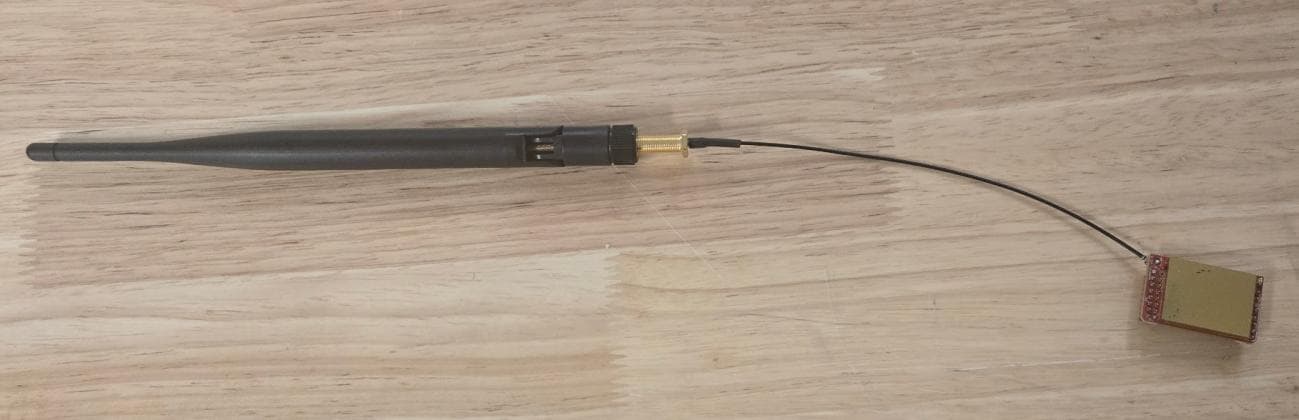
Click to zoom
Application Details
- Equipment Class
- DSS - Part 15 Spread Spectrum Transmitter
- Date of Grant
- Jan 16, 2026
- Application Purpose
- Original Equipment
- Equipment Note
- 900 MHz RF Module
- Frequency Range
- 903.24000000 - 926.76000000
- Country
- Canada
Documents & Files
Document Text
Text extracted from the exhibit documents filed with the FCC. Open a document above to read the original.
Users Manual
emMesh2 – User Guide Hardware Revision 2.2 Firmware Version 2.217 Document Version : A (05/01/2026) Table of Contents 1.Revision History 2.Trademarks & Copyrights 3.Disclaimers 4.Introduction 5.Document Related Firmware and Hardware 6.Technical Specifications 6.1 Form Factor 6.2 General Specifications 6.3 Interfaces 6.4 Specifications 6.5 Regulatory Conformity Summary 7.Technical Drawing 8.GPIOs 8.1 16-Pin Connector 8.2 8-Pin Connector 9.Design Notes 9.1 Power Supply Design 9.2 Board Layout 9.3 Antenna Performance 10.Serial Communication Protocol 10.1 Introduction 10.2 Generic Message Structure 10.3 Communication Protocol 10.4 Encryption 10.5 Message Types 11.Payload Structure 12.Regulatory Information 13.Warranty 1. Revision History RevisionDateDescription AJan 2026Creation of document 2. Trademarks & Copyrights Penteract and emMesh logos are protected properties of Les Consultants Penteract Inc. or Penteract Consulting Inc. Usage of these logos is strictly prohibited without written consent. © 2018 Penteract Consulting Inc. – All rights reserved. 3. Disclaimers Information in this document is subject to change without notice and does not represent a commitment on the part of Penteract Consulting Inc. This document is provided “as is”, without warranty of any kind, expressed or implied. 4. Introduction The em series are long-range 915 MHz radios (up to 16 km) using mesh topology to provide connectivity in areas without traditional networks. They are optimized for: ultra-low power consumption, long-range communication, large sensor networks, near-real-time monitoring. The emMesh uses the Microchip MRF89A chipset, amplified to 26 dBm, with sensitivity down to – 103 dBm. 5. Document Related Firmware and Hardware This document refers to: Hardware revision: 2.2 Firmware version: 2.217 6. Technical Specifications 6.1 Form Factor 6.2 General Specifications ParameterValue FrequenciesAmericas: 902–928 MHz Network sizeUp to 64,006 units Bandwidth19,200 bps (P2P) FHSS15.6 ms, 50 channels Internal memory4 Mbit Flash Antenna connectorU.FL (50 Ω) 6.3 Interfaces InterfaceDescription UART1 communication UART, 1 debug UART I/O10 programmable I/O pins SPIUp to 1 Mbps USARTI²C ADC2× 12-bit analog inputs (0–2 V) PWM5 PWM outputs 6.4 Specifications ParameterValue Dimensions34 × 21 × 10 mm Operating temperature–20 °C to +70 °C Storage temperature–40 °C to +85 °C Operating voltage3.3 V to 5.5 V Typical consumption5 mAh AntennaWire or U.FL port Transmit power25 dBm Sensitivity–103 dBm 6.5 Regulatory Conformity Summary RegionCertification USA (FCC Part 15.247) FCC 47 CFR Part 15 Subpart C, §15.247 Canada (ISED)RSS-247, Issue 4, July 2024, Section 6 7. Technical Drawing 8. GPIOs 8.1 16-Pin Connector PinNameTypeDescription 1GroundPGround reference 2PPROPower-Present (open-drain) 3GroundPGround reference 4TX2I/OI/O or UART TX 5BAT+P3.3–5.5 V input 6RX2I/OI/O or UART RX 7TXI/OI/O, UART TX, or I²C SDA 8AN1I/OAnalog input 9AN2I/OAnalog input 10RXI/OI/O, UART RX, or I²C SCL 11NC 12PWM2I/OPWM output 13NC 14NC 153.3VP3.3 V output (200 mA max) 16NC 8.2 8-Pin Connector PinNameTypeDescription 1nMCLRIReset (active low) 23.3VP3.3 V output 3GNDPGround 4PGDI/OProgramming data 5PGCI/OProgramming clock 6GNDPGround 7PWM1OStatus LED 8NC 9. Design Notes 9.1 Power Supply Design Single external supply required Ripple < 100 mV Peak current capability: 250 mA Add 100 μF capacitor at input 9.2 Board Layout No special constraints except antenna area Follow standard PCB practices 9.3 Antenna Performance Recommendations : Antenna vertical Keep away from metal Use external antenna if enclosure is metallic No ground plane under antenna Place module at PCB edge 10 Serial Communication Protocol 10.1 Introduction The following document refers to Penteract emToo Protocol for Generic implementation. emToo Protocol works as a global multi-layer, multi-protocol mesh type networking. Allowing multiples protocol such as WiFi, ISM, IP or Bluetooth to interact with each other transparently and be use as a unique transport layer. The protocol is defined by two mode: Simplified protocol and Advanced Protocol. Description of both mode could be found later in that document. Choosing the protocol that is more suitable for your needs can lead to simplistic to more complex implantation requirements. 10.2 Generic message structure Both mode, simplified or advanced are using the same base structure. Both are meant to be efficient on any type of transport protocol and secured in both possible encryption and integrity of datas. Every message sent thru emToo protocol must be packet for the Transport layer structure. Said transport layer is what is creating the capacity to travel on every type of protocols. Transport layers such as IP, Serial or Bluetooth are completely transparent and rely on a Mesh reality which held, depending on protocols on a system of relay which allowed a packet to switch from one type of transport to the other without the system needing to know it. This is coming with some limitation like payload size with is maintained fairly small as it allows smaller capacity type of transport such as emMesh and BLE to be able to participate as said mesh reality. Although said payload could be increased if protocol is only used in IP, knowing which device will be used as relay is fairly important to allows said behaviour and we do not recommend it. 10.3 Communication protocol A message sent must begin with 0x24 0x24 and end with 0x0D 0x0A. In addition, it must contain a size, 8 bits checksum, the message type used and the type of encryption used. In the example on Table 1, byte[1 & 2] are the sync characters which are alway, whether in simplified or advanced mode, $$. byte[3] Length: This byte is a computation of the size of the payload the msgType and itself. byte[4] Msg Type & Encryptio: This byte is created by mixing the binary values [MSB 1bits Advanced=1 Simplified=0][LSB 7 bits Encryption Type] Exemple: Encryption_Type = 0x01; Msg_…
Text truncated - open the document above for the full version.
Attestation Statements
Dated: January 5, 2026 Nemko North America, Inc. 303 River Road Ottawa ON K1V 1H2 Canada Covered Equipment Certification Attestation Letter Applicant: Les Consultants Penteract inc. FCC ID: 2ASI4EMMESH2 The applicant certifies that the equipment for which authorization is sought is not “covered” equipment prohibited from receiving an equipment authorization pursuant to section §2.903 of the FCC rules. This includes certifying that the equipment for which authorization is sought does not include cybersecurity or anti-virus software produced or provided by Kaspersky Lab, Inc. or any of its successors and assignees, including equipment with integrated Kaspersky Lab, Inc. (or any of its successors and assignees) cybersecurity or anti-virus software pursuant to DA-24-886 and KDB 986446 D01 Covered Equipment Guidance section B(2a). Note: If the equipment for which the applicant seeks authorization is produced by any of the entities identified on the current FCC Covered List, the applicant should include an explanation on why the equipment is not “covered” equipment. The applicant certifies that, as of the date of the filing of the application, the applicant is not identified on the Covered List as an entity producing “covered” equipment. Sincerely, Signature: Name: Alain Moisan Title: V-P Ingénierie Company: Les Consultants Penteract inc. Address: 2376 rue galvani, bureau 110, Quebec, G1N 4G4 Phone: 418-800-1360 Email: [email protected]
Attestation Statements
Les Consultants Penteract Inc. 2376 rue Galvani, Bureau 110 Quebec, Quebec, G1N 4G4 Canada Date: Jan, 07, 2026 Federal Communications Commission Authorization and Evaluation Division 7435 Oakland Mills Road Columbia, MD 21046 FCC ID: 2ASI4EMMESH2 FRN: 0028250603 US Agent – Attestation Statement / Part 2.911(d)(7) Les Consultants Penteract Inc certifies, that as of Jan, 07, 2026, we have designated FCC US Agent, LLC to accept service of process on our behalf for FCC ID: 2ASI4EMMESH2. Les Consultants Penteract Inc., accepts to maintain an agent of service of process in the United States for no less than one year after either the grantee has permanently terminated all marketing and importation of the applicable equipment within the U.S., or the conclusion of any Commission- related administrative or judicial proceeding involving the equipment, whichever is later. FCC US Agent, LLC, accepts as of the date of the filing of this application, the obligation of being the designated agent for the purpose of accepting service of process on behalf of Les Consultants Penteract Inc. for FCC ID: 2ASI4EMMESH2. Designated Agent Information: Company Name: FCC US Agent, LLC FRN: 0033402884 Address: 3722 Illinois Avenue, Saint Charles, IL, 60174, USA Contact Person: Tim Payne Phone: 708-571-3148 Email: [email protected] Sincerely, Company: Les Consultants Penteract Inc. Designated Agent: FCC US Agent, LLC Company Representative: Alain Moisan Designated Agent Representative: Tim Payne Signature: Signature:
Cover Letter(s)
Dated: January 5, 2026 Nemko North America, Inc. 303 River Road, Ottawa, Ontario, Canada K1V 1H2 Attn: Director of Certification Appointment of Agent for FCC Certification Application Dear Director of Certification, This letter formally appoints Spencer Zhong of Nemko Canada, Inc. located at 303 River Road, Ottawa, Ontario, Canada K1V 1H2, as our authorized agent to represent us in the application process for equipment certification. We confirm that the submitted documents accurately depict the device or system seeking certification. Additionally, we guarantee that all units produced, imported, or marketed, as defined by FCC regulations, will possess a label identical to the one submitted with this application. By signing below, we certify that neither our company nor any party involved in the application is subject to denial of federal benefits, including FCC benefits, as outlined in Section 5301 of the Anti- Drug Abuse Act of 1988 (21 U.S.C. §862) due to a conviction for possession or distribution of a controlled substance. Furthermore, no party involved in the application, as defined in 47 CFR 1.2002 (b), is subject to denial of federal benefits, including FCC benefits. We attest to the truth and accuracy of the information provided to the FCC to the best of our knowledge (47 CFR 2.911 (d)) and acknowledge our responsibilities as a grantee regarding certified equipment (47 CFR 2.909). In instances where our authorized agent signs the application for certification on our behalf, we understand that Nemko North America, Inc. remains solely responsible for adhering to the terms and conditions for certification as specified by Nemko Canada Inc. Agency agreement expiration date: December 29, 2026 *Up to 12 months Sincerely, Signature: Name: Alain Moisan Title: V-P Ingénierie Company: Les Consultants Penteract inc. Address: 2376 rue galvani, bureau 110, Quebec, G1N 4G4 Phone: 418-800-1360 Email: [email protected]
Cover Letter(s)
Dated: January 5, 2026 Nemko North America, Inc. 303 River Road, Ottawa, Ontario, Canada K1V 1H2 Attn: Director of Certification Confidentiality Request Letter – FCC FCC ID: 2ASI4EMMESH2 Pursuant to FCC 47 CFR 0.457(d)(1)(ii) and 0.459 and FCC guidance published in KDB 726920, we hereby request confidential treatment of information accompanying this application as outlined below. Long Term Confidentiality (LTC) request We request the exhibits selected below as long term confidential be withheld from public view permanently: Selection Exhibit name ☒ Block Diagrams ☒ Operation Description / Theory of Operation ☒ Parts List & Placement / BOM ☒ Schematics Justification for Confidentiality The development of this product represents a significant investment and a strategic competitive differentiator for our company. Unrestricted public access to its design specifics would negate this hard-earned advantage, leading to considerable financial hardship. The content herein contains trade secrets and proprietary information not typically released to the public. Disclosure of this information could severely impact the applicant and provide an unfair advantage to competitors. The Applicant acknowledges that, under Rule 0.457(d)(1)(ii), this Application and all associated materials will not be disclosed before the Grant date. Sincerely, Signature: Name: Alain Moisan Title: VP Engineering Company: Les Consultants Penteract Inc Address: 2376 rue Galvani, bureau 110, Quebec, G1N 4G4 Canada Phone: 418-800-1360 Email: [email protected]
Cover Letter(s)
Dated: 05 January 2026 Federal Communications Commission Equipment Authorization Branch 7435 Oakland Mills Road Columbia, MD 21046 Request for Single Modular Modular Approval FCC ID: 2ASI4EMMESH2 The following attestation addresses the requirements to support modular approval: Modular approval requirement Yes (provide brief statement) No * (1) The radio elements must have its own radio frequency circuitry shielded. The physical crystal and tuning capacitor(s) may be located external to the shield, but must be on the module assembly The module contains a metal shield which covers all RF components and circuitry. The shield is located on the top of the board next to antenna connector – (2) The module must have buffered modulation/data inputs (if provided) to ensure that the device will comply with FCC requirements under conditions of excessive data rates or over-modulation. Data to the modulation circuit is buffered – (3) The module must contain its own power supply regulation on the module. This is intended to ensure that the module will comply with FCC requirements regardless of the design of the power supplying circuitry in the device into which the module is installed. The module contains its own power supply regulation. Please refer to schematic filed with this application – (4) The module must comply with the antenna and transmission system requirements of §§ 15.203, 15.204(b), 15.204(c), 15.212(a), and 2.929(b). The antenna must either be permanently attached or employ a ‘‘unique’’ antenna coupler (at all connections between the module and the antenna, including the cable). The ‘‘professional installation’’ provision of § 15.203 is not applicable to modules but can apply to limited modular approvals under paragraph 15.212(b). 15.212(a)(1)(iv) The module connects to its antenna using an UFL connector which is considered a non-standard connector. A list of antennas tested and approved with this device may be found in user’s manual provided with the application – (5) The module must demonstrate compliance in a stand-alone configuration, the module must not be inside another device during testing. This is intended to demonstrate that the module can comply with Part 15 emission limits regardless of the device into which it is eventually installed. The module was tested stand-alone as shown in test setup photographs filed with this application – (6) The module must be labelled with its permanently affixed FCC ID label, or use an electronic display (See KDB Publication 784748 about labelling requirements) There is a label on the module as shown in the labeling exhibit filed with this application. Host specific labeling instructions are shown in the installation manual filed with this application. – (7) The module must comply with all specific rule or operating requirements applicable to the transmitter, including all the conditions provided in the integration instructions by the grantee. A copy of these instructions must be included in the application for equipment authorization. The module complies with FCC Part 15C requirements. Instructions to the OEM installer are provided in the installation manual filed with this application – (8) The module must comply with any applicable RF exposure requirements The module meets Mobile exclusion levels as shown in the RF exposure information filed with this application. – Sincerely, Signature: Name: Alain Moisan Title: V-P Ingénierie Company: Les Consultants Penteract inc. Address: 2376 rue galvani, bureau 110, Quebec, G1N 4G4 Phone: 418-800-1360 Email: [email protected]
External Photos
External Photographs Exhibit Model Number: EMMESH2 FCC ID: 2ASI4EMMESH2 IC: 24776-EMMESH2 Applicant: Les Consultants Penteract Inc. Date: January 5, 2026 Purpose This exhibit provides color photographs of the external appearance of the subject device, as required by FCC §2.1033(b)(7) and ISED RSS-GEN Section 3.2(e). The photos demonstrate the external design, dimensions, and location of regulatory labels and antennas (if visible). Notes • All external photographs are of the final production version of the device. • No digital modifications were made, aside from cropping or brightness correction to improve visibility. • Dimensions: 35x20x9 mm (excluding 85mm wire antenna) Photo Guidelines All images should be: • High resolution (≥300 DPI recommended) • In color • Clear and unaltered (no obstructions, watermarks, or filters) • Showing the actual production unit (or final prototype identical in construction) Required Views Include the following views (with file names or images inserted as applicable): 1. Front View 2. Rear View 3. Left Side View 4. Right Side View 5. Top View 6. Bottom View 7. Label Location Close-Up 8. External Antenna (if applicable)
ID Label/Location Info
Label and Label Location Exhibit Model Number: emMesh2 FCC ID: 2ASI4EMMESH2 IC: 24776-EMMESH2 Applicant: Les Consultants Penteract inc. Date: January 5, 2026 1. Label Information The product will bear a permanent nameplate or etched label showing the required regulatory identifiers. The label includes: • FCC ID: 2ASI4EMMESH2 • IC: 24776-EMMESH2 Sample Label Format Text height and contrast shall comply with FCC §2.925 and ISED RSS-GEN. 2. Label Location The label is located on the top of the device. Label Location Photo 3. Permanence of Label The label is: • Permanently affixed to the product housing using one of the following: o Adhesive label (durable under normal use, per UL 969 or equivalent) • Visible to the user under normal operating conditions
Internal Photos
Internal Photographs Exhibit Model Number: EMMESH2 FCC ID: 2ASI4EMMES2 IC: 24776-EMMESH2 Applicant: Les Consultants Penteract Inc. Date: January 9, 2026 Purpose This exhibit provides clear and detailed internal photographs of the subject device to show the placement and construction of all internal components related to RF circuitry, shielding, antennas, power circuitry, and modular components, as required under FCC §2.1033(b)(7) and ISED RSS-GEN Section 3.2(e). Notes • All photos are representative of the production unit. • No photos have been digitally altered except for cropping or brightness adjustments to improve visibility. 1. Overview of Main PCB (Component Side) 2. Overview of Main PCB (Solder Side) 3. Shielding
RF Exposure Info
www.nemko.com Nemko Canada Inc., a testing laboratory, is accredited by ANSI National Accreditation Board (ANAB). The test results included in this report are within the scope of this accreditation. The ANAB symbol is an official symbol of the ANSI National Accreditation Board, used under licence. FCC and ISED RSS-102– MPE Calculation; Date: June 2025 RF Exposure Compliance – MPE Calculation Report C h o o s e S c a n d i n a v i a n t r u s t Applicant information: Les Consultants Penteract Inc. Product information: Model number (HVIN): EMMESH2 Model name (PMN): EMMESH2 Product type: Mobile or Fixed Device Device category Consumer Device for General Population/Uncontrolled Exposure FCC Identification: FCC ID: 2ASI4EMMESH2 ISED certification number: IC: 24776-EMMESH2 Date of issue: January 9, 2026 Compliance Specifications: FCC 47 CFR Part 1 Subpart I, §§1.1307, 1.1310 FCC 47 CFR Part 2 Subpart J, §§2.1091, 2.1093 FCC KDB 447498 D01 General RF Exposure Guidance v06 FCC KDB 865664 D01 RF Exposure Procedures and Equipment Authorization Policies ISED Canada RSS-102 Issue 6 December 15, 2023 MPE calculation report Product info: FCC ID: 2ASI4EMMESH2 IC: 24776-EMMESH2 Model: EMMESH2 Page 2 of 7 Test locations of Nemko Canada Inc. Ottawa site Montréal site GTA Cambridge site Facility address 303 River Road Ottawa, Ontario Canada K1V 1H2 Tel: +1 613 737 9680 Fax: +1 613 737 9691 292 Labrosse Avenue Pointe-Claire, Québec Canada H9R 5L8 Tel: +1 514 694 2684 Fax: +1 514 694 3528 1-130 Saltsman Drive Cambridge, Ontario Canada N3E 0B2 Tel: +1 519 650 4811 Test site identifier - FCC CA2040 CA2041 CA0101 Test site identifier – ISED Canada 2040A-4 2040G-5 24676 ANAB File Number AT-3195 AT-3193 AT-3194 Andrey Adelberg Senior EMC/Wireless Specialist Prepared by Signature Limits of responsibility The results presented in this report apply solely to the specific device model tested and are valid only for the operating conditions and installation requirements specified herein. Testing was conducted in accordance with ISO/IEC 17025:2017 requirements, and all results fall within the scope of Nemko Canada's accreditation. This MPE evaluation is based on the maximum power levels and operating conditions specified. Any modifications to the device hardware, software, or installation that could affect RF output power or antenna characteristics may invalidate this compliance demonstration. Copyright notification This report may be reproduced by the applicant in its entirety for regulatory submission and internal use. Any use of this report by third parties, including reliance on its contents or decisions made based on it, is solely at the risk of those third parties. Nemko Canada Inc. assumes no responsibility for any damages incurred by third parties as a result of actions taken based on this report. © Nemko Canada Inc. All rights reserved. MPE calculation report Product info: FCC ID: 2ASI4EMMESH2 IC: 24776-EMMESH2 Model: EMMESH2 Page 3 of 7 1. Executive Summary This report presents the Maximum Permissible Exposure (MPE) analysis for [Product Name] to demonstrate compliance with FCC and ISED RF exposure requirements. The evaluation considers both single transmitter operation and simultaneous multi-transmitter scenarios where applicable. 2. Key Findings Compliance status Complies Critical separation distances 20 cm Special conditions or limitations N/A MPE calculation report Product info: FCC ID: 2ASI4EMMESH2 IC: 24776-EMMESH2 Model: EMMESH2 Page 4 of 7 MPE calculations for stand-alone transmission Device Classification Requirements Portable Device Definition (§2.1093) Devices designed for use by a person where the radiating structure is within 20 cm of the user's body require SAR evaluation rather than MPE calculation. Mobile Device Definition Devices installed in vehicles or with permanently installed antennas may use MPE calculations if minimum separation distances can be established. Fixed/Base Station Definition Stationary transmitters with controlled access to antenna locations may use MPE calculations for both occupational and general population exposure scenarios. 3. References, definitions and limits for FCC FCC §2.1091(d) (2) For operations within the frequency range of 300 kHz and 6 GHz (inclusive), the limits for maximum permissible exposure (MPE), derived from whole-body SAR limits and listed in Table 1 in paragraph (e)(1) of this section, may be used instead of whole-body SAR limits as set forth in paragraphs (a) through (c) of this section to evaluate the environmental impact of human exposure to RF radiation as specified in §1.1307(b) of this part, except for portable devices as defined in §2.1093 of this chapter as these evaluations shall be performed according to the SAR provisions in §2.1093. Table 1: §1.1310(e)(1)—Power Density Limits for Maximum Permissible Exposure (MPE) Frequency range (MHz) Power density (mW/cm 2 ) Averaging time (minutes) (i) Limits for Occupational/Controlled Exposure 0.3–3.0 *(100) ≤6 3.0–30 *(900 / f 2 ) <6 30–300 1.0 <6 300–1500 f / 300 <6 1500–100000 5 <6 (ii) Limits for General Population/Uncontrolled Exposure 0.3–1.34 *(100) <30 1.34–30 *(180 / f 2 ) <30 30–300 0.2 <30 300–1500 f / 1500 <30 1500–100000 1.0 <30 Notes: f = frequency in MHz. * = Plane-wave equivalent power density. MPE calculation report Product info: FCC ID: 2ASI4EMMESH2 IC: 24776-EMMESH2 Model: EMMESH2 Page 5 of 7 4. References, definitions and limits for ISED RSS-102 Section 5.3.2 The power density reference levels, and associated reference period for devices employed by the general public (uncontrolled environment) and controlled-use devices (controlled environment) are specified in table below. Note that the power density limits specified in this table apply to whole body exposure conditions. Table 2: RSS-102— Power density limits Frequency range (MHz) Power density (W/m 2 ) Power density (mW/cm 2 ) Reference Period (minutes) Limits for controlled-use devices (controlled environment) 10–20 10 1 6 20…
Text truncated - open the document above for the full version.
Test Report
www.nemko.com Nemko Canada Inc., a testing laboratory, is accredited by ANSI National Accreditation Board (ANAB). The tests included in this report are within the scope of this accreditation. The ANAB symbol is an official symbol of the ANSI National Accreditation Board, used under licence. ANAB File Number: AT-3195 (Ottawa); AT-3193 (Pointe-Claire); AT-3194 (Cambridge) FCC 15.247 and RSS-247; Date: October 21, 2025 C h o o s e S c a n d i n a v i a n t r u s t RADIO TEST REPORT Report ID: Project number: REP137810 PRJ0090190 Type of assessment: Modular approval Type of radio equipment: Spread Spectrum/Digital Device (902–928 MHz) Equipment class: FHSS - frequency hopping spread spectrum and DTS - digital transmission systems Applicant: Description of product: Les Consultants Penteract Inc. Wireless radio module for IoT, low power in ISM band 902–928 MHz Model numbers(s)/HVIN(s): Model name(s) / Product marketing name (PMN): EMMESH2 EMMESH2 FCC identifier: ISED certification number: FCC ID: 2ASI4EMMESH2 IC: 24776-EMMESH2 Specifications: FCC 47 CFR Part 15 Subpart C, §15.247 RSS-247, Issue 4, July 2025, Section 6 Date of issue: January 9, 2026 Atefeh Beiginezhad, EMC/RF Specialist Tested by Signature David Duchesne, EMC/RF Lab Manager Reviewed by Signature Report reference ID: REP137810 Page 2 of 40 Lab locations Company name Nemko Canada Inc. Facilities Ottawa site: 303 River Road, Ottawa, ON, Canada, K1V 1H2 Tel: +1 613 737 9680 Test site registration number: CA2040 Montréal site: 292 Labrosse Avenue, Pointe-Claire, QC, Canada, H9R 5L8 Tel: +1 514 694 2684 Test site registration number: CA2041 Cambridge site: 1-130 Saltsman Drive, Cambridge, ON, Canada, N3E 0B2 Tel: +1 519 650 4811 Test site registration number: CA0101 Website www.nemko.com Limits of responsibility Note that the results contained in this report relate only to the items tested and were obtained in the period between the date of initial receipt of samples and the date of issue of the report. This test report has been completed in accordance with the requirements of ISO/IEC 17025. All results contained in this report are within Nemko Canada’s ISO/IEC 17025 accreditation. Copyright notification Nemko Canada Inc. authorizes the applicant to reproduce this report provided it is reproduced in its entirety and for use by the company’s employees only. Any use which a third party makes of this report, or any reliance on or decisions to be made based on it, are the responsibility of such third parties. Nemko Canada Inc. accepts no responsibility for damages, if any, suffered by any third party as a result of decisions made or actions based on this report. © Nemko Canada Inc. Report reference ID: REP137810 Page 3 of 40 Table of Contents Table of Contents ......................................................................................................................................................................................................... 3 Report summary ................................................................................................................................................................................. 4 1.1 Test specifications .................................................................................................................................................................................................... 4 1.2 Test methods ............................................................................................................................................................................................................ 4 1.3 Exclusions ................................................................................................................................................................................................................. 4 1.4 Statement of compliance .......................................................................................................................................................................................... 4 1.5 Test report revision history ....................................................................................................................................................................................... 4 Engineering considerations ................................................................................................................................................................. 5 2.1 Modifications incorporated in the EUT for compliance ............................................................................................................................................ 5 2.2 Technical judgment .................................................................................................................................................................................................. 5 2.3 Model variant declaration ........................................................................................................................................................................................ 5 2.4 Deviations from laboratory tests procedures .......................................................................................................................................…
Text truncated - open the document above for the full version.
Contact Information
Applicant
Alain Moisan(VP enginering)
[email protected]Fax: 1-581-702-0256
Technical Contact
FCC US Agent, LLCTim Payne
3722 Illinois Avenue · Saint Charles, 60174 · United States
Test Firm
Nemko Canada Inc. (Montreal)Charles Neal
[email protected]Fax: 613-737-9691
Technical Specifications
| # | Rule Parts | Frequency Range | Power Output |
|---|---|---|---|
| 1 | 15C | 903.24 MHz - 926.76 MHz | 285.10 mW |