2ASK5-WAVUBTT58Wavence UBT-T 5.8 -6GHz HP
Nokia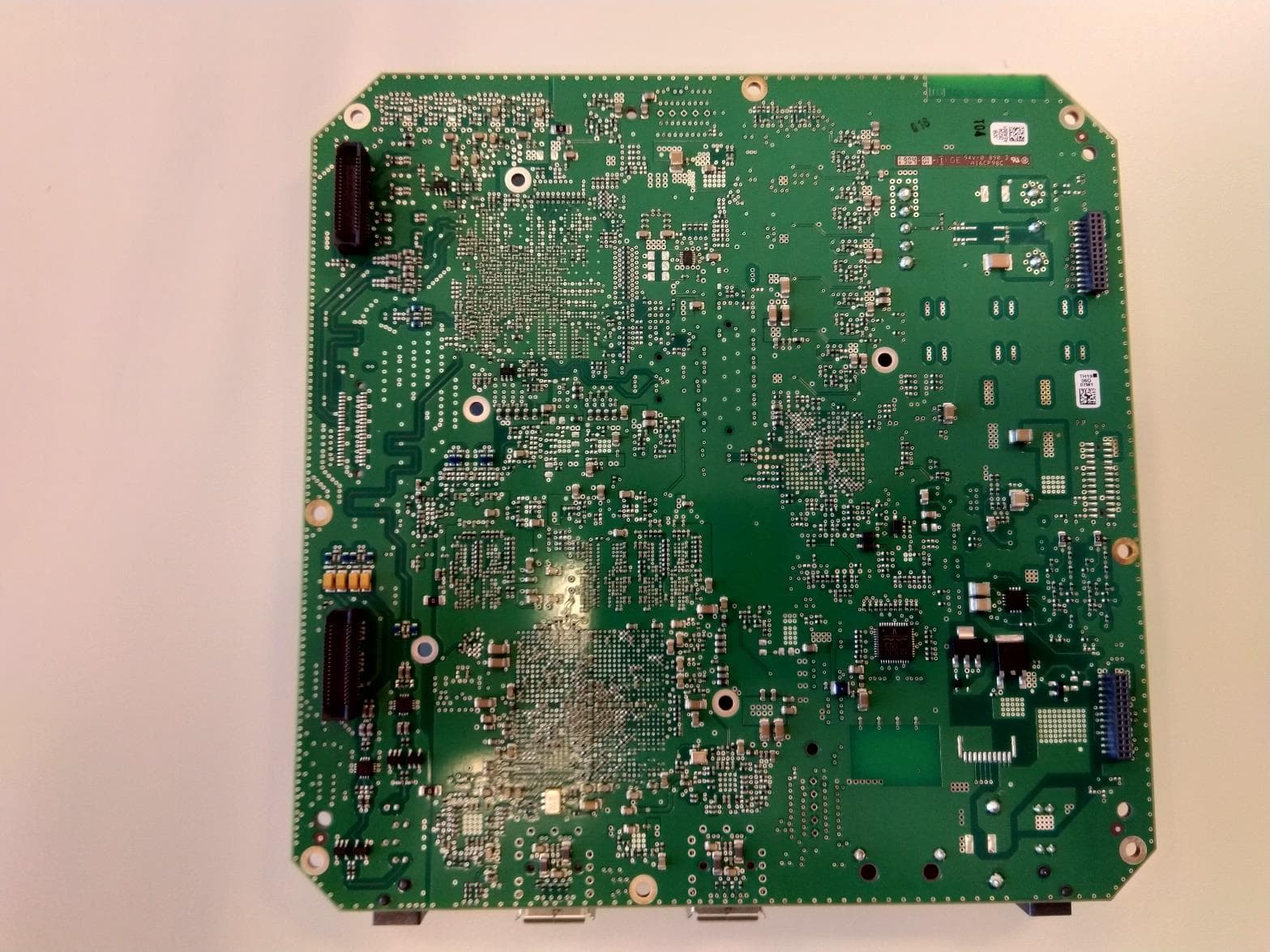
Click to zoom
Application Details
- Equipment Class
- NII - Unlicensed National Information Infrastructure TX
- Date of Grant
- Jun 01, 2020
- Application Purpose
- Original Equipment
- Date of Application
- Jun 01, 2020
- Equipment Note
- Wavence UBT-T 5.8 -6GHz HP
- Frequency Range
- 5741.00000000 - 5834.00000000
- Company
- Nokia
- Country
- United States
Documents & Files
Document Text
Text extracted from the exhibit documents filed with the FCC. Open a document above to read the original.
Users Manual
4 FCC part 15 Subpart E 4.1 Wavence unlicensed radio The 2ASK5-WAVUBTS58/25881-WAVUBTS58 (UBT-S) unlicensed radio provides fast deployment of service with microwave radio. No license and small antennas (no FCC and ISED requirements) allow immediate turn-up. After the license is received, the unlicensed UBT-S radio can be easily converted to the 6 GHz licensed band. The 2ASK5-WAVUBTT58/25881-WAVUBTT58 (UBT-T) unlicensed radio provides fast deployment of service with microwave radio. No license and small antennas (no FCC and ISED requirements) allow immediate turn-up. After the license is received, the unlicensed UBT-T radio can be easily converted to the 6 GHz licensed band. The 2ASK5-WAVUBTS58/25881-WAVUBTS58, and 2ASK5-WAVUBTT58/25881- WAVUBTT58 unlicensed radios operate in the 5725-5850 U-NII-3 band in accordance with FCC Part 15.407 and ISED RSS-247. These unlicensed radios, although operating in the same band as other spread spectrum radio, operates using narrower bandwidths than spread spectrum, allowing higher power at the tuned frequency. This design will provide greater immunity to interference from other unlicensed radios. 4.2 FCC Class B and ISED ICES-003 compliance statement The 2ASK5-WAVUBTS58/25881-WAVUBTS58, and 2ASK5-WAVUBTT58/25881- WAVUBTT58 unlicensed radios have been tested and found to comply with the limits for a Class B digital device, pursuant to Part 15 of the FCC Rules and ISED ICES-003. This equipment has been tested and found to comply with the limits for a Class B digital device, pursuant to part 15 of the FCC Rules. These limits are designed to provide reasonable protection against harmful interference in a residential installation. This equipment generates, uses and can radiate radio frequency energy and, if not installed and used in accordance with the instructions, may cause harmful interference to radio communications. However, there is no guarantee that interference will not occur in a particular installation. If this equipment does cause harmful interference to radio or television reception, which can be determined by turning the equipment off and on, the user is encouraged to try to correct the interference by one or more of the following measures: • Reorient or relocate the receiving antenna. • Increase the separation between the equipment and receiver. • Connect the equipment into an outlet on a circuit different from that to which the receiver is connected. • Consult the dealer or an experienced radio/TV technician for help. FCC part 15 Subpart EUBT/MSS Product Information Manual 26© 2020 Nokia. Nokia confidential.3DB 19600 AEAA TQZZA Issue: 01 4.3 FCC Class B and ISED ICES-003 requirements f WARNING! Regulatory compliance warning: Physical changes or modifications to the 2ASK5- WAVUBTS58/25881-WAVUBTS58, and 2ASK5-WAVUBTT58/25881-WAVUBTT58 (unlicensed) radio are strictly prohibited. Avertissement pour conformité réglementaire: changements physiques ou modifications sur les radios 2ASK5-WAVUBTS58/25881-WAVUBTS58, et 2ASK5- WAVUBTT58/25881-WAVUBTT58 (sans licence) sont strictement interdit. f CAUTION! Changes or modifications not expressly approved by Nokia could void the authority to operate the 2ASK5-WAVUBTS58/25881-WAVUBTS58, and 2ASK5- WAVUBTT58/25881-WAVUBTT58 (unlicensed) radio. f CAUTION! Installation, Turn-Up, Maintenance, and Operation Instruction supplied with the 2ASK5- WAVUBTS58, and 2ASK5-WAVUBTT58 (unlicensed) radio requires strict adherence for continued part 15 of the FCC Rules compliance. Installation, Turn-Up, Maintenance, and Operation Instruction supplied with the 25881- WAVUBTS58, and 25881-WAVUBTT58 (unlicensed) radio requires strict adherence for continued ISED RSS-247 and ISED ICES-003 compliance These devices comply with part 15 of the FCC Rules: 2ASK5-WAVUBTS58, and 25881- WAVUBTT58. These devices comply with ISED RSS-247 and ISED ICES-003: 25881- WAVUBTS58, and 25881-WAVUBTT58. Operation is subject to the following three conditions: (1) These devices may not cause harmful interference. (2) These devices must accept any interference received, including interference that may cause undesired operation. (3) These devices must be professionally installed. Cet appareil radio est conforme Á ISED RSS-247 et ISED ICES-003 (25881- WAVUBTS58, et 25881-WAVUBTT58). Son fonctionnement respecte les trois conditions suivantes: 1) cette radio ne cause pas d"interférences néfastes, 2) cette radio peut recevoir des interférences, ainsi que des interférences qui peuvent causer des opérations non désirées, et 3) cette radio doit être installée par des Professionnels. UBT/MSS Product Information ManualFCC part 15 Subpart E 3DB 19600 AEAA TQZZA Issue: 01© 2020 Nokia. Nokia confidential.27 9 UBT-S and UBT-T 5.8GHz (unlicensed) radios The 2ASK5-WAVUBTS58/25881-WAVUBTS58 (UBT-S) and 2ASK5- WAVUBTT58/25881-WAVUBTT58 (UBT-T) unlicensed radio provides fast deployment of service with microwave radio. No license and small antennas (no FCC and ISED requirements) allow immediate turn-up. After the license is received, the 2ASK5- WAVUBTS58, and 2ASK5-WAVUBTT58 radios can be easily converted to the 6 GHz licensed band. The 2ASK5-WAVUBTS58/25881-WAVUBTS58 and 2ASK5-WAVUBTT58/25881- WAVUBTT58 unlicensed radios operate in the 5725-5850 U-NII-3 band in accordance with FCC Part 15.407 and ISED RSS-247. This unlicensed radio, although operating in the same band as a spread spectrum radio, operates using narrower bandwidths than spread spectrum. FCC class B and ISED ICES-003 compliance statement The 2ASK5-WAVUBTS58 and 2ASK5-WAVUBTT58 unlicensed radios have been tested and found to comply with the limits for a Class B digital device, pursuant to Part 15 of the FCC Rules. The 25881-WAVUBTS58, and 25881-WAVUBTT58 unlicensed radios have been tested and found to comply with the limits for a Class B digital device, pursuant to ISED ICES-003. This equipment has been tested and found to comply with the limits for a Class B digital device, pursuant to part 15 of the FCC Ru…
Text truncated - open the document above for the full version.
Cover Letter(s)
1 Software Configuration Description 1.1 User-Configuration Guide 1. Describe the user configurations permitted through the UI. If different levels of access are permitted for professional installers, system integrators or end-users, describe the differences. Access levels for professional installers: • Administrator – Full access, including security settings • Operator – Network level operation. Not able to configure the radio parameters, • Craftsperson – General in charge of installation and maintenance at radio level. Can change radio parameters. • Viewer – Only allowed read access to the contents of the NE. No provisioning capability a. What parameters are viewable and configurable by different parties? The Administrator and the Craftsperson are the only parties to have access of the radio configurable parameters. They can set the modulation, frequency, and TX power of the radio. The settable parameters are limited within the certification parameters through the license key and the control of the Administrator (customer). The operator and the viewer have no access to provision radio parameters. All parameters are viewable. b. What parameters are accessible or modifiable by the professional installer or system integrators? The professional installer in this case is considered as the Craftsperson. He has access to all radio parameters, such as modulation, power, and frequency. The boundaries of operation for these parameters are restricted through the license string. Password management to the craftsperson is provided by the administrator. 1) Are the parameters in some way limited, so that the installers will not enter parameters that exceed those authorized? All parameters are restricted by software to their authorized ranges. The radio parameter limitations are restricted in software due to the license key. If a radio is licensed and set for operation in the unlicensed band the frequency limits are bounded to 5725 – 5850. Additional protection is provided against operating outside of the desired frequency range with highly selective RF filters that are installed as part of the equipment. Modulation limits are always restricted to be within the range of the certified modulations. Equipment arrives from the factory with the TX power set at or below 1 watt (based on application). Operation has limited control to slightly adjust the power based on losses in branching networks. 2) What controls exist that the user cannot operate the device outside its authorization in the U.S.? The equipment is installed as part of a professional installation. License key and provisioning limitations are controls used to restrict operation outside the authorized limits. c. What parameters are accessible or modifiable by the end-user? Same as installer, or Craftsperson 1) Are the parameters in some way limited, so that the user or installers will not enter parameters that exceed those authorized? Same as installer, or Craftsperson 2) What controls exist so that the user cannot operate the device outside its authorization in the U.S.? Same as installer, or Craftsperson d. Is the country code factory set? Can it be changed in the UI? Country codes are not supported. The parameters defined for authorized operation in the U.S. are the same for all countries. 1) If it can be changed, what controls exist to ensure that the device can only operate within its authorization in the U.S.? NA e. What are the default parameters when the device is restarted? The configured parameters are retained when the device is restarted. 2. Can the radio be configured in bridge or mesh mode? If yes, an attestation may be required. Further information is available in KDB Publication 905462 D02. No. Radio cannot be configured in bridge or mesh mode. Operation in frequency bands that require DFS is not supported. 3. For a device that can be configured as a master and client (with active or passive scanning), if this is user configurable, describe what controls exist, within the UI, to ensure compliance for each mode. If the device acts as a master in some bands and client in others, how is this configured to ensure compliance? NA 4. For a device that can be configured as different types of access points, such as point-to-point or point-to-multipoint, and use different types of antennas, describe what controls exist to NA ensure compliance with applicable limits and the proper antenna is used for each mode of operation. (See Section 15.407(a))
Cover Letter(s)
1 Software Security Description 1.1 General Description Alcatel-Lucent Answers 1. Describe how any software/firmware updates for elements than can affect the device’s RF parameters will be obtained, downloaded, validated and installed. For software that is accessed through manufacturer’s website or device’s management system, describe the different levels of security as appropriate. Software is obtained only from the manufacturer’s website after proper authentication and authorization of the customer account. The user is required to have administrator-level privileges in order to activate the new software on the device. 2. Describe the RF parameters that are modified by any software/firmware without any hardware changes. Are these parameters in some way limited such that any other software/firmware changes will not allow the device to exceed the authorized RF characteristics? 1. TX Power 2. Modulation 3. Channel bandwidth 4. TX/RX RF frequency The hardware supports parameter settings that could exceed the authorized RF characteristics but the setting ranges are limited by the authorized software. 3. Describe in detail the authentication protocols that are in place to ensure that the source of the RF-related software/firmware is valid. Describe in detail how the RF-related software is protected against modification. All software is provided with MD5 checksums to validate the integrity. 4. Describe in detail any encryption methods used to support the use of legitimate RF-related software/firmware. Software is provided by the manufacturer in compressed, compiled object form. 5. For a device that can be configured as a master and client (with active or passive scanning), explain how the device ensures compliance for each mode? In particular if the device acts as master in some band of operation and client in another; how is compliance ensured in each band of operation? N/A, Master/client operation is not supported 1.2 Third-Party Access Control 1. Explain if any third parties have the capability to operate a U.S.- sold device on any other regulatory domain, frequencies, or in any manner that may allow the device to operate in violation of the device’s authorization if activated in the U.S. Device is generally sold only to service providers, where equipment access is well controlled.. Operation outside of the certification limits is restricted through software as described in 2.1.1.b.1). 2. Describe, if the device permits third-party software or firmware installation, what mechanisms are provided by the manufacturer to permit integration of such functions while ensuring that the RF parameters of the device cannot be operated outside its authorization for operation in the U.S. In the description include what controls and/or agreements are in place with providers of third-party functionality to ensure the devices’ underlying RF parameters are unchanged and how the manufacturer verifies the functionality. Use of third-party software is not supported. Software is supplied by the manufacturer only in compiled object form. Source code is not publicly available. 3. For Certified Transmitter modular devices, describe how the module grantee ensures that host manufacturers fully comply with these software security requirements for U-NII devices. If the module is controlled through driver software loaded in the host, describe how the drivers are controlled and managed such that the modular transmitter RF parameters are not modified outside the grant of authorization. NA
Cover Letter(s)
IUETKIA April29,202A Nemko North America Inc. Attn: Director of Certification 303 River Road Ottawa, Ontario, Canada K1V 1H2 Authoritv to Act as Asent FCC On our behalf, I appoint Chip Fleury and/or Juan Gonzalez, Nemko USA Inc, 2210 Fanday Avenue, STE 150, Carlsbad, CA 92008, to act as our agent in the preparation of this application for equipment certification. I certifu that submitted documents properly describe the device or system for which equipment certification is sought. I also certify that each unit manufactured, imported or marketed, as defined in FCC regulations will have affixed to it a label identical to that submitted for approval with this application. In signing this letter, Applicant certifies that neither the applicant nor any party to the application is not subject to a denial of Federal benefits, that include FCC benefits, pursuant to Section 5301 of the Anti- Drug Abuse Act of 1988, 21 U.S.C. g 862 because of a conviction for possession or distribution of a controlled substance. See 47 CFR 1.2002(b) for the definition of a "party" for these purposes. For instances where our authorized agent signs the application for certification on our behalf, I acknowledge that all responsibility for complying with the terms and conditions for certification, as specified by Nemko North America Inc., still resides Radius Networks, lnc., 1228 31st St. SW, Suite 2, Washington D.C. 2AAA7. Dated this 29th Day ol ,2020 Aoril Title: Netu.ork Integration Engineer 29 -0 4 -2O20 - TypeDoclDHere 1J1. Print Name: Paul A. O Nokia 2020
Cover Letter(s)
May 7,2024 Nemko Canada Inc. 303 fuver Road Ottawa, ON Canada KMH2 REOUEST FOR CONFIDENTIALITY Name of Applicant: Nokia USA Address: City: Country: FCC ID. IC ID: Pursuant to Sections A.457 (d) and 0 .459 of the commission's rules and Industry of Canada Regulations, we hereby request that the following documents be held under confidentiality. LONG TERM: 1. Block Diagrams. 2. Parts Lists (Bill of Materials or BOMs). 3. Schematics. 4. Photographs. The above information contains trade secrets and proprietary information not customarily released to the public. The public disclosure of this information migtrt be harmful to the applicant and provide unjustified benefits to its competitors. Dated: 05-07-2020 Paul A. Lorenz Title: Network Intesration Engineer 32'10 Olympus Blvd Dallas, TX 75019 USA 2ASKs-WAVUBTTSS 25881-WAVUBTT5S 07 -0 5 -2420 - TypeDoclDHere 1n @ Nokia 2020
ID Label/Location Info
Label and Label Location
Internal Photos
www.nemko.com Nemko Canada Inc., a testing laboratory, is accredited by the Standards Council of Canada. The tests included in this report are within the scope of this accreditation Internal photos.docx; Date: May 2013 SCC Accredited LAB LAB Accrédité CCN TM ONE WORLDOURAPPROVAL Internal photos Date of issue: April 28, 2020 Applicant: Nokia USA Product: Unlicensed 5.8GHz UBT-T (Twin) Model: 3DB29206AA Model variant: WAVUBTT58 FCC ID: 2ASK5-WAVUBTT58 IC Registration number: 25881-WAVUBTT58 Section 1: Internal photos Page 2 of 12 Section 1. Internal photos 1.1 Modem PBA in the Modem Chassis - Twin Section 1: Internal photos Page 3 of 12 1.2 Modem Chassis without the Modem PBA Section 1: Internal photos Page 4 of 12 1.3 Modem Board Top View - Twin Section 1: Internal photos Page 5 of 12 1.4 Modem Board Bottom View Section 1: Internal photos Page 6 of 12 1.5 RF Assemblies with RF Cover for Twin and the RF Shields Covering the Twin RF PBAs Section 1: Internal photos Page 7 of 12 1.6 RF Assemblies with the RF Cover for Twin and RF PBAs, without the RF Shields. Section 1: Internal photos Page 8 of 12 1.7 RF Cover without RF PBAs and without RF Shields. Section 1: Internal photos Page 9 of 12 1.8 RF PBA Top View – 1 of 2 ea per unit, Twin boards Section 1: Internal photos Page 10 of 12 1.9 RF PBA Bottom View – 1 of 2 ea per unit, Twin boards. Section 1: Internal photos Page 11 of 12 1.10 RF Shield External View, 1 of 2 ea, Twin Shields Section 1: Internal photos Page 12 of 12 1.11 RF Shield Internal View, 1 of 2 ea, Twin Boards.
RF Exposure Info
Prediction of MPE limit at a given distance Equation from page 18 of OET Bulletin 65, Edition 97-01 where:S = power density P = power input to the antenna G = power gain of the antenna in the direction of interest relative to an isotropic radiator R = distance to the center of radiation of the antenna Maximum peak output power at device output terminal:29.68dBm Cable and Jumper loss:0.0dB Maximum peak output power at antenna input terminal:29.68dBm 928.9663868mW Single Antenna gain (typical):38dBi Number of Antennae:1 Total Antenna gain (typical):38dBi 6309.573445(numeric) Prediction distance:1200cm Prediction frequency:5741MHz MPE limit for uncontrolled exposure at prediction frequency:1 mW/cm 2 Power density at prediction frequency:0.323912 mW/cm 2 3.239125 W/m 2 Tx On time:1.000000ms Tx period time:1.000000ms Average Factor:100.000000% Average Power density at prediction frequency:3.239125 W/m 2 2 4R PG S = ONE WORLDOURAPPROVAL
Test Report
www.nemko.com Nemko USA Inc., a testing laboratory, is accredited by NVLAP. The tests included in this report are within the scope of this accreditation 351607-1TRFWL Test report 351607-1TRFWL Date of issue:April 28, 2020 Applicant: Nokia Product: Point-to-Point Microwave Radio Model: 3DB29106AA Model variant: 3DB29206AA Specifications: FCC 47 CFR Part 15 Subpart E, §15.407 Unlicensed National Information Infrastructure Devices RSS-247, Issue 2, Section 6, February 2017 Digital Transmission Systems (DTSs), Frequency Hopping Systems (FHSs) and License-Exempt Local Area Network (LE-LAN) Devices Report reference ID: 351607-1TRFWLPage of Test location Company name: Nemko USA Inc. Address: 2210 Faraday Ave, Suite 150 City: Carlsbad Province: California Postal code: 92008 Country: USA Telephone: +1 760 444 3500 Website: www.nemko.com FCC Site Number Test Firm Registration Number: 392943 Designation Number: US5058 ISED Test Site 2040B-3 Tested by: Martha Espinoza, Wireless Engineer Reviewed by: James Cunningham, Wireless Supervisor Date: April 29, 2020 Signature: Limits of responsibility Note that the results contained in this report relate only to the items tested and were obtained in the period between the date of initial receipt of samples and the date of issue of the report. This test report has been completed in accordance with the requirements of ISO/IEC 17025. All results contain in this report are within Nemko USA’s ISO/IEC 17025 accreditation. This report must not be used by the client to claim product certification, approval, or endorsement by NVLAP, NIST, or any agency of the U.S. Government. Copyright notification Nemko USA Inc. authorizes the applicant to reproduce this report provided it is reproduced in its entirety and for use by the company’s employees only. Any use which a third party makes of this report, or any reliance on or decisions to be made based on it, are the responsibility of such third parties. Nemko USA Inc. accepts no responsibility for damages, if any, suffered by any third party as a result of decisions made or actions based on this report. © Nemko USA Inc. Report reference ID: 351607-1TRFWLPage of Table of contents Table of contents .......................................................................................................................................................................................................... 3 Section .Report summary ................................................................................................................................................................................. 4 1.1Applicant and manufacturer .................................................................................................................................................................................... 4 1.2Test specifications .................................................................................................................................................................................................... 4 1.3Test methods ............................................................................................................................................................................................................ 4 1.4Statement of compliance ......................................................................................................................................................................................... 4 1.5Exclusions ................................................................................................................................................................................................................. 4 1.6Test report revision history ...................................................................................................................................................................................... 4 Section .Summary of test results ....................................................................................................................................................................... 5 2.1FCC Part 15 Subpart C, general requirements test results ........................................................................................................................................ 5 2.2FCC Part 15 Subpart E, test results ........................................................................................................................................................................... 5 2.3RSS-Gen, Issue 5, test results.................................................................................................................................................................................... 5 2.4IC RSS-247, Issue 2, test results ................................................................................................................................................................................ 6 Section .Equipment under test (EUT) details ..................................................................................................................................................... 7 3.1Sample information .................................................................................................................................................................................................. 7 3.2EUT information ....................................................................................................................................................................................................... 7 3.3Technical information .............................................................................................................................................................................................. 7 3.4Product description and theory of operation .....................................................................................................................…
Text truncated - open the document above for the full version.
Test Setup Photos
TEST SET UP PHOTOS – WAVUBTT58 Temperature Stability and 99% BW Conducted Port Measurements Radiated tests – below 1GHz Radiated tests – above 1GHz
Contact Information
Applicant
Alfred Holland(R&D Manager)
Test Firm
Nemko USA, Inc. - San Diego EMC DivisionJan Blomgren
[email protected]760-444-3500
Technical Specifications
| # | Rule Parts | Frequency Range | Power Output |
|---|---|---|---|
| 2 | 15E | 5.74 GHz - 5.83 GHz | 904.00 mW |
Other Applications from Nokia
2ASK5-WAVUBTS58
Jun 02, 2020Wavence UBT-S 5.8-6GHz HP
Equipment Class
NII - Unlicensed National Information Infrastructure TX