2ASKG-ULTIMATEBluetooth Headset
Raneys LLC d/b/a Blue Tiger USA
Click to zoom
Application Details
- Equipment Class
- DSS - Part 15 Spread Spectrum Transmitter
- Date of Grant
- Dec 06, 2022
- Application Purpose
- Original Equipment
- Date of Application
- Dec 06, 2022
- Equipment Note
- Bluetooth Headset
- Frequency Range
- 2402.00000000 - 2480.00000000
- Country
- United States
Documents & Files
Document Text
Text extracted from the exhibit documents filed with the FCC. Open a document above to read the original.
Users Manual
1 User Manual Elite Plus Ultimate 2 1. Product Overview Packing list A. Elite Plus Ultimate bluetooth headset 1pcs B. Tybe-C 1pcs C. 3.5mm line in 1pcs D. User manual 1pcs 3 2. operational specification keys function Method of operation Multi function key Turn on Hold down the Multifunction button for 3-4 seconds. When there is no pairing record, the startup automatically enters the pairing state. When there is pairing record, the startup enters the connection back state. When the connection back times out, the startup enters the pairing state Turn off When the device is powered on, long press the Multifunction button for 5 seconds to shut down the device Pairing a. When there is no pairing record, the system automatically enters the pairing state after starting the system b. When there is pairing record, long press the "Multi-function button" for 5-8 seconds in the shutdown state to force the headset to enter the pairing state Redial the last number When the phone is connected and in standby or music state, double-click the "Multi-function button" to redial the last contact number of the phone. Voice dialing In the connected state, press the "Multi-function button" to activate the voice dialing function of the mobile phone (the mobile phone needs to support this function). Answer the phone When an incoming call comes in, press the Multi-function button to answer the call Hang up the phone During a call, press the Multi-function button to hang up the call Refusing to answer the phone When an incoming call comes in, long press the Multi-Function button for 1 second to reject the call Three-party call function a. If you have an incoming call during the call, you can press the Multi-function button to hang up the call and connect to the new call b. If an incoming call occurs during a call, double-click the Multi-function button to hold the current call and reject the incoming call c. When an incoming call comes in, hold the call and answer the call by holding the Multifunction button for one second d. During a three-party call, hold down the Multifunction button for 1 second to switch between the hold call and the current call e. During a three-party call, press the Multi-function button to end the call and keep the call (Three-party call requires mobile phone support). 4 Volume plus Volume increase When playing music or during a call, press the Volume Plus button to increase the volume Next song Long press the Volume Plus button for 1 second to switch to the next song Reduction in volume Decrease the volume When playing music or making a call, press the Volume Reduction button to reduce the volume last song Long press the Volume Reduction button for 1 second to switch to the previous song Mute button Microphone silencing During a call, double click the Mute button to mute the MIC, and double click the Mute button again to unmute the MIC Play/pause When playing music, long press the Mute button for about 1 second to pause/play music Key combinatio n Change of language Under the startup state, long press the "Add" button and the "Mute" button of the microphone lever for 1 second at the same time to switch back and forth the prompted voice language (English, French, Spanish three languages cyclic switch). Clear the pairing record To clear the pairing record, hold down the "Volume up" and "Volume down" buttons for 5 seconds 3. Pairing and Connecting A. In the off state, long press the multi-function button for 5-8 seconds, the headset enters the pairing state, and the red and blue lights flash alternately. B. Turn on the Bluetooth of the mobile phone and click Search. When "Elite Ultra 2.0" appears, click the pairing connection successfully, and the phone displays that "Elite Ultra 2.0" is connected C. You can use the Multi-function button, Volume Plus button, Volume minus button, and Mute button on the Bluetooth headset to control the answering, hanging up, playing/pausing of music, up-and-down music, volume plus or minus, and microphone mute functions. 5 4. One drag two use method A. The mobile phones connected to Elite Ultra are divided into two types: A and B; B. Connect to host A first, turn on the Bluetooth headset to enter the pairing state, turn on the Bluetooth function of the mobile phone, search for "EliteUltra2.0" and tap Connect. After the connection is successful, turn off the Bluetooth function of host A, and the EliteUltra2.0 automatically enters the pairing mode. C. Use host B to connect to Elite Ultra2.0. After the connection is successful, enable the Bluetooth function on host A and click Elite Ultra2.0 for connection (some mobile phones may have the auto-connect function). D. Please note that only one machine can play music at the same time between machine A and machine B that has been successfully connected. The first machine can play music. If the other wanted to play, it could only pause or turn off the music from the previous one. 5. Use of wired earphone A. Plug one end of the original four 3.5mm audio cables into the audio port of the headset and the other end into the audio port of the computer. B. The computer plays music or makes Internet calls. You can listen to the music through the headset and make calls through the MIC of the headset. 6 7 7. Charging When the Elite Ultra 2.0 battery is low, the red light blinks. Please charge it immediately. The charging time is about 2 hours. Charging connection Please connect the Tybe-C head of the Tybe-C charging cable to the "Elite Ultra 2.0" charging port, and the USB head to the USB charger (car charge, travel charge, computer USB, etc.). 8. Product Specifications Bluetooth version V5.2 Bluetooth chip BT8925B2 Distance of communication 10m Bluetooth protocol HSP HFP A2DP AVRCP Mode of decoding AAC SBC Built-in battery 420mAh /3.7V Charge time 2 hours Standby time 300 hours Time for music 30 hours Talk time 20 hours 8 NOTE: This equipment has been tested and found to comply with the limits for a Class B digital device, pur…
Text truncated - open the document above for the full version.
Cover Letter(s)
North American Blue Tiger Company, LLC 2403 W Stan Schlueter Loop #690160, Killeen, Texas 76549, United States Agent Authorization Company: North American Blue Tiger Company, LLC Address: 2403 W Stan Schlueter Loop #690160, Killeen, Texas 76549, United States Product Name: Bluetooth Headset Model Number(s): Elite Plus Ultimate Product Description: Bluetooth Headset We authorize MiCOM Labs Inc., 575 Boulder Court, Pleasanton, California 94566, USA, to act on our behalf on all matters concerning the certification of above named equipment. We declare that MiCOM Labs Inc. is allowed to forward all information related to the approval and certification of equipment to the regulatory agencies as required and to discuss any issues concerning the approval application. Any and all acts carried out by MiCOM Labs on our behalf shall have the same effect as acts of our own. Signature: Date: Dec. 05, 2022 Name: Chantal Saah Title: President Company: North American Blue Tiger Company, LLC
Cover Letter(s)
North American Blue Tiger Company, LLC 2403 W Stan Schlueter Loop #690160, Killeen, Texas 76549, United States Office of Engineering Technology Federal Communications Commission 7435 Oakland Mills Road Columbia, MD 21046 USA Date: Dec. 05, 2022 Subject; Request for Confidentiality FCC ID: 2ASKG-ULTIMATE To Whom It May Concern, Pursuant to the provisions of the Commission’s rules Title 47 Sections §0.457 and §0.459, we are requesting the Commission to withhold the following attachment(s) as confidential documents from public disclosure indefinitely. These documents contain detailed system and equipment descriptions and are considered as proprietary information in operation of the equipment. The public disclosure of these documents might be harmful to our company and would give competitors an unfair advantage in the market. Schematic Diagram Block Diagram Operational Description Parts List It is our understanding that all measurement test reports, FCC ID label format and correspondence during the certification review process cannot be granted as confidential documents and this information will be available for public review once the grant of equipment authorization is issued. Sincerely, Signature: Name: Chantal Saah Title: President
External Photos
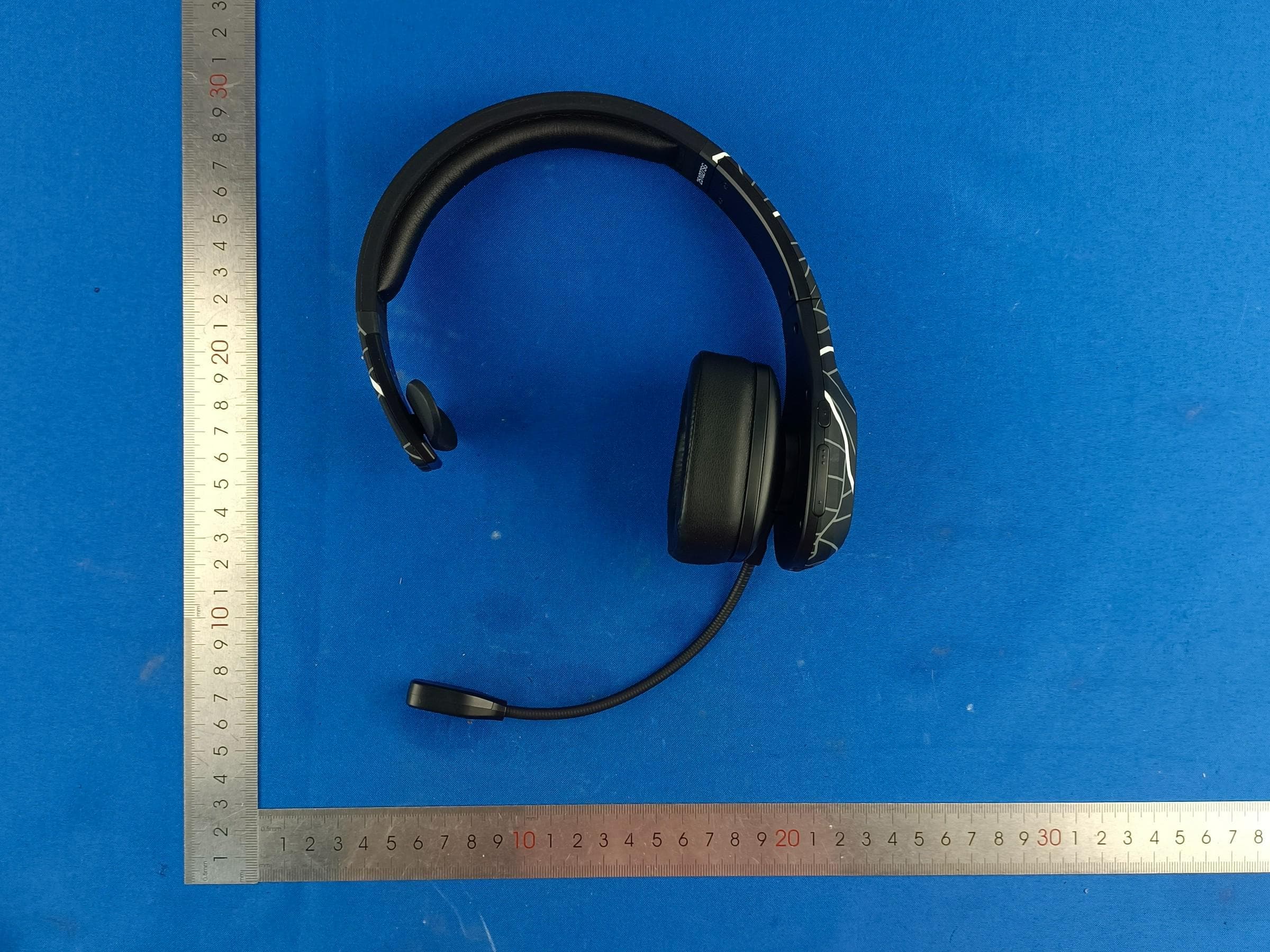
Report No.: AGC13051221002AP02 Page 1 of 3 EXTERNAL PHOTOS TOP VIEW OF EUT BOTTOM VIEW OF EUT Report No.: AGC13051221002AP02 Page 2 of 3 FRONT VIEW OF EUT BACK VIEW OF EUT Report No.: AGC13051221002AP02 Page 3 of 3 LEFT VIEW OF EUT RIGHT VIEW OF EUT ****************************************End of Report****************************************
ID Label/Location Info
FCC ID and IC Label Location 15mm*5mm FCC ID: 2ASKG-ULTIMATE IC: 24787-ULTIMATE HVIN: Elite Plus Ultimate
Internal Photos
Report No.: AGC13051221002AP02 Page 1 of 4 INTERNAL PHOTOS VIEW OF EUT(PORT) OPEN VIEW OF EUT Report No.: AGC13051221002AP02 Page 2 of 4 VIEW OF BATTERY INTERNAL VIEW OF EUT-1 BT Antenna Report No.: AGC13051221002AP02 Page 3 of 4 INTERNAL VIEW OF EUT-2 INTERNAL VIEW OF EUT-3 Report No.: AGC13051221002AP02 Page 4 of 4 INTERNAL VIEW OF EUT-4 ****************************************End of Report****************************************
RF Exposure Info
RF EXPOSURE EVALUATION 1. PRODUCT INFORMATION Product Description Bluetooth Headset Model Name Elite Plus Ultimate FCC ID 2ASKG-ULTIMATE 2. EVALUATION METHOD According to 447498 D01 General RF Exposure Guidance v06 The 1-g and 10-g SAR test exclusion thresholds for 100 MHz to 6 GHz at test separation distances ≤ 50 mm are determined by: [(max. power of channel, including tune-up tolerance, mW)/(min. test separation distance, mm)] ·[√f(GHz)] ≤ 3.0 for 1-g SAR and ≤ 7.5 for 10-g extremity SAR. Where f(GHz) is the RF channel transmit frequency in GHz Power and distance are rounded to the nearest mW and mm before calculation 3. CALCULATION BR&EDR: P t =1.494dBm=1.41mW The value of the Maximum output power P t is referred to the test report of the CFR47 §15.247. The result for RF exposure evaluation SAR=(1.41mW / 5mm).[√2.480GHz)]=0.443<3.0 for 1-g SAR and ≤ 7.5 for 10-g extremity SAR. 4. CONCLUSION The SAR evaluation is not required.
Test Report
AntennaSpecific Model:KH10H Manufacturer SKYWINGCommunicationElectronicsCo.,Ltd address No.62,10Rd,Longyan,HumenTown,DongguanCity, GuangdongProvince ProductType:MeanderLinePCBAntenna Technicalparameter ElectronicParameter FrequencyRange2400~2500MHz Inputimpedance50Ω VSWR≤2 GainMax1.8dBi PhysicalParameter MaterialPCB/Cu Operationtemperature-30°C~+80°C Storetemperature-30°C~+80°C AntennaSpecification TestResult: AntennaSpecifications FrequencyVNAETotal.dB(dB)Efficiency 2400MHz0.69399141.07% 2410MHz1.1433847.24% 2420MHz0.22305240.48% 2430MHz-0.1365933.93% 2440MHz0.3532637.82% 2450MHz0.93989442.77% 2460MHz1.7983852.67% 2470MHz0.64980941.93% 2480MHz-0.21593335.66% 2490MHz-0.47663934.62% 2500MHz0.71074140.22% Direction:
Test Report
Page 1 of 65 FCC Test Report Report No.: AGC13051221002FE03 FCC ID : 2ASKG-ULTIMATE APPLICATION PURPOSE : Original Equipment PRODUCT DESIGNATION : Bluetooth Headset BRAND NAME : Blue Tiger MODEL NAME : Elite Plus Ultimate APPLICANT : North American Blue Tiger Company, LLC DATE OF ISSUE : Nov. 03, 2022 STANDARD(S) : FCC Part 15.247 REPORT VERSION : V1.0 Attestation of Global Compliance (Shenzhen) Co., Ltd Report No.: AGC13051221002FE03 Page 2 of 65 REPORT REVISE RECORD Report Version Revise Time Issued Date Valid Version Notes V1.0 / Nov. 03, 2022 Valid Initial Release Report No.: AGC13051221002FE03 Page 3 of 65 TABLE OF CONTENTS 1. VERIFICATION OF CONFORMITY .................................................................................................................. 5 2. GENERAL INFORMATION .............................................................................................................................. 6 2.1. PRODUCT DESCRIPTION ........................................................................................................................ 6 2.2. TABLE OF CARRIER FREQUENCYS ....................................................................................................... 6 2.3. RECEIVER INPUT BANDWIDTH .............................................................................................................. 7 2.4. EXAMPLE OF A HOPPING SEQUENCY IN DATA MODE ......................................................................... 7 2.5. EQUALLY AVERAGE USE OF FREQUENCIES AND BEHAVIOUR ......................................................... 7 2.6. RELATED SUBMITTAL(S) / GRANT (S) .................................................................................................... 8 2.7. TEST METHODOLOGY ............................................................................................................................. 8 2.8. SPECIAL ACCESSORIES ......................................................................................................................... 8 2.9. EQUIPMENT MODIFICATIONS ................................................................................................................. 8 2.10. ANTENNA REQUIREMENT..................................................................................................................... 8 3. MEASUREMENT UNCERTAINTY ................................................................................................................... 9 4. DESCRIPTION OF TEST MODES ................................................................................................................. 10 5. SYSTEM TEST CONFIGURATION ................................................................................................................ 11 5.1. CONFIGURATION OF EUT SYSTEM ...................................................................................................... 11 5.2. EQUIPMENT USED IN TESTED SYSTEM .............................................................................................. 11 5.3. SUMMARY OF TEST RESULTS .............................................................................................................. 11 6. TEST FACILITY .............................................................................................................................................. 12 7. PEAK OUTPUT POWER ................................................................................................................................ 13 7.1. MEASUREMENT PROCEDURE ............................................................................................................. 13 7.2. TEST SET-UP (BLOCK DIAGRAM OF CONFIGURATION) .................................................................... 13 7.3. LIMITS AND MEASUREMENT RESULT .................................................................................................. 14 8. 20DB BANDWIDTH ........................................................................................................................................ 19 8.1. MEASUREMENT PROCEDURE ............................................................................................................. 19 8.2. TEST SET-UP (BLOCK DIAGRAM OF CONFIGURATION) .................................................................... 19 8.3. LIMITS AND MEASUREMENT RESULTS ............................................................................................... 20 9. CONDUCTED SPURIOUS EMISSION........................................................................................................... 25 9.1. MEASUREMENT PROCEDURE ............................................................................................................. 25 Report No.: AGC13051221002FE03 Page 4 of 65 9.2. TEST SET-UP (BLOCK DIAGRAM OF CONFIGURATION) .................................................................... 25 9.3. MEASUREMENT EQUIPMENT USED .................................................................................................... 25 9.4. LIMITS AND MEASUREMENT RESULT .................................................................................................. 25 10. RADIATED EMISSION ................................................................................................................................. 46 10.1. MEASUREMENT PROCEDURE ........................................................................................................... 46 10.2. TEST SETUP ......................................................................................................................................... 48 10.3. LIMITS AND MEASUREMENT RESULT ............................................................................................... 49 10.4. TEST RESULT........................................................................................................................................ 49 11. NUMBER OF HOPPING FREQUENCY ...............................................…
Text truncated - open the document above for the full version.
Test Report
Report No.: AGC13051221002FE03 Page 60 of 65 12. TIME OF OCCUPANCY (DWELL TIME) 12.1. MEASUREMENT PROCEDURE The EUT shall have its hopping function enabled. Use the following spectrum analyzer settings: 1. Span: Zero span, centered on a hopping channel. 2. RBW shall be≤channel spacing and where possible RBW should be set >> 1 / T, where T is the expected dwell time per channel. 3. Sweep: As necessary to capture the entire dwell time per hopping channel; where possible use a video trigger and trigger delay so that the transmitted signal starts a little to the right of the start of the plot. The trigger level might need slight adjustment to prevent triggering when the system hops on an adjacent channel; a second plot might be needed with a longer sweep time to show two successive hops on a channel. 4. Detector function: Peak. Trace: Max hold. 5. Use the marker-delta function to determine the transmit time per hop. 6. Repeat the measurement using a longer sweep time to determine the number of hops over the period specified in the requirements. The sweep time shall be equal to, or less than, the period specified in the requirements. Determine the number of hops over the sweep time and calculate the total number of hops in the period specified in the requirements, using the following equation: (Number of hops in the period specified in the requirements) = (number of hops on spectrum analyzer) × (period specified in the requirements / analyzer sweep time) 7. The average time of occupancy is calculated from the transmit time per hop multiplied by the number of hops in the period specified in the requirements. 12.2. TEST SETUP (BLOCK DIAGRAM OF CONFIGURATION) Same as described in section 8.2 12.3. MEASUREMENT EQUIPMENT USED The same as described in section 6 12.4. LIMITS AND MEASUREMENT RESULT Test Data of Dwell Time Channel Time of Pulse for DH5 (ms) Number of hops in the period specified in the requirements Sweep Time (ms) Limit (ms) Pass or Fail 2402 2.866 24.0*4 275.136 400 Pass 2441 2.866 24.0*4 275.136 400 Pass 2480 2.866 22.0*4 252.208 400 Pass Note: The GFSK modulation is the worst case and recorded in the report. Report No.: AGC13051221002FE03 Page 61 of 65 Test Graphs of Dwell Time Test_Graph_BR_HOP_ANT1_NA_1Mbps_2402_Number of Busrt Test_Graph_BR_HOP_ANT1_NA_1Mbps_2402_Time per Burst Report No.: AGC13051221002FE03 Page 62 of 65 Test_Graph_BR_HOP_ANT1_NA_1Mbps_2441_Number of Busrt Test_Graph_BR_HOP_ANT1_NA_1Mbps_2441_Time per Burst Report No.: AGC13051221002FE03 Page 63 of 65 Test_Graph_BR_HOP_ANT1_NA_1Mbps_2480_Number of Busrt Test_Graph_BR_HOP_ANT1_NA_1Mbps_2480_Time per Burst Report No.: AGC13051221002FE03 Page 64 of 65 13. FREQUENCY SEPARATION 13.1. MEASUREMENT PROCEDURE The EUT shall have its hopping function enabled. Use the following spectrum analyzer settings: 1. Span: Wide enough to capture the peaks of two adjacent channels. 2. RBW: Start with the RBW set to approximately 30% of the channel spacing; adjust as necessary to best identify the center of each individual channel. 3. Video (or average) bandwidth (VBW) ≥ RBW. 4. Sweep: Auto. e) Detector function: Peak. f) Trace: Max hold. g) Allow the trace to stabilize. Use the marker-delta function to determine the separation between the peaks of the adjacent channels. 13.2. TEST SETUP (BLOCK DIAGRAM OF CONFIGURATION) Same as described in section 6.2 13.3. MEASUREMENT EQUIPMENT USED The same as described in section 6.3 13.4. LIMITS AND MEASUREMENT RESULT Test Data of Frequency Separation Test Mode Channel Separation (MHz) Limits Pass or Fail GFSK Hopping 1.029 >= 2/3 -20dB BW Pass Test Graphs of Number of Hopping Frequency Test_Graph_BR_HOP_ANT1_NA_1Mbps_Hopping Separation Note: The GFSK modulation is the worst case and recorded in the report. Report No.: AGC13051221002FE03 Page 65 of 65 APPENDIX A: PHOTOGRAPHS OF TEST SETUP Refer to the Report No.: AGC13051221002AP01 APPENDIX B: PHOTOGRAPHS OF EUT Refer to the Report No.: AGC13051221002AP02 ----END OF REPORT---- Conditions of Issuance of Test Reports 1. All samples and goods are accepted by the Attestation of Global Compliance (Shenzhen) Co., Ltd. (the “Company”) solely for testing and reporting in accordance with the following terms and conditions. The company provides its services on the basis that such terms and conditions constitute express agreement between the company and any person, firm or company requesting its services (the “Clients”). 2. Any report issued by Company as a result of this application for testing services (the “Report”) shall be issued in confidence to the Clients and the Report will be strictly treated as such by the Company. It may not be reproduced either in its entirety or in part and it may not be used for advertising or other unauthorized purposes without the written consent of the Company. The Clients to whom the Report is issued may, however, show or send it, or a certified copy thereof prepared by the Company to its customer, supplier or other persons directly concerned. The Company will not, without the consent of the Clients, enter into any discussion or correspondence with any third party concerning the contents of the Report, unless required by the relevant governmental authorities, laws or court orders. 3.The Company shall not be called or be liable to be called to give evidence or testimony on the Report in a court of law without its prior written consent, unless required by the relevant governmental authorities, laws or court orders. 4. In the event of the improper use of the report as determined by the Company, the Company reserves the right to withdraw it, and to adopt any other additional remedies which may be appropriate. 5. Samples submitted for testing are accepted on the understanding that the Report issued cannot form the basis of, or be the instrument for, any legal action against the Company. 6. The Company will not be liable for or accept responsibility for any loss or damage however arising from the use of information contained i…
Text truncated - open the document above for the full version.
Test Setup Photos
Report No.: AGC13051221002AP01 Page 1 of 2 TEST SETUP PHOTOS RADIATED EMISSION TEST SETUP BELOW 1GHz RADIATED EMISSION TEST SETUP ABOVE 1GHz Report No.: AGC13051221002AP01 Page 2 of 2 RF CONDUCTED TEST SETUP ****************************************End of Report*************************************
Contact Information
Applicant
Joel Raney(CEO)
Technical Contact
Test Firm
Attestation of Global Compliance (Shenzhen) Co., LDoris Li
[email protected]+86-755-25234088
Technical Specifications
| # | Rule Parts | Frequency Range | Power Output |
|---|---|---|---|
| 1 | 15C | 2.40 GHz - 2.48 GHz | 1.40 mW |
Other Applications from Raneys LLC d/b/a Blue Tiger USA
2ASKG-STORMP
Feb 10, 2026Bluetooth Headset
Equipment Class
DSS - Part 15 Spread Spectrum Transmitter