2ASLJRT800Scanning Receiver
RHOTHETA International Inc.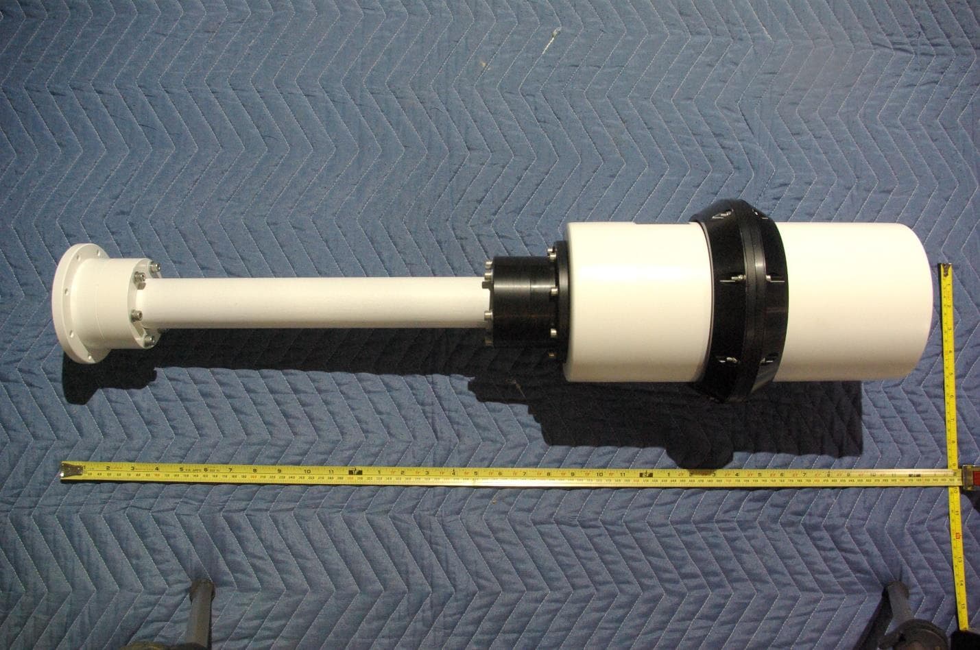
Click to zoom
Application Details
- Equipment Class
- CSR - Scanning Receiver
- Date of Grant
- Jan 29, 2020
- Application Purpose
- Original Equipment
- Date of Application
- Jan 29, 2020
- Equipment Note
- Scanning Receiver
- Frequency Range
- 406.10000000 - 470.00000000
- Company
- RHOTHETA International Inc.
- Country
- United States
Documents & Files
Document Text
Text extracted from the exhibit documents filed with the FCC. Open a document above to read the original.
Users Manual
User Manual R R T T - - 8 8 0 0 0 0 Wideband Precision Direction Finder RHOTHETA Elektronik GmbH RHOTHETA User Manual RT-800 Page 2 of 78 Edited by: RHOTHETA Elektronik GmbH Kemmelpark Dr.-Ingeborg-Haeckel-Str. 2 82418 Murnau Germany Tel.: +49 8841 4879 - 0 Fax: +49 8841 4879 - 15 Internet: www.rhotheta.de E-Mail: [email protected] Copyright © RHOTHETA Elektronik GmbH All rights reserved - Issue: 2020/01/09 [Rev 2.02] - Document-ID: 12-9-1-0003-3-1-61 NOTE: The manufacturer reserve the right to make modifications at any time and without previous information of the here described product. RHOTHETA User Manual RT-800 Page 3 of 78 RHOTHETA User Manual RT-800 Page 4 of 78 Content 1 Safety Instructions .......................................................................................................... 8 1.1 Legend of Symbols ................................................................................................................................. 8 1.2 Basic Safety Instructions ........................................................................................................................ 9 2 Legal Information ............................................................................................................. 9 2.1 EU Declaration of Conformity ................................................................................................................. 9 2.2 Legal Limitations of Use within the EU ................................................................................................... 9 2.3 FCC Information (USA)......................................................................................................................... 10 2.4 ISED Information (Canada) .................................................................................................................. 10 3 Use and Characteristics ................................................................................................ 11 4 Short Description ........................................................................................................... 12 4.1 Front View (DCU) ................................................................................................................................. 12 4.2 Front View (Buttons and Display) ......................................................................................................... 13 4.3 Bearing Display (Main Page) ................................................................................................................ 15 4.4 Rear View ............................................................................................................................................. 18 5 Operation ........................................................................................................................ 19 5.1 Bearing Operation ................................................................................................................................. 19 5.1.1 Instruction Fields (flags, errors and warnings) ......................................................................... 21 5.1.2 Alarm Function ......................................................................................................................... 22 5.1.3 Function Repeat ...................................................................................................................... 22 5.1.4 Function Clear.......................................................................................................................... 22 5.1.5 Function Channel 16 ................................................................................................................ 23 5.1.6 Function SAR ........................................................................................................................... 23 5.1.7 Function Scan .......................................................................................................................... 23 5.2 Monitoring Operation ............................................................................................................................ 24 5.2.1 Timing of normal Monitoring Operation ................................................................................... 25 5.2.2 Timing Monitoring with selected Cospas-Sarsat Main Frequency .......................................... 25 5.2.3 Monitoring operation with filtering of Emergency Transmitters: ID-Only ................................. 25 5.3 Standby-Operation................................................................................................................................ 26 5.3.1 Standby Mode SAR ................................................................................................................. 26 5.3.2 Standby Mode PLB .................................................................................................................. 26 5.4 Scan-Dialogue ...................................................................................................................................... 27 5.4.1 Fast Channel Scan .................................................................................................................. 27 5.4.2 Fast Marine Scan ..................................................................................................................... 28 5.5 SAR-Dialogue ....................................................................................................................................... 30 5.6 Cospas-Sarsat Decoding Data Content ............................................................................................... 31 6 Operating and Adjusting ............................................................................................... 33 6.1 Reset of the DCU .................................................................................................................................. 34 6.2 Setting Main Bearing Frequency/…
Text truncated - open the document above for the full version.
Attestation Statements
RHOTHETA Elektronik GmbH Dr.-Ingeborg-Haeckel-Str. 2 82418 Murnau Germany Tel.: +49 8841 4879 - 0 E-Mail: [email protected] Fax: +49 8841 4879 - 15 Internet: www.rhotheta.de 12-9-4-5-00007-60 47CFR §15.121 Compliance [Rev 1.00] Vervielfältigung und Weitergabe nur mit ausdrücklicher schriftlicher Genehmigung durch RHOTHETA – Copying and disclosure only with explicit written permission by RHOTHETA Page 1 of 1 47CFR §15.121 Compliance Statement 1 Coverage This statement is valid for RHOTHETA receiver models designed in compliance to 47CFR Part 15 §15.121, applying the same technological means of compliance, independent of their use in systems to be certified for marketing in the United States of America. Systems where these receivers are used are: • RT-400 • RT-500-M • RT-600 A • RT-600 L • RT-600 Light • RT-800 • RT-1000 A • RT-1000 C • RT-1000 Multichannel 2 Compliance Statement The equipment under application herein incorporates a scanning receiver, so 47CFR §15.121 applies. The equipment is incapable of operating (tuning) or being readily altered by the operator to operate within the frequency bands allocated to cellular radiotelephone service frequency bands (824 to 849 and 869 to 894 MHz). The equipment is also incapable of converting digital cellular transmissions to analog voice audio. Multi-stage frontend filters in SMD technology, including low-pass filters, high-pass filters and varactor-tuned band-pass filters under microcontroller control and with limited electrical tuning range cannot be altered to enable the receiver to scan the cellular radiotelephone service bands, especially not by means of clipping the leads of or installing diodes, resistors, jumpers or wires, or other simple component. The local oscillator circuitry, including low-pass filters, is under microcontroller control and cannot be altered to enable the receiver to scan the cellular radiotelephone service bands, especially not by means of clipping the leads of or installing diodes, resistors, jumpers or wires, or other simple component. Basic rejection of the cellular radiotelephone service bands by input filters is beyond the required measure of 38 dB (typical >80 dB for both filter stages). This is ensured by the physical design of filters. No plug-in semiconductor chips can be replaced, since no such chips are used. User entrance of receive frequencies in cellular radiotelephone service frequency bands is rejected by the firmware. No means are incorporated in the firmware to calculate internal receiver settings (filter, oscillator, etc.) for receive frequencies in the cellular radiotelephone service frequency bands. The microprocessor information is not accessible to the user. Without knowledge of processor information and circuitry, any attempt to modify the circuitry would render the equipment inoperable. Measurements according to industrial standards for AM and FM voice communication equipment under application of the 12 dB SINAD criteria with standard modulation (30% AM, 1 kHz and 3 kHz FM deviation, 1 kHz tone) as well as additional signal strength indication based measurement show spurious response rejections above 100 dB within cellular radiotelephone service frequency bands. In view of the above, the receiver complies with §15.121 of the Commission rules.
Cover Letter(s)
Page 1 of 2 January 30, 2020 Timco Engineering Inc. 849 NW State Road 45 Newberry, FL 32669 Applicant: RHOTHETA International Inc. 8201 Peters Road, Suite 1000 Fort Lauderdale, FL 33324 Re: Confidentiality for submittal information regarding FCC ID: 2ASLJRT800 Product: Scanning Receiver operated under 47CFR paragraph 15B Dear Sirs: RHOTHETA International Inc. requests that the material in the Block Diagram, Operational Description, Schematics, Internal Photographs, and Tune Up Procedure be withheld from public disclosure pursuant to Sections 0.457 and 0.459 of the Commission’s Rules following grant of the application. In support of this request, RHOTHETA International Inc. submits the following information. CONFIDENTIAL FILES RT800Conf BlkDia.pdf RT800Conf OpDes.pdf RT800Conf Schem.pdf RT800Conf TunPro.pdf RT800Conf IntPho.pdf 1. Identification of the specific information for which confidential treatment is sought: The materials set forth in the Block Diagram, Operational Description, Schematics, Internal Photographs, and Tune Up Procedure which are segregated, from the non-confidential exhibits of the application, are those for which confidentiality is sought. 2. Identification of the Commission proceeding in which the information was submitted or a description of the circumstances giving rise to the submission: The proceeding is that involving the application for equipment authorization (certification) under FCC ID: 2ASLJRT800 3. Explanation of the degree to which the information is commercial or financial, or contains a trade secret or is privileged: This material includes Block Diagram, Operational Description, Schematics, and Tune Up Procedure. As such, this material is treated as highly confidential business information. ROGERS LABS, INC. 4405 West 259 th Terrace Louisburg, KS 66053 913 837-3214 Page 2 of 2 4. Explanation of the degree to which the information concerns a service that is subject to competition: The material for which confidentiality is sought is employed in the design and manufacture of this transmitting equipment that is offered on a highly competitive basis. Customers for this equipment have a variety of competing sources. 5. Explanation of how disclosure of the information could result in substantial competitive harm: Disclosure would, in effect, give away the fruits of the labors of RHOTHETA International Inc.’s engineering personnel, who have designed the equipment and the manufacturing process. Disclosure would also offer competitors additional unwarranted insight into the state of the product development, thereby allowing competitors an advantage, not available to RHOTHETA International Inc. 6. Identification of any measures taken by the submitting party to prevent unauthorized disclosure: The information for which confidential treatment is sought is kept confidential by RHOTHETA International Inc. and not made available to third parties except pursuant to non-disclosure agreements. 7. Identification of whether the information is available to the public and the extent of any previous disclosure of the information to third parties: To the knowledge of those preparing this application, the information has not been disclosed publicly heretofore. While the general theory of operation of this equipment has been the subject of numerous disclosures in industry and standards groups as well as in rule making proceedings of the FCC, the protection sought is narrowly drawn and pertains to certain specific implementations of this radio technology. 8. Justification of the period during which the submitting party asserts that the material should not be available for public disclosure: This material should not be disclosed for at least 25 years. While improvements in design are made relatively frequently, disclosure of the design information would lead to insights into both design and manufacturing techniques that could have an adverse competitive effect for many years to come. As such, it is important that the design not be made available to unauthorized persons who might attempt to use knowledge of the design to compromise the applications for which the equipment will be employed. Should you require any further information, please contact the undersigned. Thank you for your consideration in this matter. Sincerely, Scot Rogers
External Photos
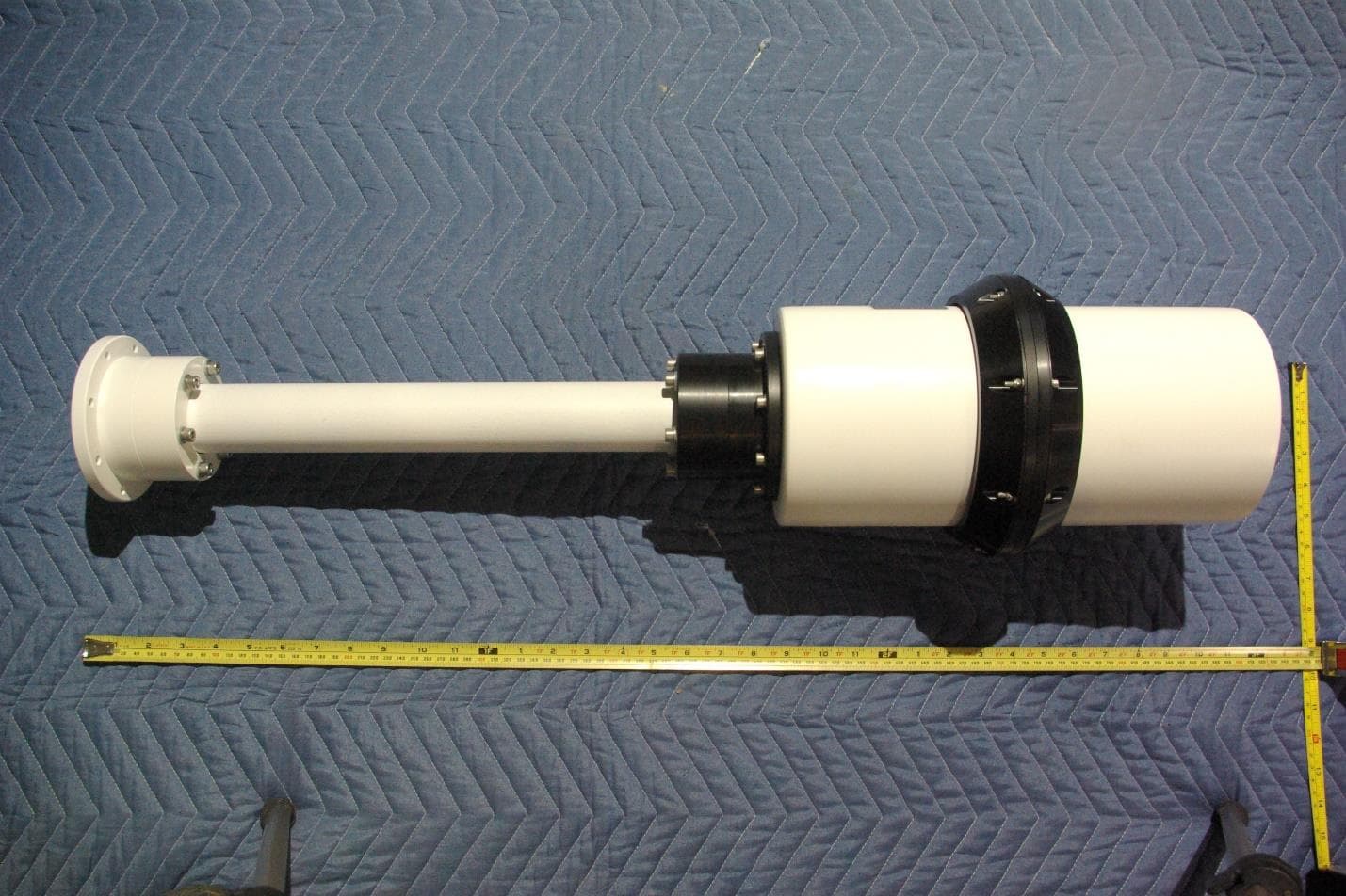
Rogers Labs, Inc. RHOTHETA International Inc. S/N: 00781 4405 W. 259th Terrace Model: RT-800 FCC ID: 2ASLJRT800 Louisburg, KS 66053 Test: 190211B IC: 24836-RT800 Phone/Fax: (913) 837-3214 Test to: CFR47 15, RSS-210, RSS-135 Date: January 30, 2020 Revision 1 File: RT800 ExtPho Page 1 of 4 External photographs of equipment under test (EUT - Antenna Unit (AU)) Rogers Labs, Inc. RHOTHETA International Inc. S/N: 00781 4405 W. 259th Terrace Model: RT-800 FCC ID: 2ASLJRT800 Louisburg, KS 66053 Test: 190211B IC: 24836-RT800 Phone/Fax: (913) 837-3214 Test to: CFR47 15, RSS-210, RSS-135 Date: January 30, 2020 Revision 1 File: RT800 ExtPho Page 2 of 4 Rogers Labs, Inc. RHOTHETA International Inc. S/N: 00781 4405 W. 259th Terrace Model: RT-800 FCC ID: 2ASLJRT800 Louisburg, KS 66053 Test: 190211B IC: 24836-RT800 Phone/Fax: (913) 837-3214 Test to: CFR47 15, RSS-210, RSS-135 Date: January 30, 2020 Revision 1 File: RT800 ExtPho Page 3 of 4 Rogers Labs, Inc. RHOTHETA International Inc. S/N: 00781 4405 W. 259th Terrace Model: RT-800 FCC ID: 2ASLJRT800 Louisburg, KS 66053 Test: 190211B IC: 24836-RT800 Phone/Fax: (913) 837-3214 Test to: CFR47 15, RSS-210, RSS-135 Date: January 30, 2020 Revision 1 File: RT800 ExtPho Page 4 of 4 Accessary (Display Control Unit (DCU))
ID Label/Location Info
Rogers Labs, Inc. RHOTHETA International Inc. S/N: 00781 4405 W. 259th Terrace Model: RT-800 FCC ID: 2ASLJRT800 Louisburg, KS 66053 Test: 190211B IC: 24836-RT800 Phone/Fax: (913) 837-3214 Test to: CFR47 15, RSS-135 Date: January 16, 2020 Revision 1 File: RT800 LabelSmpl Page 1 of 2 Label Sample and Placement LABEL Rogers Labs, Inc. RHOTHETA International Inc. S/N: 00781 4405 W. 259th Terrace Model: RT-800 FCC ID: 2ASLJRT800 Louisburg, KS 66053 Test: 190211B IC: 24836-RT800 Phone/Fax: (913) 837-3214 Test to: CFR47 15, RSS-135 Date: January 16, 2020 Revision 1 File: RT800 LabelSmpl Page 2 of 2
Test Report
Testing NVLAP Lab Code 200087-0 Rogers Labs, Inc. RHOTHETA International Inc. S/N: 00781 4405 W. 259th Terrace Model: RT-800 FCC ID: 2ASLJRT800 Louisburg, KS 66053 Test: 190211AB IC: 24836-RT800 Phone/Fax: (913) 837-3214 Test to: 47CFR, 15(b), RSS-135 Date: January 30, 2020 Revision 1 File: Rhotheta RT800 TstRpt 190211B Page 1 of 24 Engineering Test Report for Grant of Certification Application 47CFR, Part 15B 15.109, 15.111, & 15.121 Industry Canada RSS-135 Issue 2 Model: RT-800 Scanning Receiver 118-470 MHz FCC ID: 2ASLJRT800 IC: 24836-RT800 RHOTHETA International Inc. 8201 Peters Road, Suite 1000 Fort Lauderdale, FL 33324 FCC Designation: US5305 IC Test Site Registration: 3041A-1 Test Report Number: 190211B Test Date: February 11, 2019 Authorized Signatory: Scot D. Rogers Rogers Labs, Inc. 4405 West 259 th Terrace Louisburg, KS 66053 Telephone/Facsimile: (913) 837-3214 This report shall not be reproduced except in full, without the written approval of the laboratory. This report must not be used by the client to claim product certification, approval, or endorsement by NVLAP, NIST, or any agency of the U.S. Government. ROGERS LABS, INC. 4405 West 259 th Terrace Louisburg, KS 66053 Phone / Fax (913) 837-3214 Testing NVLAP Lab Code 200087-0 Rogers Labs, Inc. RHOTHETA International Inc. S/N: 00781 4405 W. 259th Terrace Model: RT-800 FCC ID: 2ASLJRT800 Louisburg, KS 66053 Test: 190211AB IC: 24836-RT800 Phone/Fax: (913) 837-3214 Test to: 47CFR, 15(b), RSS-135 Date: January 30, 2020 Revision 1 File: Rhotheta RT800 TstRpt 190211B Page 2 of 24 Tabl e of Cont ents Table of Contents TABLE OF CONTENTS .................................................................................................. 2 REVISIONS ..................................................................................................................... 3 FOREWORD ................................................................................................................... 4 OPINION / INTERPRETATION OF RESULTS ............................................................... 4 EQUIPMENT TESTED, FUNCTION, AND CONFIGURATION ...................................... 4 Equipment Tested ................................................................................................................................................ 4 Equipment Function ............................................................................................................................................ 5 Equipment Configuration.................................................................................................................................... 6 APPLICANT COMPANY INFORMATION ...................................................................... 7 EQUIPMENT INFORMATION ......................................................................................... 7 Product Details ..................................................................................................................................................... 7 APPLICATION FOR CERTIFICATION, 47CFR 2.1033 (B) ............................................ 8 APPLICABLE STANDARDS & TEST PROCEDURES .................................................. 9 STATEMENT OF MODIFICATIONS AND DEVIATIONS ............................................... 9 EQUIPMENT TESTING PROCEDURES ........................................................................ 9 AC Line Conducted Emission Test Procedure .................................................................................................. 9 Radiated Emission Test Procedure ..................................................................................................................... 9 Diagram 1 Test arrangement for Radiated emissions ........................................................................................ 10 Diagram 2 Test arrangement for Radiated emissions tested on Open Area Test Site (OATS) .......................... 11 TEST SITE LOCATIONS .............................................................................................. 12 UNITS OF MEASUREMENTS ...................................................................................... 12 ENVIRONMENTAL CONDITIONS................................................................................ 12 LIST OF TEST EQUIPMENT ........................................................................................ 13 Testing NVLAP Lab Code 200087-0 Rogers Labs, Inc. RHOTHETA International Inc. S/N: 00781 4405 W. 259th Terrace Model: RT-800 FCC ID: 2ASLJRT800 Louisburg, KS 66053 Test: 190211AB IC: 24836-RT800 Phone/Fax: (913) 837-3214 Test to: 47CFR, 15(b), RSS-135 Date: January 30, 2020 Revision 1 File: Rhotheta RT800 TstRpt 190211B Page 3 of 24 EMISSION MEASUREMENTS ..................................................................................... 14 AC Line Conducted EMI Procedure ................................................................................................................ 14 Radiated EMI Procedure................................................................................................................................... 14 Figure 1 Radiated Emissions Plot emissions Taken in Screen Room ................................................................ 15 Figure 2 Radiated Emissions Plot emissions Taken in Screen Room ................................................................ 16 Figure 3 Radiated Emissions Plot emissions Taken in Screen Room ................................................................ 17 Figure 4 Radiated Emissions Plot emissions Taken in Screen Room ................................................................ 18 Emissions Test Data ........................................................................................................................................... 19 Table 1 Radiated Emissions Data from EUT test configuration .......................................................................…
Text truncated - open the document above for the full version.
Test Setup Photos
Rogers Labs, Inc. RHOTHETA International Inc. S/N: 00781 4405 W. 259th Terrace Model: RT-800 FCC ID: 2ASLJRT800 Louisburg, KS 66053 Test: 190211B IC: 24836-RT800 Phone/Fax: (913) 837-3214 Test to: CFR47 15, RSS-210, RSS-135 Date: January 30, 2020 Revision 1 File: RT800 TSup Page 1 of 2 Test setup photographs Rogers Labs, Inc. RHOTHETA International Inc. S/N: 00781 4405 W. 259th Terrace Model: RT-800 FCC ID: 2ASLJRT800 Louisburg, KS 66053 Test: 190211B IC: 24836-RT800 Phone/Fax: (913) 837-3214 Test to: CFR47 15, RSS-210, RSS-135 Date: January 30, 2020 Revision 1 File: RT800 TSup Page 2 of 2
Contact Information
Applicant
Alex Collantes
Test Firm
Rogers Labs, Inc.Scot Rogers
Technical Specifications
| # | Rule Parts | Frequency Range | Power Output |
|---|---|---|---|
| 5 | 15B | 406.1 MHz - 470 MHz | - |
Other Applications from RHOTHETA International Inc.
2ASLJRT400
Feb 11, 2020Scanning Receiver
Equipment Class
CSR - Scanning Receiver