2ASM6-CXWAWireless Controller
Conductix-Wampfler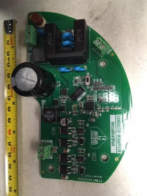
Click to zoom
Application Details
- Equipment Class
- DXX - Part 15 Low Power Communication Device Transmitter
- Date of Grant
- Jan 11, 2021
- Application Purpose
- Original Equipment
- Date of Application
- Jan 11, 2021
- Equipment Note
- Wireless Controller
- Frequency Range
- 2402.00000000 - 2480.00000000
- Company
- Conductix-Wampfler
- Country
- United States
Documents & Files
Document Text
Text extracted from the exhibit documents filed with the FCC. Open a document above to read the original.
Users Manual
Supplemental User’s Manual INTEGRATION INSTRUCTIONS per FCC KDB 996369 D03, Section 2.0 2.2 List of applicable FCC rules The module has been certified for use under FCC Part 15.249 only 2.3 Summarize the specific operational use conditions The host device must be tested for spurious emissions due to the module’s lack of its own shielding. 2.4 Limited module procedures The host device must be tested for spurious emissions due to the module’s lack of its own shielding. 2.5 Trace antenna designs Antenna is integrated into module and the module should be used with no other antennas 2.6 RF exposure considerations Device is inherently compliant with RF exposure requirements since it meets 15.249 requirements 2.7 Antennas Antenna is integrated into module and the module should be used with no other antennas 2.8 Label and compliance information Module contains its own label 2.9 Information on test modes and additional testing requirements None required. 2.10 Additional testing, Part 15 Subpart B disclaimer This module has been tested and certified to comply with FCC Part 15C requirements. The host device to which it is installed may require additional testing to show compliance with FCC Part 15B requirements. Supplemental User’s Manual INTEGRATION INSTRUCTIONS per FCC KDB 996369 D03, Section 2.0 Notice: OEM should include the following warnings on the label: “Contains FCC ID: 2ASM6-CXWA, IC:11769A-CXWA” As well as the model name: “VersaReel Blue” Installer should include the following in the user’s manual: “This device complies with part 15 of the FCC Rules. Operation is subject to the following two conditions: (1) This device may not cause harmful interference, and (2) this device must accept any interference received, including interference that may cause undesired operation.” “Changes of modification not expressly approved by the party responsible for compliance could void the user’s authority to operate the equipment.”
Users Manual
VERSAREEL BLUE USER MODULE MANUAL XA-587112 | 11.13.19 www.conductix.us VersaReel ® Blue User Module Manual VERSAREEL BLUE MANUAL XA-587112 | 11.13.19 2 The technical data and images which appear in this manual are for informational purposes only. NO WARRANTIES, EXPRESS OR IMPLIED, INCLUDING WARRANTIES OF MERCHANTABILITY OR FITNESS FOR A PARTICULAR PURPOSE, ARE CREATED BY THE DESCRIPTIONS AND DEPICTIONS OF THE PRODUCTS SHOWN IN THIS MANUAL. Conductix makes no warranty (and assumes no liability) as to function of equipment or operation of systems built according to customer design or of the ability of any of its products to interface, operate or function with any portions of customer systems not provided by Conductix. Seller agrees to repair or exchange the goods sold hereunder necessitated by reason of defective workmanship and material discovered and reported to Seller within one year after shipment of such goods to Buyer. Except where the nature of the defect is such that it is appropriate, in Seller’s judgment, to effect repairs on site, Seller’s obligation hereunder to remedy defects shall be limited to repairing or replacing (at Seller’s option) FOB point of original shipment by Seller, any part returned to Seller at the risk and cost of Buyer. Defective parts replaced by Seller shall become the property of Seller. Seller shall only be obligated to make such repair or replacement if the goods have been used by Buyer only in service recommended by Seller and altered only as authorized by Seller. Seller is not responsible for defects which arise from improper installation, neglect, or improper use or from normal wear and tear. Additionally, Seller’s obligation shall be limited by the manufacturer’s warranty (and is not further warranted by Seller) for all parts procured from others according to published data, specifications or performance information not designed by or for Seller. Seller further agrees to replace or at Seller’s option to provide a refund of the sales price of any goods that do not conform to applicable specifications or which differ from that agreed to be supplied which non-conformity is discovered and forthwith reported to Seller within thirty (30) days after shipment to the Buyer. Seller’s obligation to replace or refund the purchase price for non-conforming goods shall arise once Buyer returns such goods FOB point of original shipment by Seller at the risk and cost of Buyer. Goods replaced by Seller shall become the property of Seller. There is no guarantee or warranty as to anything made or sold by Seller, or any services performed, except as to title and freedom from encumbrances and, except as herein expressly stated and particularly, and without limiting the foregoing, there is no guarantee or warranty, express or implied, of merchantability or of fitness for any particular purpose or against claim of infringement or the like. Seller makes no warranty (and assumes no liability) as to function of equipment or operation of systems built to Buyer’s design or of the ability of any goods to interface, operate or function with any portions of Buyer’s system not provided by Seller. Seller’s liability on any claim, whether in contract, tort (including negligence), or otherwise, for any loss or damage arising out of, connected with, or resulting from the manufacture, sale, delivery, resale, repair, replacement or use of any products or services shall in no case exceed the price paid for the product or services or any part thereof which give rise to the claim. In no event shall Seller be liable for consequential, special, incidental or other damages, nor shall Seller be liable in respect of personal injury or damage to property not the subject matter hereof unless attributable to gross misconduct of Seller, which shall mean an act or omission by Seller demonstrating reckless disregard of the foreseeable consequences thereof. Seller is not responsible for incorrect choice of models or where products are used in excess of their rated and recommended capacities and design functions or under abnormal conditions. Seller assumes no liability for loss of time, damage or injuries to property or persons resulting from the use of Seller’s products. Buyer shall hold Seller harmless from all liability, claims, suits and expenses in connection with loss or damage resulting from operation of products or utilization of services, respectively, of Seller and shall defend any suit or action which might arise there from in Buyer’s name - provided that Seller shall have the right to elect to defend any such suit or action for the account of Buyer. The foregoing shall be the exclusive remedies of the Buyer and all persons and entitles claiming through the Buyer. CONDUCTIX INCORPORATED VERSAREEL BLUE MANUAL XA-587112 | 11.13.19 3 TABLE OF CONTENTS SECTION 1 - GETTING STARTED 4 Quick Guide 4 App Download 4 Device Safety Features 5 SECTION 2 - MOBILE APP INITIAL SETUP 6 Scan Screen 6 Info Screen 6 Scan Screen 7 Device List 7 Device Control 8 SECTION 3 - MOBILE APP USER CONFIGURATION 9 Default Pin Code Screen 9 Ready To Use Screen 9 Default Master Password Screen 10 Change Master Password Screen 11 Change Device Pincode Screen 11 Change Device Name 12 SECTION 4 - TROUBLESHOOTING APP 13 Incorrect Password Screen 15 Reel Damage Warning Screen 15 Attention: Changes or modifications not expressly approved by the manufacturer could void the user’s authority to operate this equipment. This product meets the applicable FCC Part 15 rules and Industry Canada’s license exempt RSSs. Operation is subject to the following two conditions: (1) this device may not cause interference, and (2) this device must accept any interference, including interference that may cause undesired operation of the device. Le présent materiel est conforme aux CNRexempts de licence d’Industrie Canada. Son fonctionnement est soumis aux deux conditions suivantes: (1) cet appareil ne peut pas provoquer d’interférences, et (2) cet ap…
Text truncated - open the document above for the full version.
Attestation Statements
Conductix-Wamplfer 10102 F. Street Omaha, NE 68127 402-339-9300 Date: November 25 th , 2020 To: Federal Communications Commission 45 L Street NE Washington, DC 20554 FCC ID:2ASM6-CXWA Integrated RF Module:Texas Instruments CC2640R2FRGZR wireless MCU To whom it may concern: This letter is to confirm that Conductix, Inc (d.b.a. Conductix-Wampfler) has integrated an FCC CFR47 Part 15compliant RF module into our host product, under the VersaReel Blue product family. Conductix has and will maintain complete control over all product integrations and installations. The final host product has been tested for spurious emissions and we have ensured that the data to the module is buffered in all applications. Should you have any questions or commented regarding this declaration, please contact us. Sincerely, Hau Tran Company:Conductix, Inc Address:10102 F Street, Omaha NE, 68138 Title:Director of Engineering, US CoE
Cover Letter(s)
Page 1 of 1 Request for Confidentiality Date: October 27, 2020 Subject: Confidentiality Request for: FCC ID: 2ASM6-CXWA IC: 11769A-CXWA Pursuant to FCC 47 CFR 0.457(d) and 0.459 and IC RSP-100, Section 9.4, the applicant requests that a part of the subject FCC application be held confidential. Type of Confidentiality Requested Exhibit ☐ Short Term ☒ Permanent ☐ Not Provided Block Diagrams ☐ Short Term ☐ Not Provided External Photos ☐ Short Term ☐ Permanent ☐ Not Provided Internal Photos ☐ Short Term ☒ Permanent ☐ Not Provided Operation Description/Theory of Operation ☐ Short Term ☐ Permanent ☒ Not Provided Parts List & Placement/BOM ☐ Short Term ☐ Permanent ☒ Not Provided Tune-Up Procedure ☐ Short Term ☒ Permanent ☐ Not Provided Schematics ☐ Short Term ☐ Not Provided Test Setup Photos ☐ Short Term ☐ Permanent ☐ Not Provided User’s Manual The above-mentioned company has spent substantial effort in developing this product and it is one of the first of its kind in industry. Having the subject information easily available to "competition" would negate the advantage they have achieved by developing this product. Not protecting the details of the design will result in financial hardship. Permanent Confidentiality: The applicant requests the exhibits listed above as permanently confidential be permanently withheld from public review due to materials that contain trade secrets and proprietary information not customarily released to the public. Short-Term Confidentiality (if applicable): NA The applicant requests the exhibits selected above as short term confidential be withheld from public view for a period of 180 days from the date of the Grant of Equipment Authorization and prior to marketing. This is to avoid premature release of sensitive information prior to marketing or release of the product to the public. Applicant is also aware that they are responsible to notify ACB in the event information regarding the product or the product is made available to the public before the requested period has expired. ACB will then release the documents listed above for public disclosure pursuant to FCC Public Notice DA 04- 1705. NOTE for Industry Canada Applications: IC currently only distinguishes Permanent Confidentiality exhibits as shown above. Short Term confidentiality is not considered Provided to IC applications Sincerely, By: __________________________ Nic Johnson, Technical Manager, NCEE Labs
Cover Letter(s)
THIS MUST BE SIGNED BY THE APPLICANT/AGENT AND SHOULD BE PLACED ON APPROPRIATE LETTERHEAD 070920-02b Request for Modular/Limited Modular Approval Date: January 12, 2021 Subject: Manufacturer’s Declaration for ☐ - Modular Approval ☐ - Split Modular Approval ☒ - Limited Modular Approval ☐ - Limited Split Modular Approval Confidentiality Request for: 2ASM6-CXWA 8 Basic Requirements – FCC Part 15.212(a)(1) For Items Marked “NO(*)”, the Limited Module Description Must be Filled Out on the Following Pages Modular Approval Requirement Requirement Met 1. The modular transmitter must have its own RF shielding. This is intended to ensure that the module does not have to rely upon the shielding provided by the device into which it is installed in order for all modular transmitter emissions to comply with FCC limits. It is also intended to prevent coupling between the RF circuitry of the module and any wires or circuits in the device into which the module is installed. Such coupling may result in non-compliant operation. The physical crystal and tuning capacitors may be located external to the shielded radio elements. 15.212(a)(1)(i) ☐ - YES ☒ - NO(*) Details: The module will not have a shield. Installation will be under full control of the manufacture and it will be installed in their own products only. The end products will be tested for spurious emissions in each case. 2. The modular transmitter must have buffered modulation/data inputs (if such inputs are provided) to ensure that the module will comply with FCC requirements under conditions of excessive data rates or over-modulation. 15.212(a)(1)(ii) ☒ - YES ☐ - NO(*) Details: Data inputs are not buffered, but will be controlled by the manufacturer in the final installation. 3. The modular transmitter must have its own power supply regulation on the module. This is intended to ensure that the module will comply with FCC requirements regardless of the design of the power supplying circuitry in the device into which the module is installed. 15.212(a)(1)(iii) ☒ - YES ☐ - NO(*) Details: The power inputs are regulated 4. The modular transmitter must comply with the antenna and transmission system requirements of §§ 15.203, 15.204(b), 15.204(c), 15.212(a), and 2.929(b). The antenna must either be permanently attached or employ a ‘‘unique’’ antenna coupler (at all connections between the module and the antenna, including the cable). The ‘‘professional installation’’ provision of § 15.203 is not applicable to modules but can apply to limited modular approvals under paragraph 15.212(b). 15.212(a)(1)(iv) ☒ - YES ☐ - NO(*) Details: The module features a PCB trace antenna 5. The modular transmitter must be tested in a stand-alone configuration, i.e., the module must not be inside another device during testing. This is intended to demonstrate that the module is capable of complying with Part 15 emission limits regardless of the device into which it is eventually installed. Unless the transmitter module will be battery powered, it must comply with the AC line conducted requirements found in Section 15.207. AC or DC power lines and data input/output lines connected to the module must not contain ferrites, unless they will be marketed with the module (see Section 15.27(a)). The length of these lines shall be length typical of actual use or, if that length is unknown, at least 10 centimeters to insure that there is no coupling between the case of the module and supporting equipment. Any accessories, peripherals, or support equipment connected to the module during testing shall be unmodified or commercially available (see Section 15.31(i)). 15.212(a)(1)(v) ☒ - YES ☐ - NO(*) Details: The module was tested in a representative configuration THIS MUST BE SIGNED BY THE APPLICANT/AGENT AND SHOULD BE PLACED ON APPROPRIATE LETTERHEAD 070920-02b Modular Approval Requirement Requirement Met 6. The modular transmitter must be labeled with its own FCC ID number, or use an electron display (see KDB Publication 784748). If using a permanently affixed label with its own FCC ID number, if the FCC ID is not visible when the module is installed inside another device, then the outside of the device into which the module is installed must also display a label referring to the enclosed module. This exterior label can use wording such as the following: “Contains Transmitter Module FCC ID: XYZMODEL1” or “Contains FCC ID: XYZMODEL1.” Any similar wording that expresses the same meaning may be used. The Grantee may either provide such a label, an example of which must be included in the application for equipment authorization, or, must provide adequate instructions along with the module which explain this requirement. In the latter case, a copy of these instructions must be included in the application for equipment authorization. If the modular transmitter uses an electronic display of the FCC identification number, the information must be readily accessible and visible on the modular transmitter or on the device in which it is installed. If the module is installed inside another device, then the outside of the device into which the module is installed must display a label referring to the enclosed module. This exterior label can use wording such as the following: “Contains FCC certified transmitter module(s).” Any similar wording that expresses the same meaning may be used. The user manual must include instructions on how to access the electronic display. A copy of these instructions must be included in the application for equipment authorization. 15.212(a)(1)(vi) ☒ - YES ☐ - NO(*) Details: The label will be permanently affixed on the module. 7. The modular transmitter must comply with all specific rule or operating requirements applicable to the transmitter, including all the conditions provided in the integration instructions by the grantee. A copy of these instructions must be included in the application for equipment authorization. For example, there are very strict operational and t…
Text truncated - open the document above for the full version.
Cover Letter(s)
Authority to Act as Agent Date: January12, 2021 American Certification Body, Inc. 6731 Whittier Avenue Suite C110 McLean, VA 22101 To Whom It May Concern: Nic Johnson of the Nebraska Center for Excellence in Electronics is authorized to act on our behalf, until otherwise notified, for applications to American Certification Body, Inc. (ACB). We certify that we are not subject to denial of federal benefits, that includes FCC benefits, pursuant to Section 5301 of the Anti-Drug Abuse Act of 1988, 21 U.S.C. 862. Further, no party, as defined in 47 CFR 1.2002 (b), to the application is subject to denial of federal benefits, that includes FCC benefits. We also declare that the information provided to the FCC is true and correct to the best of our knowledge (47 CFR 2.911(d)) and we have been informed of the grantee responsibilities (47 CFR 2.909) with regard to certified equipment. Thank you, Agency Agreement Expiration Date:12 months By:__________________________ Mr. Hau T Tran (Signature ) (Print name) Title:Product Development Engineer On behalf of:Conductix-Wampfler (Company Name) Telephone:(402) 339-9300 x434
External Photos
INTERNAL / EXTERNAL PHOTOS INTERNAL / EXTERNAL PHOTOS
ID Label/Location Info
LABEL FCC ID: 2ASM6-CXWA IC: 11769A-CXWA This device complies with part 15 of the FCC Rules. Operation is subject to the following two conditions: This device may not cause harmful interference, and (2) this device must accept any interference received, including interference that may cause undesired operation. 4pt. font. Vinyl label. FCC ID: 2ASM6-CXWA IC: 11769A-CXWA This device complies with part 15 of the FCC Rules. Operation is subject to the following two conditions: This device may not cause harmful interference, and (2) this device must accept any interference received, including interference that may cause undesired operation. LABEL HVIN Silk-screened
Internal Photos
INTERNAL / EXTERNAL PHOTOS INTERNAL / EXTERNAL PHOTOS
Test Report
The Nebraska Center for Excellence in Electronics (NCEE) authorizes the above named company to reproduce this report provided it is reproduced in its entirety for use by the company’s employees only. Any use that a third party makes of this report, or any reliance on or decisions made based on it, are the responsibility of such third parties. NCEE accepts no responsibility for damages, if any, suffered by any third party as a result of decisions made or actions based on this report. This report applies only to the items tested. FCC/ISED Test Report Prepared for: Conductix-Wamplfer Inc. Address: 10102 F Street Omaha, NE 68127 Product: VersaReel Blue Test Report No: R20180910-22C Approved by: __________________ Nic S. Johnson, NCE Technical Manager iNARTE Certified EMC Engineer #EMC-003337-NE DATE: 12 January 2021 Total Pages: 36 Report Number: R20180910-22 Rev C Prepared for: Conductix-Wamplfer The Nebraska Center for Excellence in Electronics 4740 Discovery Drive Lincoln, NE 68521 Page 2 of 36 REVISION PAGE Rev. No. Date Description 0 28 June 2019 Original – NJohnson Prepared by KVepuri/CFarrington A 26 October 2020 Updated cover page and date. -NJ B 5 January 2021 Updated Product name on cover Updated RSS-210 references Added test F/W to Section 2.2 Removed RSS-247/FCC Part 15.247 references C 12 January 2021 Added PMN and HVIN to Section 2.0 Report Number: R20180910-22 Rev B Prepared for: Conductix-Wamplfer The Nebraska Center for Excellence in Electronics 4740 Discovery Drive Lincoln, NE 68521 Page 3 of 36 CONT EN TS Revision Page ............................................................................................................................................................................... 2 1.0 Summary of test results ....................................................................................................................................... 4 2.0 EUT Description .................................................................................................................................................... 5 2.1 Equipment under test ........................................................................................................................................ 5 2.2 Description of test modes ................................................................................................................................ 6 2.3 Description of support units ............................................................................................................................ 6 3.0 Laboratory description ......................................................................................................................................... 7 3.1 Laboratory description ...................................................................................................................................... 7 3.2 Test personnel ..................................................................................................................................................... 7 3.3 Test equipment.................................................................................................................................................... 8 4.0 Detailed results ...................................................................................................................................................... 9 4.1 Bandwidth ........................................................................................................................................................... 10 4.2 Radiated emissions .......................................................................................................................................... 14 4.3 Band edges ........................................................................................................................................................ 22 4.7 Conducted AC Mains Emissions .................................................................................................................. 28 Appendix A: Sample Calculation ................................................................................................................................... 33 Appendix B – Measurement Uncertainty ...................................................................................................................... 35 REPORT END ..................................................................................................................................................................... 36 Report Number: R20180910-22 Rev B Prepared for: Conductix-Wamplfer The Nebraska Center for Excellence in Electronics 4740 Discovery Drive Lincoln, NE 68521 Page 4 of 36 1.0 SU MMAR Y OF TEST R ESULT S The EUT has been tested according to the following specifications: (1) US Code of Federal Regulations, Title 47, Part 15 (2) ISED RSS-Gen, Issue 5 (3) ISED RSS-210, Issue 10 (4) ANSI C63.10-2013 SUMMARY Requirement Test Type and Limit Result Remark FCC 15.203 Unique Antenna Requirement Pass PCB Antenna FCC 15.35 RSS-Gen, 6.10 Duty cycle of pulsed emissions N/A Not required NA Maximum Peak Output Power N/A Informational Purpose Only NA Minimum Bandwidth N/A Informational Purpose Only FCC 15.209 RSS-Gen, 7.3 Receiver Radiated Emissions Pass Meets the requirement of the limit. FCC 15.209 RSS-Gen, 8.9 RSS-210 B.10 FCC 15.249(a) Transmitter Radiated Emissions Pass Meets the requirement of the limit. FCC 15.209, 15.205, 15.249(d) RSS-Gen, 8.9 Band Edge Measurement Pass Meets the requirement of the limit. FCC 15.207 RSS-Gen. 7.2 Conducted AC Emissions Pass Meets the requirement of the limit. See Section 4 for details on the test methods used for each test. Report Number: R20180910-22 Rev B Prepared for: Conductix-Wamplfer The Nebraska Center for Excellence in Electronics 4740 Discovery Drive Lincoln, NE 68521 Page 5 of 36 2.0 EUT D ESC RIPT ION 2.1 EQU IPMENT UND ER T EST Summary The Equipment Under Test (EUT) was tr…
Text truncated - open the document above for the full version.
Test Setup Photos
TEST SETUP PHOTOS TEST SETUP PHOTOS TEST SETUP PHOTOS TEST SETUP PHOTOS TEST SETUP PHOTOS
Contact Information
Applicant
Hau Trung Tran(Product Development Engineer)
Test Firm
Nebraska Center for Excellence in ElectronicsNic Johnson
Technical Specifications
| # | Rule Parts | Frequency Range | Power Output |
|---|---|---|---|
| 1 | 15C | 2.40 GHz - 2.48 GHz | - |