2ASP2KBD-001Tdot
KUNYOONG IBC CO., LTD.
Click to zoom
Application Details
- Equipment Class
- DTS - Digital Transmission System
- Date of Grant
- Sep 17, 2020
- Application Purpose
- Original Equipment
- Date of Application
- Sep 17, 2020
- Equipment Note
- Tdot
- Frequency Range
- 2402.00000000 - 2480.00000000
- Company
- KUNYOONG IBC CO., LTD.
- Country
- South Korea
Documents & Files
Document Text
Text extracted from the exhibit documents filed with the FCC. Open a document above to read the original.
Users Manual
Tdot User’s Easy Manual for iOS When you open the keyboard, there are four keys, left and right, and then the Jog Key is in the middle. The left and right keys are the same as the Braille arrangement. The key at the far left and right end is No. ⑦ and No⑧. There are four keys below. First is Cntl, second is space, third is shift, fourth is mode key. ※You must turn on the Voice over feature of your smartphone when you use it. Easy Operating 1. ON/OFF : Open / Close (Magnetic Switch) 2. Bluetooth Pairing 1) Tdot Bluetooth reset : Mode +①+②+③+④+⑦ 2) ”Tdot_xxxx” pairing 3. Setting O/S Android : Mode + ④ iOS : Mode + ⑤ Windows : Mode + ⑥ Mac : Mode + ⑧ Hot Key for cusor move & select Home or Previous menu : space+⑥+⑧ Cursor Right : space+④ Cursor Left : space+① jog stick used cursor left and Right-moveable Select item : space+⑦+⑧ Go to the beginning of the page : space+①+②+③+⑦ Go to the last of the page : space+①+⑤+⑥+⑧ Hot Key for input word Language Change : space +⑦ Keyboard Language Change: space +⑧ Backspace : Key ⑦ Enter : Key ⑧ Space : Space Key Cursor Right : space+④ Cursor Left : space+① Cursor Up(Use only input text mode) : space+② Cursor down(Use only input text mode): space+⑤ jog stick used cursor left ,Right,up,down,enter ※ See the manual for more hot keys Specifications Used wireless frequency 2402 MHz ~ 2480 MHz Range of receiving Max. 10 M Operation power Lithium Ion Battery (For charging : 3.7V) Continuous using Time 5 hours DC input DC5V / 2 A Size 120mm(W) X 30mm(D) X 30mm(H) Weight 40 g FCC statement This device complies with Part 15 of the FCC Rules. Operation is subject to the following two conditions: (1) this device may not cause harmful interference, and (2) this device must accept any interference received, including interference that may cause undesired operation. This equipment has been tested and found to comply with the limits for a Class B digital device, pursuant to part 15 of the FCC Rules. These limits are designed to provide reasonable protection against harmful interference in a residential installation. This equipment generates, uses and can radiate radio frequency energy and, if not installed and used in accordance with the instructions, may cause harmful interference to radio communications. However, there is no guarantee that interference will not occur in a particular installation. If this equipment does cause harmful interference to radio or television reception, which can be determined by turning the equipment off and on, the user is encouraged to try to correct the interference by one or more of the following measures: - Reorient or relocate the receiving antenna. - Increase the separation between the equipment and receiver. - Connect the equipment into an outlet on a circuit different from that to which the receiver is connected. - Consult the dealer or an experienced radio/TV technician for help Any changes or modifications to this device not expressly approved by the party responsible for compliance could void your authority to operate the equipment. This equipment complies with FCC radiation exposure limits set forth for an uncontrolled environment. This equipment should be installed and operated with minimum 5 mm between the radiator and your body. This transmitter must not be collocated or operating in conjunction with any other antenna or transmitter unless authorized to do so by the FCC.
Cover Letter(s)
KUNYOONG IBC CO., LTD. Rm.1311 Digitalempire Bldg., 1130 Beoman-ro, Geumcheon-gu, Seoul South Korea Declaration Letter Date: 09/03/2020 FCC ID: 2ASP2KBD-001 To Whom It may Concern: This device uses module up to BLE 2Mbps(nRF52840). However, the BLE 2Mbps is disabled via software. Only BLE 1Mbps works for the product. Sincerely, Paik Nam Chil Representative
Cover Letter(s)
KUNYOONG IBC CO., LTD. Rm.1311 Digitalempire Bldg., 1130 Beoman-ro, Geumcheon-gu, Seoul South Korea Date: Sep 18, 2020 Timco Engineering, Inc. 849 N.W. State Road 45 P.O. Box 370 Newberry, Florida 32669 USA Letter of Authorization We, the undersigned, hereby authorize Geunki Son of DT&C Co., Ltd. to act on our behalf in all manners relating to application for equipment authorization for FCC ID: 2ASP2KBD-001 including signing of all documents relating to these matters. Any and all acts carried out by Geunki Son of DT&C Co., Ltd. on our behalf shall have the same affect as acts of our own. This authorization is valid until further written notice from KUNYOONG IBC CO., LTD. “I, the undersigned, hereby certify that we are not subject to a denial of federal benefits, that includes FCC benefits, pursuant to Section 5301 of the Anti-Drug Abuse Act of 1988, 21 U.S.C. 853(a).” Sincerely, Paik Nam Chil / Representative
Cover Letter(s)
KUNYOONG IBC CO., LTD. Rm.1311 Digitalempire Bldg., 1130 Beoman-ro, Geumcheon-gu, Seoul South Korea Date: Sep 18, 2020 Timco Engineering, Inc. 849 N.W. State Road 45 P.O. Box 370 Newberry, Florida 32669 USA RE: Request of Confidentiality for FCC ID: 2ASP2KBD-001 To Whom It may Concern: Pursuant to Sections 0.457 and 0.459 of the Commission`s Rules(CFR 47), and Section 552 (b) (4) of the Freedom of Information Act, KUNYOONG IBC CO., LTD. hereby requests confidentiality and treatment of certain information accompanying this application. The materials contain trade secrets and proprietary information not customarily released to the public. The public disclosure of these matters might be harmful to the Applicant and provide unjustified benefits to its competitors. We are also hereby request Short-Term Confidentiality for 180 days after the grant as outlined in Public Notice DA 04-1705. This provision will give KUNYOONG IBC CO., LTD. temporary confidentiality of commercially sensitive information prior to product release. The requested permanent and Short-Term Confidential exhibits are listed as follows: PERMANENT & SHORT-TERM CONFIDENTIAL LIST Exhibit Description PERMANENT 1 Block Diagram 2 Schematics 3 Part Lists 4 Operation Description SHORT-TERM 5 Internal Photos 6 Test-Setup Photos 7 User Manual 8 - The Applicant understands that pursuant to Rule 0.457, disclosure of this application and all accompanying documentations, where applicable, will not be public before the date of the Grant for this application. Sincerely, Paik Nam Chil / Representative
External Photos
FCC ID : 2ASP2KBD-001 Copyright Ⓒ 2020, DT&C Co., Ltd. View 1 FCC ID : 2ASP2KBD-001 Copyright Ⓒ 2020, DT&C Co., Ltd. View 2 FCC ID : 2ASP2KBD-001 Copyright Ⓒ 2020, DT&C Co., Ltd. View 3 FCC ID : 2ASP2KBD-001 Copyright Ⓒ 2020, DT&C Co., Ltd. View 4 FCC ID : 2ASP2KBD-001 Copyright Ⓒ 2020, DT&C Co., Ltd. View 5 <PORT>
ID Label/Location Info
Label Information 1. Label Location 2. Label Drawing Label position 30mm 20mm
Internal Photos
FCC ID : 2ASP2KBD-001 Copyright Ⓒ 2020, DT&C Co., Ltd. View 1 FCC ID : 2ASP2KBD-001 Copyright Ⓒ 2020, DT&C Co., Ltd. View 2 FCC ID : 2ASP2KBD-001 Copyright Ⓒ 2020, DT&C Co., Ltd. View 3 FCC ID : 2ASP2KBD-001 Copyright Ⓒ 2020, DT&C Co., Ltd. View 4 <Antenna>
RF Exposure Info
FCC ID: Date: RF feautureMode Transmitting Frequency(MHz) Test separation distance (mm) Note ANT Gain (dBi) Max. power with tune-up tolerance (dBm) Max. power with tune-up tolerance (mW) Power thresholds SAR test exclusion thresholds LE-2440.005.03.501.001.25890.393.00 Note. Conclusion : KDB 447498 D01 clasue 4.3.1 Step 1) SAR test exclusion thresholds for 100MHz to 6GHz at test separationn distances ≤ 50 mm [ ( max. power of channel, including tune-up tolerance, mW ) / ( min. test separation distance, mm ) ] · [ √f(GHz) ] ≤ 3.0 for 1g SAR and ≤ 7.5 for 10g extremity SAR Sample Calculation = [ ( 1.2589mW / 5mm ) ] X [ √2.44GHz ] = 0.39 Note. The calculation result was rounded to two decimal place for comparison. SAR evaluation for general population exposure conditions by measurement or numerical simulation is not required 2ASP2KBD-001 Standalone SAR test exclusion considerations:LE September 15, 2020 The mimum sapartion distance between antenna and user is 5mm. But we applied a closer distance to calculate the worst results.
Test Report
Report No.: DRTFCC2009-0293 FCC ID: 2ASP2KBD-001 TRF-RF-238(05)170516 Prohibits the copying and re-issue of this report without DT&C approval. Pages: 2 / 39 Test Report Version Test Report No. Date Description Revised by Reviewed by DRTFCC2009-0293 Sep. 18, 2020 Initial issue InHee Bae JaeJin Lee Report No.: DRTFCC2009-0293 FCC ID: 2ASP2KBD-001 TRF-RF-238(05)170516 Prohibits the copying and re-issue of this report without DT&C approval. Pages: 3 / 39 Table of Contents 1. General Information .................................................................................... 4 1.1 Testing Laboratory ........................................................................................................... 4 1.2 Test Environment ............................................................................................................. 4 1.3 Measurement Uncertainty ................................................................................................ 4 1.4 Details of Applicant .......................................................................................................... 5 1.5 Description of EUT ........................................................................................................... 5 1.6 Declaration by the applicant / manufacturer ................................................................. 5 1.7 Test Equipment List ......................................................................................................... 6 1.8 Summary of Test Results ................................................................................................ 7 2. Test Methodology ........................................................................................ 8 2.1 EUT Configuration ............................................................................................................ 8 2.2 EUT Exercise ..................................................................................................................... 8 2.3 General Test Procedures ................................................................................................. 8 2.4 Description of Test Modes ............................................................................................... 8 2.5 Instrument Calibration ..................................................................................................... 8 3. Test Result ................................................................................................... 9 3.1 Maximum Peak Conducted Output Power ..................................................................... 9 3.1.1 Test Setup ..................................................................................................................... 9 3.1.2 Test Procedures ........................................................................................................... 9 3.1.3 Test Results .................................................................................................................. 9 3.2 6 dB Bandwidth Measurement ...................................................................................... 12 3.2.1 Test Setup ................................................................................................................... 12 3.2.2 Test Procedures ......................................................................................................... 12 3.2.3 Test Results ................................................................................................................ 12 3.3 Maximum Power Spectral Density. ............................................................................... 15 3.3.1 Test Setup ................................................................................................................... 15 3.3.2 Test Procedures ......................................................................................................... 15 3.3.3 Test Results ................................................................................................................ 15 3.4 Unwanted Emissions (Conducted) ............................................................................... 18 3.4.1 Test Setup ................................................................................................................... 18 3.4.2 Test Procedures ......................................................................................................... 18 3.4.3 Test Results ................................................................................................................ 19 3.5 Unwanted Emissions (Radiated) ................................................................................... 27 3.5.1 Test Setup ................................................................................................................... 28 3.5.2 Test Procedures ......................................................................................................... 28 3.5.3 Test Results ................................................................................................................ 29 3.6 Power line Conducted Emissions ................................................................................. 30 3.6.1 Test Setup ................................................................................................................... 30 3.6.2 Test Procedures ......................................................................................................... 30 3.6.3 Test Results ................................................................................................................ 30 3.7 Occupied Bandwidth ...................................................................................................... 33 3.7.1 Test Setup ................................................................................................................... 33 3.7.2 Test Procedures ....................................................................................…
Text truncated - open the document above for the full version.
Test Setup Photos
FCC ID : 2ASP2KBD-001 Copyright Ⓒ 2020, DT&C Co., Ltd. Test Setup Photo of Radiated Measurement EUT Position: X-axis EUT Position: Y-axis EUT Position: Z-axis FCC ID : 2ASP2KBD-001 Copyright Ⓒ 2020, DT&C Co., Ltd. Test Setup Photo of Radiated Measurement (0.009 ~ 30MHz) FCC ID : 2ASP2KBD-001 Copyright Ⓒ 2020, DT&C Co., Ltd. Test Setup Photo of Radiated Measurement (below 1000MHz)) FCC ID : 2ASP2KBD-001 Copyright Ⓒ 2020, DT&C Co., Ltd. Test Setup Photo of Radiated Measurement (Above 1GHz) FCC ID : 2ASP2KBD-001 Copyright Ⓒ 2020, DT&C Co., Ltd. Test Setup Photo for AC Conducted Emissions
Contact Information
Applicant
Paik Nam Chil
Test Firm
Dt&C Co., Ltd.Lee Sang-Wook
Technical Specifications
| # | Rule Parts | Frequency Range | Power Output |
|---|---|---|---|
| 1 | 15C | 2.40 GHz - 2.48 GHz | 1.00 mW |
Other Applications from KUNYOONG IBC CO., LTD.
2ASP2KBD-003
Dec 01, 2024KY-KeyPad
Equipment Class
DTS - Digital Transmission System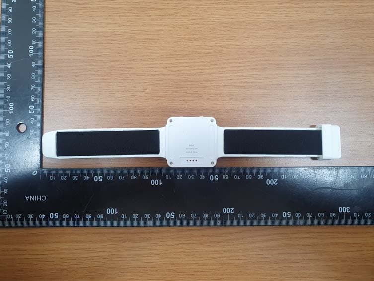
2ASP2KBD-002
May 05, 2021Bdot
Equipment Class
DTS - Digital Transmission System