2ASP4-HK30360 Dash Cam
Shenzhen Qihoo Intelligent Technology Co., Ltd.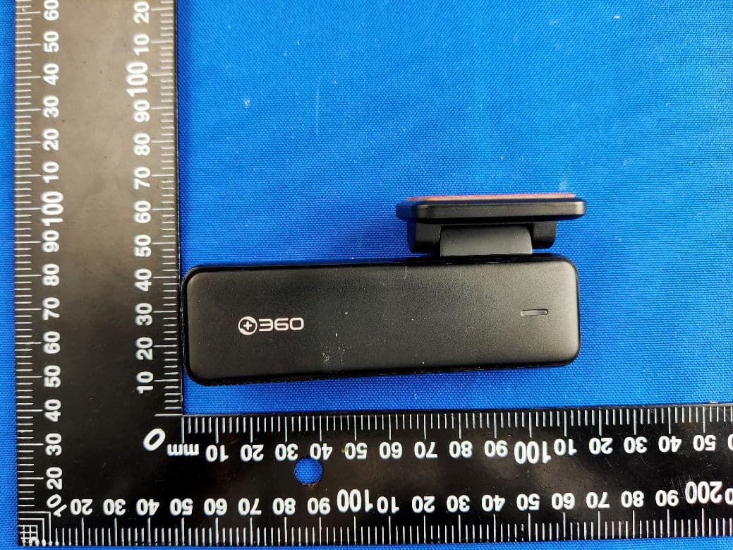
Click to zoom
Application Details
- Equipment Class
- DTS - Digital Transmission System
- Date of Grant
- Apr 28, 2021
- Application Purpose
- Original Equipment
- Date of Application
- Apr 28, 2021
- Equipment Note
- 360 Dash Cam
- Frequency Range
- 2412.00000000 - 2462.00000000
- Country
- China
Documents & Files
Document Text
Text extracted from the exhibit documents filed with the FCC. Open a document above to read the original.
Users Manual
Videos and pictures captured from the dash cam can be checked through the connected App. Search in the App store or scan the QR code below to download the 360 Dash Cam. Download the 360 Dash Cam App To ensure correct and safe use, please scan the QR code below and read the operation guide carefully before using. Operation Guide Apply the static sticker on the recommended area (dotted line) of the front windshield as shown in the figure below. Please clean the glass first and remove air bubbles in-between when installing. 1) Apply the static sticker Installation Please apply the sticker in the dotted line area. Install the cable from the upper front windshield, A-pillar, passenger console box to the cigar lighter as the figure shows, and then connect to the power of the cigar lighter. Notes: The cable can be hidden under the A-pillar sealing tape by using the cable crowbar. The cigar lighter position differs and the figure is only for reference. 3) Install cable and power. Please stick the sticker in the dotted line area. Tear off the 3M protective film, and attach the cam bracket to the static sticker. Tips: 1.Connect the bracket to the dash cam as shown in the figure below. 2.Adjust the cam to an appropriate angle. 2) Install the dash cam Product Overview Kabloyu şekilde gösterildiği gibi ön camın üst kısmından, A direğinden, yolcu konsol kutusundan çakmak soketine çekin ve daha sonra çakmak soketinin enerjisini bağlayın. Notlar: Kablo, kablo pensesi kullanılarak A direğinin contasının altına gizlenebilir. Çakmak soketinin yeri farklılık gösterebilir, şekil yalnızca referans amaçlıdır. 3.Kablo ve güç bağlantılarını yapın. Lütfen etiketi noktalarla gösterilen alana yapıştırın. 3M koruyucu filmi çıkarın ve kameranın braketini sabit etikete tutturun. İpuçları: 1.Braketi araç kamerasına aşağıdaki şekilde gösterildiği gibi bağlayın. 2.Kamerayı uygun bir açıya ayarlayın. 2) Araç kamerasının kurulumu Como se muestra en la figura, pase el cable de alimentación a lo largo de la parte superior del vidrio frontal, el pilar A y la caja de almacenamiento de la posición del copiloto hasta las proximidades del puerto del encendedor de cigarrillos y conecte la fuente de alimentación del encendedor de cigarrillos. Nota: Puede utilizar la palanca del cableado en la caja para enterrar el cable de alimentación debajo de la cinta de sellado del pilar A. La posición del puerto del encendedor de cigarrillos varia según los diferentes vehículos así que la imagen es solo para referencia 3) El cableado y la conexión de energía Pegue la película electrostática del vidrio en el marco punteado Quite la película protectora adhesiva 3M con la que pegue el soporte del sistema CarLog a la pegatina electrostática. Nota: 1. Conecte el soporte al sistema CarLog como se muestra en la siguiente figura. 2. Ajuste el sistema CarLog a un ángulo apropiado. 2) Pegar el sistema CarLog Разместите кабель питания сверху вдоль передней стеклянной поверхности, опоры A и контейнера блока дополнительного управления, в зоне с гнездом прикуривателя и подключите к нему кабель питания, как показано на изображении. Совет: кабель питания можно уплотнить вокруг опоры А герметизирующей лентой, используя ключ для прокладки соединений, идущий в комплекте. Положение гнезда прикуритвателя может отличаться в зависимости от модели. Изображение предоставлено только для справки. 3) Размещение провода и подключение к источнику питания Наклейте электростатическую пленку на стекло в зоне, указанной пунктирной линией Отсоедините клейкую защитную пленку 3M и поместите крепление регистратора на электростатический стикер. Советы: 1. Подключите крепление регистратора в соответствии с изображением ниже. 2. Отрегулируйте угол регистратора по необходимости. 2) Установка регистратора Precautions For Use Of The Charger • When the product is charging, the power outlet should be installed near the product and should be easily accessible. • When the charging completes or the product is not charging, please disconnect the charger from this product and unplug the charger from the power outlet. • Do not drop or hit the charger. If the charger housing is damaged, please contact the after-sales service center for replacement. • If the charger plug or power line is damaged, do not continue to use it in case of electric shock or fire. • The charger is not waterproof. Avoid use in the kitchen, bathroom, or other high temperature or excessively humid areas. Misuse may lead to electric shock, fire, or other hazards, and may damage the charger. • Do not short circuit, dismantle or modify the charger, otherwise it will cause personal injury, electric shock, fire and other hazards or damage the charger. • Do not touch the power line, product or charger with wet hands in case of short circuit, breakdown or electric shock. Precautions For Use Of The Battery • Do not dismantle or modify the built-in battery by yourself, so as not to damage the battery, generate heat and cause fire. • Do not throw the battery into the fire or place it in a hot place, or it will cause a fire or explosion. • Do not use the battery for other purposes. • Do not use any damaged charger or battery. • If the battery is deformed, discolored, damaged, or leaking stop use immediately. Contact the after-sales service center to replace the battery, in order to avoid danger. Note: Some electronic components are marked "X" in the table, such as high voltage resistors, ceramic resistors, and diodes. Their quantity of Pb may exceed 0.1% due to high-performance consideration. As the core in the screws and in the data cable is made of high-quality alloy, Pb may also exceed 0.1%.All of these items comply with the exemption conditions of EU's RoHS directive, and no alternative technologies or components can be applied at present. Shenzhen Qihoo Intelligent Technology Co., Ltd. Room 201, Block A, No. 1, Qianwan Road 1,Qianhai Shenzhen-Hong Kong Cooperation Zone Shenzhen, China. ” EU Declaration of Conformity Product descr…
Text truncated - open the document above for the full version.
External Photos
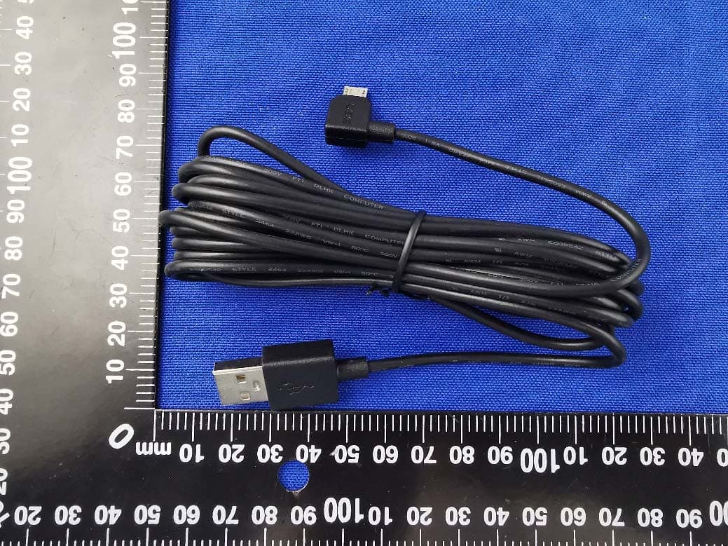
Annex No.: BL-SZ2110919-AW 1 / 6 EUT EXTERNAL PHOTOS FRONT VIEW OF EUT REAR VIEW OF EUT Annex No.: BL-SZ2110919-AW 2 / 6 CLOSE-UP LEFT SIDE VIEW OF EUT Annex No.: BL-SZ2110919-AW 3 / 6 RIGHT SIDE OF EUT TOP VIEW OF EUT Annex No.: BL-SZ2110919-AW 4 / 6 BOTTOM VIEW OF EUT Accessory-Car Charger Annex No.: BL-SZ2110919-AW 5 / 6 CLOSE-UP Accessory-USB Cable Annex No.: BL-SZ2110919-AW 6 / 6 Accessory-TF Card
Internal Photos
Annex No.: BL-SZ2110919-AI 1 / 4 EUT INTERNAL PHOTOS EUT UNCOVER VIEW EUT UNCOVER VIEW Annex No.: BL-SZ2110919-AI 2 / 4 EUT UNCOVER VIEW MAIN BOARD TOP VIEW Annex No.: BL-SZ2110919-AI 3 / 4 MAIN BOARD REAR VIEW (WITH SHIELDING) b MAIN BOARD REAR VIEW (WITHOUT SHIELDING) RF Chip Steel Antenna Annex No.: BL-SZ2110919-AI 4 / 4 Battery Photo (FRONT) Battery Photo (REAR)
RF Exposure Info
RF Exposure Evaluation for FCC ID: 2ASP4-HK30 Refer user manual this device is a 360 Dash Cam, and this device was designed used in Mobile devices that the minimum distance between human’s body is 20cm. Based on the 47CFR 2.1091, this device belongs to Mobile device. The definition of the category as following: Mobile Derives: CFR Title 47 §2.1091(b) (b) For purposes of this section, a mobile device is defined as a transmitting device designed to be used in other than fixed locations and to generally be used in such a way that a separation distance of at least 20 centimeters is normally maintained between the transmitter’s radiating structure(s) and the body of the user or nearby persons. FCC KDB 447498 D01 General RF Exposure Guidance v06 Limit Devices operating in standalone mobile exposure conditions may contain a single transmitter or multiple transmitters that do not transmit simultaneously. A minimum test separation distance ≥ 20 cm is required between the antenna and radiating structures of the device and nearby persons to apply mobile device exposure limits. The distance must be fully supported by the operating and installation configurations of the transmitter and its antenna(s), according to the source-based time-averaged maximum power requirements of § 2.1091(d)(2). In cases where cable losses or other attenuations are applied to determine compliance, the most conservative operating configurations and exposure conditions must be evaluated. The minimum test separation distance required for a device to comply with mobile exposure conditions must be clearly identified in the installation and operating instructions, for all installation and exposure conditions, to enable users and installers to comply with RF exposure requirements. For mobile devices that have the potential to operate in portable device exposure conditions, similar to the configurations described in § 2.1091(d)(4), a KDB inquiry is required to determine the SAR test requirements for demonstrating compliance. When the categorical exclusion provision of § 2.1091(c) applies, the minimum test separation distance may be estimated, when applicable, by simple calculations according to plane-wave equivalent conditions, to ensure the transmitter and its antenna(s) can operate in manners that meet or exceed the estimated distance. The source-based time-averaged maximum radiated power, according to the maximum antenna gain, must be applied to calculate the field strength and power density required to establish the minimum test separation distance. When the estimated test separation distance becomes overly conservative and does not support compliance, MPE measurement or computational modeling may be used to determine the required minimum separation distance. According to FCC Part 1.1307, systems operating under the provisions of this section shall be operated in a manner the ensures that the public is not exposed to radio frequency energy level in excess of the commission’s guidelines. Limits for General Population/ Uncontrolled Exposure Frequency Range (MHz) Electric Field Strength(E)(V/m) Magnetic Field Strength (H)(A/m) Power Density (S)(mW/cm 2 ) 0.3-1.34 614 1.63 (100)* 1.34-30 824/f 2.19/f (180/f2)* 30-300 27.5 0.073 0.2 300-1500 f/1500 1500-100,000 1.0 MPE calculation formula Where: S = power density P = output power (mW) G = power gain of the antenna in the direction of interest relative to an isotropic radiator R = Separation distance between radiator and human body (cm) Test data WIFI Mode 802.11b 802.11g 802.11n20 Low Middle High Low Middle High Low Middle High Peak Power (dBm) 16.43 15.95 15.11 15.61 15.40 14.07 15.75 15.30 14.35 Note: This report listed the worst case EIRP/ERP value, please refer to RF test report for more details. Turn-up power Mode Range (dBm) 2.4G WIFI 802.11b 15.00-17.00 802.11g 14.00-16.00 802.11n20 14.00-16.00 Test result Evolution mode Maximum peak output power (dBm) Antenna Gain (typical) (dBi): Total Power(mw) Distance (cm) Limit of Power Density (mW/cm²) Power Density (mW/cm²) Verdict WIFI 17.00 2.0 79.43 20 1.00 0.0158 Pass Note: 1. The 360 Dash Cam work frequency range used is 2400 MHz ~ 2483.5 MHz, the result close to the limit by the above formula. 2. More power list please refer to RF test report. Conclusion: RF exposure Evaluation Results: Compliance
Test Report
Report No.: BL-SZ2110919-601 2 / 66 Revision History Version Issue Date Revisions Content Rev. 01 Apr. 25, 2021 Initial Issue TABLE OF CONTENTS 1 ADMINISTRATIVE DATA (GENERAL INFORMATION) ........................................................................ 5 1.1 Identification of the Testing Laboratory ..................................................................................... 5 1.2 Identification of the Responsible Testing Location .................................................................... 5 1.3 Laboratory Condition ................................................................................................................ 5 1.4 Announce ................................................................................................................................. 5 2 PRODUCT INFORMATION ................................................................................................................... 6 2.1 Applicant Information ................................................................................................................ 6 2.2 Manufacturer Information .......................................................................................................... 6 2.3 Factory Information ................................................................................................................... 6 2.4 General Description for Equipment under Test (EUT) ............................................................... 6 2.5 Technical Information ............................................................................................................... 7 2.6 Additional Instructions .............................................................................................................. 9 3 SUMMARY OF TEST RESULTS ......................................................................................................... 10 3.1 Test Standards ....................................................................................................................... 10 3.2 Verdict .................................................................................................................................... 10 4 GENERAL TEST CONFIGURATIONS ................................................................................................ 11 4.1 Test Environments .................................................................................................................. 11 4.2 Test Equipment List ................................................................................................................ 11 4.3 Measurement Uncertainty ....................................................................................................... 12 4.4 Description of Test Setup ....................................................................................................... 13 4.4.1 For Antenna Port Test ............................................................................................................ 13 4.4.2 For AC Power Supply Port Test .............................................................................................. 13 4.4.3 For Radiated Test (Below 30 MHz) ......................................................................................... 14 4.4.4 For Radiated Test (30 MHz-1 GHz) ........................................................................................ 14 4.4.5 For Radiated Test (Above 1 GHz) .......................................................................................... 15 4.5 Measurement Results Explanation Example ........................................................................... 16 Report No.: BL-SZ2110919-601 3 / 66 4.5.1 For conducted test items: ....................................................................................................... 16 4.5.2 For radiated band edges and spurious emission test: ............................................................. 16 5 TEST ITEMS ....................................................................................................................................... 17 5.1 Antenna Requirements ........................................................................................................... 17 5.1.1 Relevant Standards ................................................................................................................ 17 5.1.2 Antenna Anti-Replacement Construction ................................................................................ 17 5.1.3 Antenna Gain ......................................................................................................................... 17 5.2 Output Power ......................................................................................................................... 18 5.2.1 Test Limit ................................................................................................................................ 18 5.2.2 Test Setup .............................................................................................................................. 18 5.2.3 Test Procedure ....................................................................................................................... 18 5.2.4 Test Result ............................................................................................................................. 19 5.3 6dB Bandwidth ....................................................................................................................... 20 5.3.1 Limit........................................................................................................................................ 20 5.3.2 Test Setup .............................................................................................................................. 20 5.3.3 Test Procedure ....................................................................................................................... 20 5.3.4 Test Result ..…
Text truncated - open the document above for the full version.
Test Setup Photos
Annex No.: BL-SZ2110919-AR 1 / 3 TEST SETUP PHOTOS 1 Radiated Test Photo Below 30MHz 30MHz-1GHz Annex No.: BL-SZ2110919-AR 2 / 3 Close-up Above 1GHz Annex No.: BL-SZ2110919-AR 3 / 3 Close-up 2 Conducted Test Photo Conducted Test-WIFI
Contact Information
Applicant
Kevin Song(QA Manager)
Test Firm
Shenzhen BALUN Technology Co., Ltd.Hanson Lin
[email protected]86-755-66833830
Technical Specifications
| # | Rule Parts | Frequency Range | Power Output |
|---|---|---|---|
| 1 | 15C | 2.41 GHz - 2.46 GHz | 43.95 mW |
Other Applications from Shenzhen Qihoo Intelligent Technology Co., Ltd.
2ASP4-G500H
Sep 07, 2020360 Dash Cam
Equipment Class
DTS - Digital Transmission System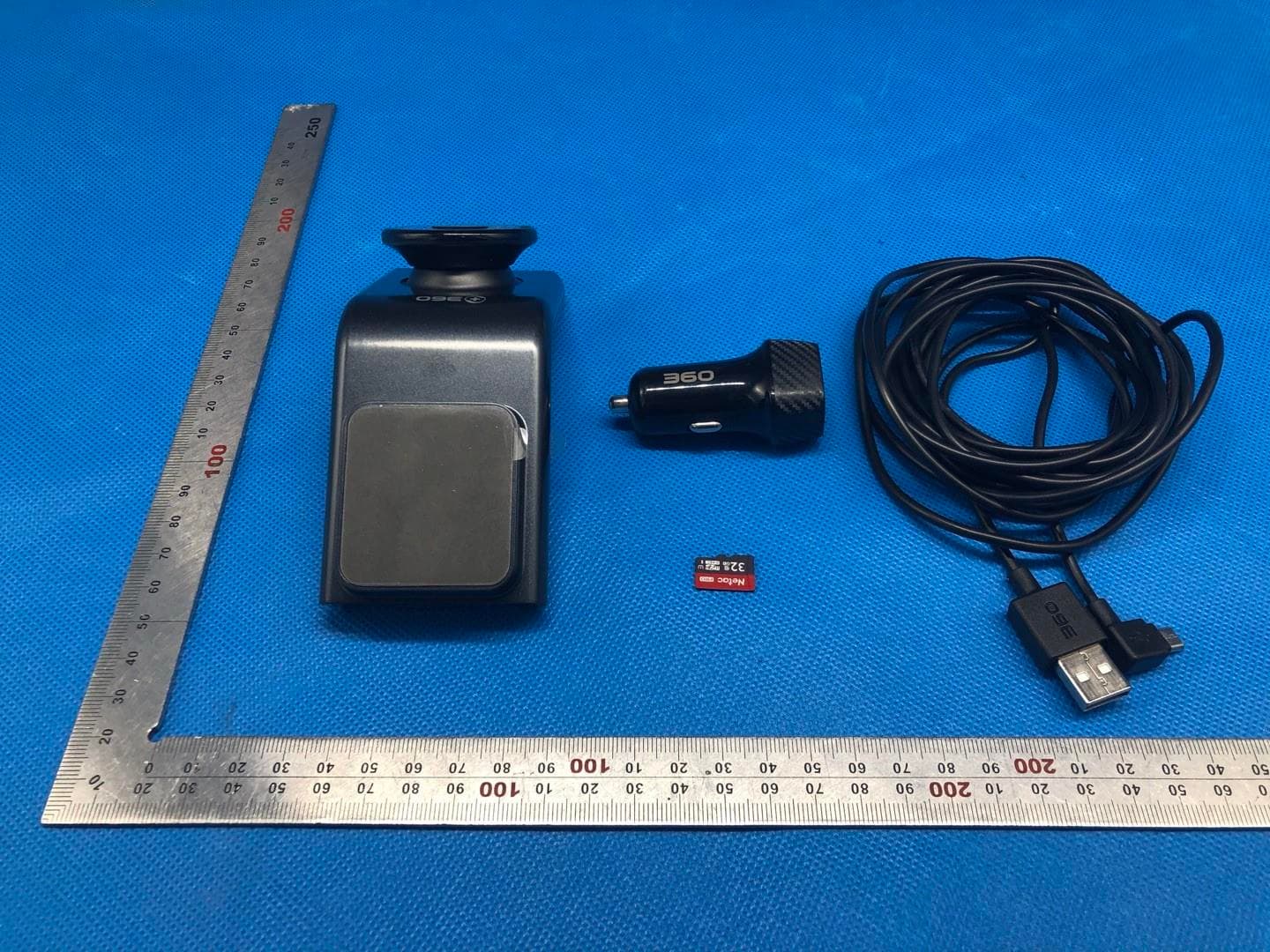
2ASP4J635
Aug 13, 2020360 Dash Cam
Equipment Class
DTS - Digital Transmission System