2ASQOP003110mmWave RADAR intended for non-automobile motorized devices
Patroness, LLC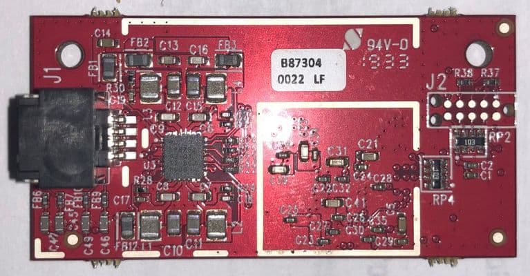
Click to zoom
Application Details
- Equipment Class
- VRD - Part 95 Vehicular Radar Systems
- Date of Grant
- Jan 15, 2020
- Application Purpose
- Original Equipment
- Date of Application
- Jan 15, 2020
- Equipment Note
- mmWave RADAR intended for non-automobile motorized devices
- Frequency Range
- 77000.00000000 - 81000.00000000
- Company
- Patroness, LLC
- Country
- United States
Documents & Files
Document Text
Text extracted from the exhibit documents filed with the FCC. Open a document above to read the original.
Users Manual
Radar Manual & Integrator Instructions These module integration instructions provide OEM integrator instructions for using the Patroness RADAR module. Please review and understand the conditions, limitations, and authorized uses of this module prior to integration. Overview of Module Figure 1. Patroness RADAR module. The Patroness RADAR module is a mmWave sensor based on FMCW) radar technology capable offrequency-modulated continuous wave ( operation in the 76- to 81-GHz bandwidth up to 4 GHz continuous chirp. It is built with a Texas Instruments IWR1443 System on Chip (SoC) main processor and integrated custom 3 Tx, 4 Rx antenna array capable of .generating x,y,z coordinates for up to 100 unique targets in its field of view Communication with the module is accomplished via . SPI protocol (Serial Peripheral Interface) The module is intended for integration into non-automobile motorized devices such as powered mobile chairs, mobility scooters, electronic conveyance vehicles, riding lawn mowers, grocery carts, all-terrain vehicles (ATVs), golf carts, and other mobile systems. It is not intended to be used in automobiles (passenger cars, trucks, passenger buses, and other passenger or property transporting motorized vehicles intended for licensed operation on state and national highways) or for fixed applications. Features Precise, non-contact target tracking measurement for multiple objects Low power and data processing requirements compared to competing approaches such as a scanning LIDAR Easy to use serial interface RoHS Compliant Performance Characteristics The following table describes typical performance characteristics of the default configuration of the Patroness RADAR module. The values given are based on controlled range testing without any enclosure or housing. Enclosure and mechanical configuration impacts the performance of the system and integrators should confirm performance for their unique application prior to release. ParameterValueNotes Frequency76-81 GHz coverage with 4-GHz bandwidth- Transmit PowerUp to 0.98 dBmEIRP Vertical FOV90 degrees- Horizontal FOV95 degrees- Power UsageLess than 2 WattsTypical, active Data Rate50 KBpsTypical, active Max Reports100Maximum number of simultaneous, individual reports from sensor Max Range6 metersMax distance an object can be detected Min Range6 cmClosest distance an object can be detected Resolution4 cmRange measurement resolution Applicable Rules FCC ID: 2ASQO-P003110 This device complies with part 95 and part 15 of the FCC Rules. Operation is subject to the following two conditions: (1) This device may not cause harmful interference, and (2) this device must accept any interference received, including interference that may cause undesired operation. Note: This equipment has been tested and found to comply with the limits for a Class B digital device, pursuant to part 15 of the FCC Rules. These limits are designed to provide reasonable protection against harmful interference in a residential installation. This equipment generates, uses and can radiate radio frequency energy and, if not installed and used in accordance with the instructions, may cause harmful interference to radio communications. However, there is no guarantee that interference will not occur in a particular installation. If this equipment does cause harmful interference to radio or television reception, which can be determined by turning the equipment off and on, the user is encouraged to try to correct the interference by one or more of the following measures: —Reorient or relocate the receiving antenna. —Increase the separation between the equipment and receiver. —Consult the dealer or an experienced radio/TV technician for help. IC: 24864-P003110 This device complies with Industry Canada RSS 251 and RSS-GEN standards. Operation is subject to the following two conditions: (1) this device may not cause interference, and (2) this device must accept any interference, including interference that may cause undesired operation of the device. Cet appareil est conforme avec Industrie Canada exempts de licence standard RSS 251 et RSS-GEN. Son fonctionnement est soumis aux deux conditions suivantes: (1) cet appareil ne doit pas provoquer d'interférences et (2) cet appareil doit accepter toute interférence, y compris celles pouvant causer un mauvais fonctionnement de l'appareil. Operating Conditions DescriptionHighLow Operating Temperature40 C-10 C Storage Temperature80 C-40 C Water & DustNot rated, dependent on enclosure Physical Mounting & Packaging Do Not Modify Changes or modifications not expressly approved by Patroness may void your authority to operate the equipment. ESD Protection This module can be damaged by . PatronessESD recommends that all modules be handled with appropriate precautions. Failure to observe proper handling and installation procedures can cause damage. ESD damage can range from subtle performance degradation to complete device failure. Antenna Care Particular care should be taken to avoid scratching or damaging the antenna array. The module is intended to be mounted in an enclosure for protection against the elements and damage. The board nominal thickness is 1.6 mm. Module Mounting Figure 2. Patroness RADAR module dimensions. Electrical & Communication Interface The interface connector on the RADAR accepts a Molex PN 5054320801 8-Position Rectangular Housing Connector. The pinout is detailed below. PinDefinitionDetails 1+5V5 Volts DC 2SPI_CSChip select 3SPI_MISOSerial Master In/Slave Out 4SPI_HOST_INTRSerial interrupt 5SPI_CLKSerial clock from master 6PMIC_ENSet high to enable power to main processor 7SPI_MOSISerial Master Out/Slave In 8GNDGround The module must be powered by an external 5 Volt power supply (0.5 Amp current limit). When 5 Volt power is applied to the module, and the he power up of the PMIC takes approximately 5 ms once thePMIC enable pin is set high, the IWR1443 SoC is powered for use. Note, that t 1. 2. enable signal is released…
Text truncated - open the document above for the full version.
Cover Letter(s)
1(1) Patroness, LLC March 15, 2019 Attention: Application Examiner RE: Request for Confidentiality Applicant: Patroness, LLC FCC ID: 2ASQO-P003110 To Whom It May Concern: Request is hereby submitted by Patroness, LLC to withhold permanently from public review certain portions of the application for equipment certification for the referenced FCC identifiers. This request for confidentiality is made pursuant to 47 CFR 0.457(d) and 0.459 of the FCC Rules. In particular, the following sections of the application are to be kept permanently confidential: • Detailed Block Diagrams • Detailed Operational/Functional Description • Schematics • Bill of Materials/Parts list Patroness, LLC has invested considerable time and materials in research and development to produce the referenced product. Disclosure of the permanently confidential portions of this application to competitors would not only give them significant competitive advantages in developing similar products, but would also disclose successful implementation of unpublished, leading edge technology developed by us. The fee for confidentiality has been submitted along with the fee for certification. If you have questions or need further information, please contact the undersigned. Sincerely, Jered Dean CTO Patroness, LLC
Cover Letter(s)
Patroness, LLC March 15, 2019 Federal Communications Commission 445 12 th Street SW Washington, DC 20554 Subject: Limited Agency Agreement Patroness, LLC FCC ID: 2ASQO-P003110 To Whom It May Concern: We, Patroness, LLC, hereby authorized Intertek Testing Services to act as our Agent for the purpose of preparing application for FCC ID number 2ASQO-P003110 under all applicable parts of the FCC rules and regulations. The effective date of this limited agency agreement is March 15, 2019. The Limited Agency Agreement expires on December 31, 2019, unless sooner terminated or extended by written notice to Intertek Testing Services and the Federal Communications Commission. This is to advise that we are in full compliance with the Anti-Drug Abuse Act. The applicant is not subject to a denial of federal benefits pursuant to Section 5301 of the Anti-Drug Act of 1988, 21 U.S.C. 862, and no party to the application is subject to a denial of federal benefits pursuant to that section. If you have any questions or comments, please do not hesitate to contact me. Sincerely, Jered Dean CTO
Cover Letter(s)
Patroness, LLC RE FCC ID: 2ASQO-P003110 To the certification reviewer: We are hereby applying for full modular approval of the above-referenced FCC ID, based on compliance with all of the criteria as detailed below. Sincerely, Jered Dean CTO Part 15 Unlicensed Single Modular Transmitter Approval Justification per 15.212 Requirement per 15.212 reference (i) The radio elements of the modular transmitter must have their own RF shielding. See external and internal photos. No radio elements exposed outside shielding. (ii) The modular transmitter must have buffered modulation/data inputs (if such inputs are provided. Not Applicable (iii) The modular transmitter must have its own power supply regulation. See schematic. Power supply regulation is provided by circuitry on the module. (iv) The modular transmitter must comply with the antenna and transmission system requirements of §§ 15.203, 15.204(b) and 15.204(c). See schematic. The antenna is permanently attached. (v) The modular transmitter must be tested in a stand-alone configuration, i.e., the module must not be inside another device during testing for compliance with Part 15 parameters. See test report. Testing was performed with the module outside of the host, as shown in the test setup photos. (vi) The modular transmitter must be equipped with either a permanently affixed label or must be capable of electronically displaying its FCC identification number. If the FCC ID is not visible when the module is installed inside another device, then the outside of the device into which the module is installed must also display a label referring to the enclosed module. See images. The module has a permanently affixed label displaying its FCC identification number. (vii) The modular transmitter must comply with any specific rules or operating requirements that ordinarily apply to a complete transmitter and the manufacturer must provide adequate instructions along with the module to explain any such requirements. A copy of these instructions must be included in the application for equipment authorization. The module complies fully with the operating requirements as demonstrated in the test report exhibit. (viii) The modular transmitter must comply with any applicable RF exposure requirements in its final configuration. The module complies fully with the operating requirements as demonstrated in the test report exhibit.
External Photos
P003110 External Photos The following documentation is provided to support the processing of the FCC and ISED modular certifications for the Patroness RADAR module. TitleCodeNotes FCC Reg. Number0028320943Patroness, LLC IC Company Number24864Patroness, LLC FCC Grantee Code2ASQOFCC Code 1 from Form 159 FCC Identifier/UPNP003110Patroness Part Number External Photos Figure 1. Patroness RADAR Module Front Figure 2. Patroness RADAR Module Back Figure 3. Patroness RADAR Module Side
ID Label/Location Info
P003110 ID Label and Location The following documentation is provided to support the processing of the FCC and ISED modular certifications for the Patroness RADAR module. TitleCodeNotes FCC Reg. Number0028320943Patroness, LLC IC Company Number24864Patroness, LLC FCC Grantee Code2ASQOFCC Code 1 from Form 159 FCC Identifier/UPNP003110Patroness Part Number ID Label Label artwork: Patroness, LLC P003110 FCC ID: 2ASQO-P003110 IC: 24864-P003110 Figure 1. Module with Label on Product
Internal Photos
P003110 Internal Photos The following documentation is provided to support the processing of the FCC and ISED modular certifications for the Patroness RADAR module. TitleCodeNotes FCC Reg. Number0028320943Patroness, LLC IC Company Number24864Patroness, LLC FCC Grantee Code2ASQOFCC Code 1 from Form 159 FCC Identifier/UPNP003110Patroness Part Number Internal Photos The following photographs show construction, component placement, chassis assembly, and antennas. Figure 1. Key Module Component Placement (Front w/shield removed) Figure 2. Key Module Component Placement (Back)
Test Report
Patroness, LLC TEST REPORT SCOPE OF WORK EMISSIONS TESTING – MODEL P003110 REPORT NUMBER 103842901BOX‐013 ISSUE DATE REVISED DATE 04‐September‐2019 24‐January‐2020 PAGES 65 DOCUMENT CONTROL NUMBER Non‐Specific Radio Report Shell Rev. December 2017 © 2017 INTERTEK Non-Specific Radio Report Shell Rev. December 2017Page 2 of 65 Patroness, LLC, Model: P003110 EMISSIONS TEST REPORT (FULL COMPLIANCE) Report Number: 103842901BOX-013 Project Number: G103842901 Report Issue Date: 09/04/2019 Revised Date: 10/16/2019 Revision Date: 01/15/2020 Revision Date: 01/24/2020 Model(s) Tested:P003110 Model(s) Partially Tested:None Model(s) Not Tested but declared equivalent by the client:None Standards: FCC 47CFR Part 95, Subpart M:09/2019 RSS-251 Issue 2: 07/2018 RSS Gen Issue 5 March 2019 Amendment 1 RSS-102 Issue 5 March 2015 Tested by: Client: Intertek Testing Services NA, Inc. 70 Codman Hill Road Boxborough, MA 01719 USA Patroness, LLC 101 Creekside Crossing Suite 1700 #244 Brentwood, TX 37027 USA Report prepared by Report reviewed by Vathana Ven/EMC Staff Engineer Kouma Sinn /EMC Staff Engineer This report is for the exclusive use of Intertek's Client and is provided pursuant to the agreement between Intertek and its Client. Intertek's responsibility and liability are limited to the terms and conditions of the agreement. Intertek assumes no liability to any party, other than to the Client in accordance with the agreement, for any loss, expense or damage occasioned by the use of this report. Only the Client is authorized to permit copying or distribution of this report and then only in its entirety. Any use of the Intertek name or one of its marks for the sale or advertisement of the tested material, product or service must first be approved in writing by Intertek. The observations and test results in this report are relevant only to the sample tested. This report by itself does not imply that the material, product, or service is or has ever been under an Intertek certification program. Intertek Report Number: 103842901BOX-013 Issued: 09/04/2019 Revised date: 01 /24/2020 Non-Specific Radio Report Shell Rev. December 2017 Page 3 of 65 Patroness, LLC, Model: P003110 Table of Contents 1 Introduction and Conclusion .............................................................................................................. 4 2 Test Summary ...................................................................................................................................... 4 3 Client Information ................................................................................................................................ 5 4 Description of Equipment Under Test and Variant Models ............................................................. 5 5 System Setup and Method .................................................................................................................. 6 6 Maximum Power and Human RF exposure ....................................................................................... 8 7 Occupied Bandwidth ......................................................................................................................... 19 8 Unwanted Emissions ......................................................................................................................... 24 9 Frequency Stability ............................................................................................................................ 48 10 Appendix A – Mixer/Horn Calibration Certificates ...................................................................... 59 11 Revision History ............................................................................................................................. 65 Intertek Report Number: 103842901BOX-013 Issued: 09/04/2019 Revised date: 01 /24/2020 Non-Specific Radio Report Shell Rev. December 2017 Page 4 of 65 Patroness, LLC, Model: P003110 1 Introduction and Conclusion The tests indicated in section 2.0 were performed on the product constructed as described in section 4.0. The remaining test sections are the verbatim text from the actual data sheets used during the investigation. These test sections include the test name, the specified test Method, a list of the actual Test Equipment Used, documentation Photos, Results and raw Data. No additions, deviations, or exclusions have been made from the standard(s) unless specifically noted. Based on the results of our investigation, we have concluded the product tested complies with the requirements of the standard(s) indicated. The results obtained in this test report pertain only to the item(s) tested. Intertek does not make any claims of compliance for samples or variants which were not tested. 2 Test Summary Section Test full name Result 3 Client Information -- 4 Description of Equipment Under Test and Variant Models -- 5 System Setup and Method --- 6 Maximum Power and Human RF exposure FCC 47CFR Part 95, Subpart M:09/2019 RSS-251 Issue 2: 07/2018, ANSI C63.10:2013, RSS-102 Issue 5 March 2015 Pass 7 Occupied Bandwidth FCC 47CFR Part 95, Subpart M:09/2019 RSS-251 Issue 2: 07/2018, RSS Gen Issue 5 March 2019 Amendment 1, ANSI C63.10:2013 Pass 8 Unwanted Emissions FCC 47CFR Part 95, Subpart M:09/2019 RSS-251 Issue 2: 07/2018, RSS Gen Issue 5 March 2019 Amendment 1 , ANSI C63.10:2013 Pass 9 Frequency Stability FCC 47CFR Part 95, Subpart M:09/2019 RSS-251 Issue 2: 07/2018, RSS Gen Issue 5 March 2019 Amendment 1, ANSI C63.10:2013 Pass 10 Appendix A – Mixer/Horn Calibration Certificates -- 11 Revision History -- Intertek Report Number: 103842901BOX-013 Issued: 09/04/2019 Revised date: 01 /24/2020 Non-Specific Radio Report Shell Rev. December 2017 Page 5 of 65 Patroness, LLC, Model: P003110 3 Client Information This EUT was tested at the request of: Client: Patroness, LLC 101 Creekside Crossing Suite 1700 #244 Brentwood, TX 37027 USA Contact: Jered Dean Telephone: 781-535-4736 Email: [email protected] 4 Description …
Text truncated - open the document above for the full version.
Test Setup Photos
Intertek Report Number: 103842901BOX-013 Issued: 09/04/2019 Non-Specific Radio Report Shell Rev. December 2017 Page 1 of 7 Patroness, LLC, Model: P003110 1.1 Setup Photograph: 9kHz-30MHz Intertek Report Number: 103842901BOX-013 Issued: 09/04/2019 Non-Specific Radio Report Shell Rev. December 2017 Page 2 of 7 Patroness, LLC, Model: P003110 30-1000MHz Intertek Report Number: 103842901BOX-013 Issued: 09/04/2019 Non-Specific Radio Report Shell Rev. December 2017 Page 3 of 7 Patroness, LLC, Model: P003110 1-18 GHz Intertek Report Number: 103842901BOX-013 Issued: 09/04/2019 Non-Specific Radio Report Shell Rev. December 2017 Page 4 of 7 Patroness, LLC, Model: P003110 18-40GHz Intertek Report Number: 103842901BOX-013 Issued: 09/04/2019 Non-Specific Radio Report Shell Rev. December 2017 Page 5 of 7 Patroness, LLC, Model: P003110 40-60GHz 60-90GHz Intertek Report Number: 103842901BOX-013 Issued: 09/04/2019 Non-Specific Radio Report Shell Rev. December 2017 Page 6 of 7 Patroness, LLC, Model: P003110 90-140GHz 140-220GHz Intertek Report Number: 103842901BOX-013 Issued: 09/04/2019 Non-Specific Radio Report Shell Rev. December 2017 Page 7 of 7 Patroness, LLC, Model: P003110 220-231GHz
Contact Information
Applicant
Jered H Dean(CTO)
Technical Contact
Patroness, LLCJered H Dean
[email protected]6154864554
101 Creekside Crossing · Brentwood · United States
Non-Technical Contact
Patroness, LLCPeter Knapp
[email protected](615) 486-4554
Test Firm
Intertek Testing Services NA Inc.Yaqing Liu
[email protected]978 635 8662
Technical Specifications
| # | Rule Parts | Frequency Range | Power Output | Emission |
|---|---|---|---|---|
| 1 | 95M | 77.00 GHz - 81.00 GHz | 37.07 mW | 3G89F3X |