2ASR8MKNFC001Read-write card module
Qingdao Haier Biomedical Co Ltd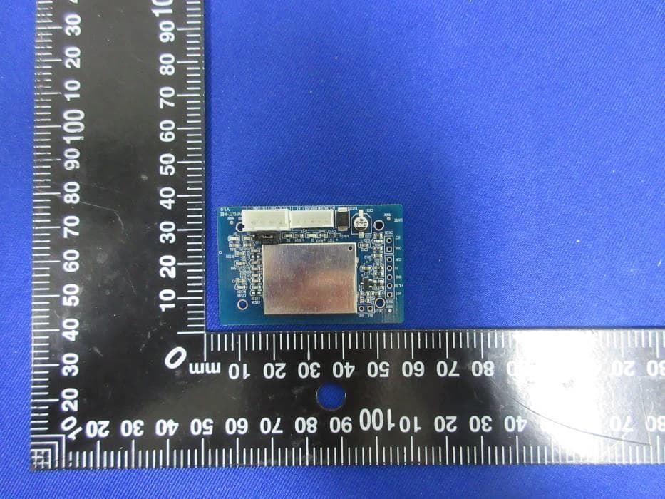
Click to zoom
Application Details
- Equipment Class
- DXX - Part 15 Low Power Communication Device Transmitter
- Date of Grant
- Nov 08, 2020
- Application Purpose
- Original Equipment
- Date of Application
- Oct 19, 2020
- Equipment Note
- Read-write card module
- Frequency Range
- 13.56000000 - 13.56000000
- Country
- China
Documents & Files
Document Text
Text extracted from the exhibit documents filed with the FCC. Open a document above to read the original.
Users Manual
1. Introduction MK-NFC-001 module is complied with 13.56MHz ISM band. 2. FEATURES Band 13.56MHz Dimensions 53mm*33mm*2.5mm power consumption Average current:<30mA Peak current:<100mA Reading distance TypeA:≧5cm Port I2C、UART transfer rate I2C: <100K UART: 19200bit/s Type Contact:SAM卡 Non-Contact:Mifare 1 S50、Mifare 1 S70、Mifare UltraLight、Mifare Desfire、PLUS CPU 卡、符合ISO14443A的逻辑加密卡和CPU卡、符合ISO14443B的卡片 Environment Operating temperature:-20〜80°C Humidity: 5%〜95°% Canada Statement This device contains licence-exempt transmitter(s)/receiver(s) that comply with Innovation, Science and Economic Development Canada’s licence-exempt RSS(s). Operation is subject to the following two conditions: 1. This device may not cause interference. 2. This device must accept any interference, including interference that may cause undesired operation of the device. L’émetteur/récepteur exempt de licence contenu dans le présent appareil est conforme aux CNR d’Innovation, Sciences et Développement économique Canada applicables aux appareils radio exempts de licence. L’exploitation est autorisée aux deux conditions suivantes : 1. L’appareil ne doit pas produire de brouillage; 2. L’appareil doit accepter tout brouillage radioélectrique subi, même si le brouillage est susceptible d’en compromettre le fonctionnement. Please notice that if the ISED certification number is not visible when the module is installed inside another device, then the outside of the device into which the module is installed must also display a label referring to the enclosed module. This exterior label can use wording such as the following: “Contains IC: 25370- MKNFC001” any similar wording that expresses the same meaning may be used. This equipment complies with IC RF radiation exposure limits set forth for an uncontrolled environment. This transmitter must not be co-located or operating in conjunction with any other antenna or transmitter. This equipment should be installed and operated with minimum distance 7.9 inches (20 cm) between the radiator & your body. Le présent appareil est conforme de ce matériel aux conformités ou aux limites d’intensité de champ RF, les utilisateurs peuvent sur l’exposition aux radiofréquences et la conformité and compliance d’acquérir les informations correspondante. l'appareil hôte doit porter une étiquette donnant le numéro de certification du module d'Industrie Canada, précédé des mots « Contient un module d'émission », du mot « IC: 25370-MKNFC001» ou d'une formulation similaire exprimant le même sens, comme suit This radio transmitter 25370-MKNFC001 has been approved by Innovation, Science and Economic Development Canada to operate with the antenna types listed below, with the maximum permissible gain indicated. Antenna types not included in this list that have a gain greater than the maximum gain indicated for any type listed are strictly prohibited for use with this device. Le présent émetteur radio 25370-MKNFC001 a été approuvé par Innovation, Sciences et Développement économique Canada pour fonctionner avec les types d'antenne énumérés ci-dessous et ayant un gain admissible maximal. Les types d'antenne non inclus dans cette liste, et dont le gain est supérieur au gain maximal indiqué pour tout type figurant sur la liste, sont strictement interdits pour l'exploitation de l'émetteur. The concrete contents to check are the following three points. 1) Must use following antenna. 2) Should be installed so that the end user cannot modify the antenna; 3) Feed line should be designed in 50ohm Fine tuning of return loss etc. can be performed using a matching network. Le contenu concret à vérifier sont les trois points suivants. 1) i l doit utiliser suivant de l'antenne. 2) doivent être installés de façon que l'utilisateur final ne peut pas modifier l'antenne 3) La ligne d’alimentation doit être conçue en 50ohm Le réglage précis de la perte de rendement, etc. peut être effectué en utilisant un réseau correspondant. Ant. Frequency (MHz) Model number Antenna Type Antenna Gain (dBi) 1 13.56 MK-NFC-001 PCB Antenna 0 FCC Statement This device complies with Part 15 of the FCC Rules. Operation is subject to the following two conditions: (1) this device may not cause harmful interference, and (2) this device must accept any interference received, including interference that may cause undesired operation. Caution: The user is cautioned that changes or modifications not expressly approved by the party responsible for compliance could void the user's authority to operate the equipment. Note: This equipment has been tested and found to comply with the limits for a Class B digital device, pursuant to part 15 of the FCC Rules. These limits are designed to provide reasonable protection against harmful interference in a residential installation. This equipment generates uses and can radiate radio frequency energy and, if not installed and used in accordance with the instructions, may cause harmful interference to radio communications. However, there is no guarantee that interference will not occur in a particular installation. If this equipment does cause harmful interference to radio or television reception, which can be determined by turning the equipment off and on, the user is encouraged to try to correct the interference by one or more of the following measures: —Reorient or relocate the receiving antenna. —Increase the separation between the equipment and receiver. —Connect the equipment into an outlet on a circuit different from that to which the receiver is connected. —Consult the dealer or an experienced radio/TV technician for help. FCC RF Radiation Exposure Statement: This equipment complies with FCC radiation exposure limits set forth for an uncontrolled environment. This equipment should be installed and operated with a minimum distance of 20cm between the radiator and any part of your body. The device must be professionally installed The intended use is generally not for the general public.It is generally for indu…
Text truncated - open the document above for the full version.
Cover Letter(s)
The module transmitter will be a single module Modular Approval Request FCC (Per 15.212) FCC ID: 2ASR8MKNFC001 Items to be covered Answer From Applicant 1. The radio elements of the modular transmitter must have their own shielding. The physical crystal and tuning capacitors may be located external to the shielded radio elements. Yes 2. The modular transmitter must have buffered modulation/data inputs (if such inputs are provided) to ensure that the module will comply with part 15 requirements under conditions of excessive data rates or over- modulation. Yes 3. The modular transmitter must have its own power supply regulation. Yes 4. The modular transmitter must comply with the antenna and transmission system requirements of §§15.203, 15.204(b) and 15.204(c). The antenna must either be permanently attached or employ a “unique” antenna coupler (at all connections between the module and the antenna, including the cable). The “professional installation” provision of §15.203 is not applicable to modules but can apply to limited modular approvals under paragraph (b) of this section. Yes 5. The modular transmitter must be tested in a stand-alone configuration, i.e., the module must not be inside another device during testing for compliance with part 15 requirements. Unless the transmitter module will be battery powered, it must comply with the AC line conducted requirements found in §15.207. AC or DC power lines and data input/output lines connected to the module must not contain ferrites, unless they will be marketed with the module (see §15.27(a)). The length of these lines shall be the length typical of actual use or, if that length is unknown, at least 10 centimeters to insure that there is no coupling between the case of the module and supporting equipment. Any accessories, peripherals, or support equipment connected to the module during testing shall be unmodified and commercially available (see §15.31(i)). Yes 6. The modular transmitter must be equipped with either a permanently affixed label or must be capable of electronically displaying its FCC identification number. (A) If using a permanently affixed label, the modular transmitter must be labeled with its own FCC identification number, and, if the FCC identification number is not visible when the module is installed inside another device, then the outside of the device into which the module is installed must also display a label referring to the enclosed module. This exterior label can use wording such as the following: “Contains Yes Transmitter Module FCC ID: XYZMODEL1” or “Contains FCC ID: XYZMODEL1.” Any similar wording that expresses the same meaning may be used. The Grantee may either provide such a label, an example of which must be included in the application for equipment authorization, or, must provide adequate instructions along with the module which explain this requirement. In the latter case, a copy of these instructions must be included in the application for equipment authorization. (B) If the modular transmitter uses an electronic display of the FCC identification number, the information must be readily accessible and visible on the modular transmitter or on the device in which it is installed. If the module is installed inside another device, then the outside of the device into which the module is installed must display a label referring to the enclosed module. This exterior label can use wording such as the following: “Contains FCC certified transmitter module(s).” Any similar wording that expresses the same meaning may be used. The user manual must include instructions on how to access the electronic display. A copy of these instructions must be included in the application for equipment authorization. 7. The modular transmitter must comply with any specific rules or operating requirements that ordinarily apply to a complete transmitter and the manufacturer must provide adequate instructions along with the module to explain any such requirements. A copy of these instructions must be included in the application for equipment authorization. Yes 8. Radio frequency devices operating under the provisions of this part are subject to the radio frequency radiation exposure requirements specified in §§1.1307(b), 1.1310, 2.1091, and 2.1093 of this chapter, as appropriate. Applications for equipment authorization of modular transmitters under this section must contain a statement confirming compliance with these requirements. The modular transmitter must comply with any applicable RF exposure requirements in its final configuration. Technical information showing the basis for this statement must be submitted to the Commission upon request. Yes Note: If compliance with one or more of the numbered requirements, listed above, cannot be demonstrated, it may be possible to obtain a “Limited Modular Approval” (LMA).
External Photos
UL-CCIC COMPANY LIMITED This report shall not be reproduced except in full, without the written approval of UL-CCIC COMPANY LIMITED. . Appendix I External Photographs UL-CCIC COMPANY LIMITED This report shall not be reproduced except in full, without the written approval of UL-CCIC COMPANY LIMITED. . Top View of EUT Bottom View of EUT
Internal Photos
UL-CCIC COMPANY LIMITED This report shall not be reproduced except in full, without the written approval of UL-CCIC COMPANY LIMITED. . Appendix II Internal Photographs UL-CCIC COMPANY LIMITED This report shall not be reproduced except in full, without the written approval of UL-CCIC COMPANY LIMITED. . Internal View of EUT-1 Antenna Location
Parts List/Tune Up Info
PMN: Read-write card module IC:25370-MKNFC001 Model: MK-NFC-001 FCC ID: 2ASR8MKNFC001 Label location
Test Report
10-EM-F0876 – Issue 1.0 The results reported herein have been performed in accordance with the laboratory’s terms of accreditation. This report shall not be reproduced except in full without the written approval of the Laboratory. The results in this report apply to the test sample(s) mentioned above at the time of the testing period only and are not to be used to indicate applicability to other similar products. This report does not imply that the product(s) has met the criteria for certification. FCC 47 CFR PART 15 SUBPART C ISED RSS-210 ISSUE 10 CERTIFICATION TEST REPORT For Read-write card module MODEL NUMBER: MK-NFC-001 PROJECT NUMBER: 4789002290 REPORT NUMBER: 4789002290-1 FCC ID: 2ASR8MKNFC001 IC: 25370-MKNFC001 ISSUE DATE: Sep. 17, 2020 Prepared for Qingdao Haier Biomedical Co.,Ltd Prepared by UL-CCIC COMPANY LIMITED No. 2, Chengwan Road, Suzhou Industrial Park, People’s Republic of China Tel: +86 769 22038881 Fax: +86 769 33244054 Website: www.ul.com REPORT NO.: 4789002290-1 Page 2 of 35 UL-CCIC COMPANY LIMITED This report shall not be reproduced except in full, without the written approval of UL-CCIC COMPANY LIMITED. Revision History Rev. Issue Date Revisions Revised By V0 09/17/2020 Initial Issue REPORT NO.: 4789002290-1 Page 3 of 35 UL-CCIC COMPANY LIMITED This report shall not be reproduced except in full, without the written approval of UL-CCIC COMPANY LIMITED. Summary of Test Results Clause Test Items FCC Rules Test Results 1 Transmitter AC Conducted Emissions Part 15.207 RSS-GEN Clause 8.8 PASS 2 Transmitter Fundamental Field Strength Part 15.225(a)(b)(c)(d) RSS-210 Clause B.6 RSS-GEN Clause 8.9 RSS-GEN Clause 8.10 PASS 3 Transmitter Radiated Emissions Part 15.209(a)/ 15.225(d) RSS-210 Clause B.6 RSS-GEN Clause 8.9 RSS-GEN Clause 8.10 PASS 4 Transmitter 99% Emission Bandwidth / 20dB Bandwidth Part 15.215 (c) RSS-GEN Clause 6.7 PASS 5 Transmitter Frequency Stability (Temperature & Voltage Variation) Part 15.225(e) RSS-210 Clause B.6 RSS-GEN Clause 8.11 PASS 6 Antenna Requirement FCC 15.203 PASS Remark: 1) The measurement result for the sample received is <Pass> according to < ANSI C63.10-2013, RSS-GEN , RSS-210, FCC CFR 47 Part 2, FCC CFR 47 Part 15> when <Accuracy Method> decision rule is applied. REPORT NO.: 4789002290-1 Page 4 of 35 UL-CCIC COMPANY LIMITED This report shall not be reproduced except in full, without the written approval of UL-CCIC COMPANY LIMITED. TABLE OF CONTENTS 1. ATTESTATION OF TEST RESULTS ................................................................................. 5 2. TEST METHODOLOGY ..................................................................................................... 6 3. FACILITIES AND ACCREDITATION ................................................................................. 6 4. CALIBRATION AND UNCERTAINTY ................................................................................ 7 4.1. MEASURING INSTRUMENT CALIBRATION .............................................................. 7 4.2. MEASUREMENT UNCERTAINTY ............................................................................... 7 5. EQUIPMENT UNDER TEST ............................................................................................... 8 5.1. DESCRIPTION OF EUT .............................................................................................. 8 5.2. MAXIMUM OUTPUT POWER...................................................................................... 9 5.3. CHANNEL LIST ........................................................................................................... 9 5.4. DESCRIPTION OF AVAILABLE ANTENNAS .............................................................. 9 5.5. TEST ENVIRONMENT ................................................................................................ 9 5.6. DESCRIPTION OF TEST SETUP ...............................................................................10 5.7. MEASURING INSTRUMENT AND SOFTWARE USED ..............................................11 6. ANTENNA PORT TEST RESULTS ...................................................................................12 6.1. AC Conducted Spurious Emissions ............................................................................12 6.2. RADIATED EMISSION ...............................................................................................17 6.2.1. FUNDAMENTAL FIELD STRENGTH...................................................................24 6.2.2. SPURIOUS EMISSIONS BELOW 1G ..................................................................25 6.2.3. SPURIOUS EMISSIONS BELOW 30M ................................................................27 6.3. 99%/20dB BANDWIDTH .............................................................................................30 6.4. TRANSMITTER FREQUENCY STABILITY.................................................................32 7. ANTENNA REQUIREMENTS ............................................................................................35 REPORT NO.: 4789002290-1 Page 5 of 35 UL-CCIC COMPANY LIMITED This report shall not be reproduced except in full, without the written approval of UL-CCIC COMPANY LIMITED. 1. ATTESTATION OF TEST RESULTS Applicant Information Company Name: Qingdao Haier Biomedical Co.,Ltd Address: HAIER INDUSTRIAL PARK ECONOMIC TECHNOLOGY DEVELOPMENT ZONE ,QINGDAO,SHANDONG 266510 CHINA Manufacturer Information Company Name: Qingdao Haier Biomedical Co.,Ltd Address: HAIER INDUSTRIAL PARK ECONOMIC TECHNOLOGY DEVELOPMENT ZONE ,QINGDAO,SHANDONG 266510 CHINA EUT Description Product Name Read-write card module Model Name MK-NFC-001 Sample Number 2350244 Data of Receipt Sample Jul. 01, 2020 Date Tested Jul. 01, 2020~ Sep. 16, 2020 APPLICABLE STANDARDS STANDARD TEST RESULTS CFR 47 Part 15 Subpart C PASS RSS 210 ISSUE 10 PASS Prepared By: Reviewed By: Jason Yang Tom Tang Engineer Engineer Project Associate Authorized By: Chris Zhong Laboratory Leader REPORT NO.: 47890…
Text truncated - open the document above for the full version.
Test Setup Photos
Appendix I Setup Photographs RADIATED RF MEASUREMENT SETUP (30MHz ~ 1 GHz) RADIATED RF MEASUREMENT SETUP (Below 30MHz) CLOSE SETUP PHOTO OF EUT POWERLINE CONDUCTED EMISSIONS MEASUREMENT SETUP
Contact Information
Applicant
Yuqiang Sun
Technical Contact
UL-CCIC Company LimitedChris Zhong
[email protected]+86 512 68758596
No. 2, Chengwan Road, Suzhou Industrial Park, Suzh · Suzhou · China
Test Firm
UL-CCIC Company LimitedChris Zhong
[email protected]+86 512 68758596
Technical Specifications
| # | Rule Parts | Frequency Range | Power Output |
|---|---|---|---|
| 1 | 15C | 13.56 MHz - 13.56 MHz | - |