2ASTDHWD988862TSDSIP PHONE
Shandong Bittel Intelligent Technology Co.,Ltd.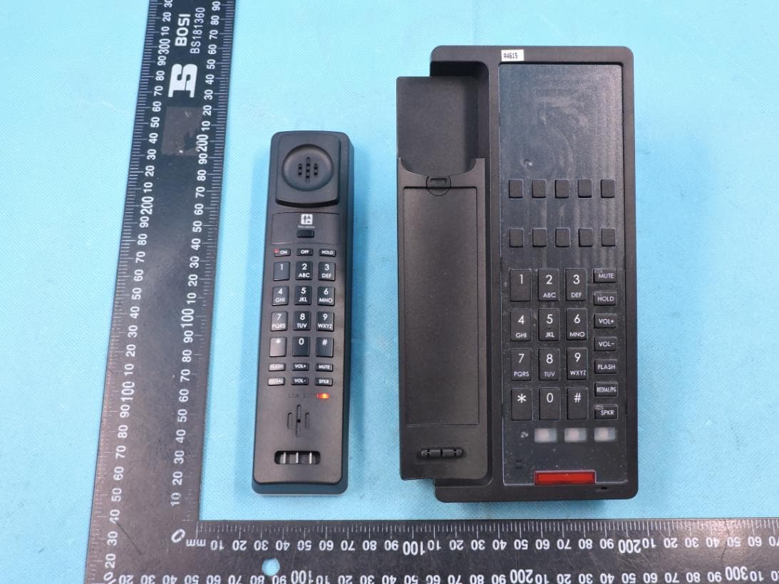
Click to zoom
Application Details
- Equipment Class
- PUB - Part 15 Unlicensed PCS Base Station
- Date of Grant
- Aug 19, 2020
- Application Purpose
- Original Equipment
- Date of Application
- Aug 18, 2020
- Equipment Note
- SIP PHONE
- Frequency Range
- 1921.53600000 - 1928.44800000
- Country
- China
Documents & Files
Document Text
Text extracted from the exhibit documents filed with the FCC. Open a document above to read the original.
Users Manual
User Manual For HWD9888(62)TSD-IP Please read this manual before use. We bring good things to Hotel/Hospitality Product overview HWD9888(62)TSD-IP is 1 line SIP cordless phone, which is specially designed for top grade hotels’ telecommunication. It has clear sound, stable quality, powerful function and elegant design, etc. It’s also a kind of SIP phone which transmits voice over network based on IP protocol. Main Features 1. The Base and Handset can make/answer any calls freely. One Base can work with 1- 4 Handsets. 2. Supports SIP V2/SDP/RTP/RTCP/STUN/SNTP/ DNS/SNMPv2 protocols. 3. Supports IEEE802.1 Q standard, IEEE802.3af protocols. 4. Supports G.711/G.722(HD Voice)/G.723/G.729AB /G.726/iLBC 5. Support 1.8/1.9Ghz, DECT6.0 and adopts HF numerical coding technical between Base and Handsets. 6. Mute, hold, flash, redial and Speaker feature 7. Message waiting light compatible with main PBX, MWL indicator and withdraw feature 8. Owns ten (10 ) service keys 9. Both Base volume and Handset volume are in five-level control 10. Supports DHCP and static IP address protocol for getting IP address. 11. Support upgrade through HTTP/TFTP protocol. 12. Adopts dynamic speech detection; Comfortable noise generation; Speech buffering technologies. 13. Integrated PoE power supply and external POE adapter power supply. 14. For HWD9888(62)TSD-IP,One of the handset is corded Installation 1. Please put the attached chargeable batteries into the handset, pay more attention to the polarity of socket and signal ribbon cable, also need to notice the direction of the jack and the socket during install the batteries. Strictly prohibit to use the wrong polarity batteries. 2. For HWD9888(62)TSD-IP, please connect the phone handset cord 3. Power by POE: Connect the output end to the WAN port of the phone and connect the input end to the Internet cable from hotel edge switch POE port. 4. Power by adaptor (The default is POE) Please connect the 9V power adapter to the DC power input, which is in the rear of the phone; connect the Internet cable to WAN port of the phone, and connect the Internet cable to the LAN port of Data port/access point. 5. Please install the phone in dry and clean environment and avoid effected with damp. 6. The telephone should avoid fire, water spray, shock, clean the surface dust by soft cloth; chemical solvent is prohibited to use. Location and Control 1 2 ABC 4 G HI 5 J KL 6 MNO PQ RS 8 TUV WXYZ 3 DEF 9 7 * 0 # MUTE HO LD VO L+ VO L - FLASH SPKR www.bittelphone.com FLASH VO L+ MUTE REDIAL VO L SPKR ON O FF HO LD 2 ABC 8 TUV 3 DEF 1 5 J KL 6 MNO 4 G HI 7 PQ RS 9 WXYZ # 0 * - IN USE C HARG E 1 2 3 2 4 2 6 1 5 3 ON O FF HO LD 1 2 ABC 3 DEF 4 G HI 5 J KL 6 MNO 7 PQ RS 8 TUV 9 WXYZ * 0 # FLASH VO L+ MUTE VO L - SPKR LO W BATT 7 1 2 ABC 4 G HI 5 J KL 6 MNO PQ RS 8 TUV WXYZ 3 DEF 9 7 * 0 # MUTE HO LD VO L+ VO L - FLASH SPKR www.bittelphone.com IN USE 4 2 6 1 5 3 1 2 3 2 ON O FF HO LD 1 2 ABC 3 DEF 4 G HI 5 J KL 6 MNO 7 PQ RS 8 TUV 9 WXYZ * 0 # FLASH VO L+ MUTE VO L - SPKR LO W BATT 9 7 8 1.Service Keys 2.Function Keys 3.Number Keys 4. DC Jack 5. WAN Port 6.LAN Port 7. Message Waiting Light 8. Handset Jack 9. TO TEL Port Configure the phone through WEB Interface 1. IP address broadcast Off-hook status, continually press * button four times will enter the voice menu. Press 1 (network setting) then press 2 (WAN port IP address), the obtained IP address will be broadcast. 2. WEB interface Input the obtained IP address to launch WEB interface . Type in user and password to log in WEB interface. 3. Launch WEB interface Input the obtained IP address to launch WEB interface . Type in user and password to log in WEB interface. Note: 1) Both the user name and password in initial management mode are ‘admin’. 2) The default network mode is DHCP. Once the phone is connected into the network environment with DHCP service, it can get online automatically 4. WEB interface function description 4.1 Phone status Product Information It shows the basic information of the product. Line Status It shows the registration state of each line. Network Status It shows the information of Internet Port WIFI and PC port. Wireless Info It shows the current WIFI setting and status. System Status It shows the current time and the running time of the product. 4.2 Network status Telephone can obtain IP address from DHCP server in default mode. Enter WEB interface to configure all related settings in accordance with real network environment. WAN IP Mode Select WAN port IP address obtainment modes including static/ DHCP/ PPPoE/ Bridge. MAC Address Clone Enable MAC address clone or not NAT Enable Activate NAT function or not. VLAN Mode Activate VLAN mode or not VLAN ID Set VLAN ID DNS Mode If DNS mode is Manual, user needs to set primary DNS and secondary DNS manually. If DNS mode is Auto, IP phone will obtain primary DNS and secondary DNS from DHCP server automatically. Primary DNS The Primary DNS setting Secondary DNS The optional DNS setting IP Address The network port IP address Subnet Mask The network port subnet mask Default Gateway The network port default gateway Note: 1) When telephone IP address is switched from DHCP to static mode, all parameters such as IP address, Subnet Mask, Default Gateway and DNS need to be set manually. 2) Save and apply switched IP address settings and reboot the phone for new IP address obtainment. Make sure the network is normal during daily using. 4.3 SIP Account Setting Phone regular usage ,only need to configure Proxy Server, Display Name , Phone Number, Account, Password. Basic Set basic information from VoIP service supplier,like phone number, account, password, SIP proxy, and etc. Audio Configuration Select audio format Supplementary Service Subscription Auxiliary function Call Waiting Enable call waiting or not Hot Line Set hot line MWI Enable Enable MWI or not Voice Mailbox Numbers Voice Mailbox server MWI Subscribe Enable Support MWI subscription 4.4 Administration Client can set password, …
Text truncated - open the document above for the full version.
Cover Letter(s)
Shandong Bittel Intelligent Technology Co.,Ltd. TCBJ FORM-4 Issued by: TCB Administrator Revision 6 12/06/10 2020-08-13 MET Laboratories, Inc. 914 West Patapsco Avenue Baltimore, MD 21230 RE: LETTER OF AGENT AUTHORIZATION To Whom It May Concern: We, Shandong Bittel Intelligent Technology Co.,Ltd. hereby authorize (Shenzhen STS Test Services Co., Ltd.) to act on our behalf in all matters relating to application for equipment authorization, including the signing of all documents relating to these matters. We also hereby certify that no party to the application authorized hereunder is subject to the denial of benefits, including FCC benefits, pursuant to Section 5301 of the Anti-Drug Abuse Act of 1988, 21 U.S.C.853(a). This agreement expires one year from the current date. Sincerely, Name: TIAN XIAOBO Signature:
Cover Letter(s)
Shandong Bittel Intelligent Technology Co.,Ltd. TCBJ FORM-4 Issued by: TCB Administrator Revision 6 12/06/10 2020-08-13 MET Laboratories, Inc. 914 West Patapsco Avenue Baltimore, MD 21230 RE: CONFIDENTIALITY REQUEST FOR ( SIP PHONE/FCC ID: 2ASTDHWD988862TSD) To Whom It May Concern: This letter serves as an official request for confidentiality under sections 0.457 and 0.459 of CFR 47. We have requested that the • Schematics • Block diagram • Operation description These materials contain trade secrets and proprietary information and are not customarily released to the public. The public disclosure of this information might be harmful to the company and provide unjustified benefits to our competitors. required to be submitted with this application be permanently withheld from public review. Please contact me if there is any information you may need. Sincerely, Name: TIAN XIAOBO Signature:
External Photos
Page 1 of 4 Report No.: STS2003210 APPENDIX-PHOTOGRAPHS OF EUT CONSTRUCTIONAL DETAILS Model: HWD9888(62)TSD-IP Photo 1 Photo 2 Page 2 of 4 Report No.: STS2003210 Photo 3 Photo 4 Page 3 of 4 Report No.: STS2003210 Photo 5 Photo 6 Page 4 of 4 Report No.: STS2003210 Photo 7 Photo 8
ID Label/Location Info
FCC Label SIP PHONE Model: HWD9888(62)TSD-IP FCC ID: 2ASTDHWD988862TSD L*H:35*40mm Screen printing
Internal Photos
Page 1 of 6 Report No.: STS2003210 APPENDIX-PHOTOGRAPHS OF EUT CONSTRUCTIONAL DETAILS Model: HWD9888(62)TSD-IP Photo 1 Photo 2 TX Antenna Page 2 of 6 Report No.: STS2003210 Photo 3 Photo 4 Page 3 of 6 Report No.: STS2003210 Photo 5 Photo 6 Page 4 of 6 Report No.: STS2003210 Photo 7 Photo 8 Page 5 of 6 Report No.: STS2003210 Photo 9 Photo 10 Page 6 of 6 Report No.: STS2003210 Photo 11
RF Exposure Info
RF Exposure Report FCC ID: 2ASTDHWD988862TSD RF Exposure Measurement The limit for Maximum Permissible Exposure (MPE) specified in FCC 1.1310 is followed. The gain of the antennas used in the product is extracted from the Antenna data sheets provided and also the maximum total power input to the antenna is measured. Through the Friis transmission formula and the maximum gain of the antenna, we can calculate the distance, away from the product, where the limit of MPE is reached. Although the Friis Transmission formula is far field assumption, the calculated result of that is an over-prediction for near field power density. It is taken as worst case to specify the safety range. RF Exposure Limit According to FCC 1.1310: The criteria listed in the following table shall be used to evaluate the environmental impact of the human exposure to radio-frequency (RF) radiation as specified in 1.1307 (b) Limits for Maximum Permissible Exposure (MPE) F= Frequency in MHz Frequency Range (MHz) Electric Field Strength (V/m) Magnetic Field Strength (A/m) Power Density (mW/cm²) Limits for Occupational / controlled Exposures 300 - 1500 -- -- F/300 1500 – 100000 -- -- 5.0 Limits for General population / Uncontrolled Exposure 300 - 1500 -- -- F/1500 1500 – 100000 -- -- 1.0 Friss Formula Friss Transmission Formula: Pd = (Pout * G) / (4*pi*r²) Where Pd = power density in mW/cm² Pout = output power to antenna in mW G = gain of antenna in linear scale Pi = 3.1416 R = Distance between observation point and the center of radiator in cm If we know the maximum gain of the antenna and the total output power to the antenna, through calculation, we will know MPE value at distance 20cm. EUT Operation condition EUT was enabled to transmit and receive at lowest, middle and highest channels. Classification The antenna of this product, under normal use condition, is at least 20cm away from the body of the user. Warning statement to the user for keeping at least 20cm or more separation distance from the antenna should be included in the User manual. So, this device is classified as Mobile device. DECT Worst Case Mode GFSK Detector PEAK 1921.536MHz 6±1dBm 1924.992MHz 6±1dBm 1928.448MHz 6±1dBm Remark: The worst case gain of the antenna is 0dBi. 0dBi logarithmic terms convert to numeric result is nearly 1.0 Protocol ANT Gain (gain of antenna in linear scale) Channel Frequency (MHz) Output Power to Antenna (dBm) Output Power to Antenna (mW) Power Density (mW/cm²) Limit (mW/cm²) GFSK 1.0 1.921536 7.0 5.01 0.000997 1 GFSK 1.0 1.924992 7.0 5.01 0.000997 1 GFSK 1.0 1.928448 7.0 5.01 0.000997 1 Threshold at which no SAR required is 0.000997≤1 mW/cm².
Test Report
Any reproduction of this document must be done in full. No single part of this document may be reproduced without permission from STS, All Test Data Presented in this report is only applicable to presented Test sample. Shenzhen STS Test Services Co., Ltd. A 1/F, Building B, Zhuoke Science Park, No.190 Chongqing Road, HepingShequ, Fuyong Sub-District, Bao’an District, Shenzhen, Guang Dong, China TEL: +86-755 3688 6288 FAX: +86-755 3688 6277 E-mail:[email protected] RADIO TEST REPORT Report No.: STS2003210W01 Issued for Shandong Bittel Intelligent Technology Co.,Ltd. No.1 Rizhao N Rd, Rizhao, Shandong, P.R.China Product Name: SIP PHONE Brand Name: N/A Model Name: HWD9888(62)TSD-IP Series Model: HWD9888TSD,HWD9888T,HWD9888(HT20D)T, HWD9888(HS20D)T,HWD9888(HT60D)TSD, HWD9888(62)TSD,HWD9888(7715)T, HWD9888(7715M)T,HWD9888(7715ZJ)T, HWD9888(77)TSD,HWD9888(BT6560)T, HWD9888(38)TSD,HWD9888TSD-IP, HWD9888T-IP,HWD9888(IP20D)T-IP, HWD9888(IP60D)TSD-IP, HWD9888(77)TSD-IP,HWD9888(7715)T-IP, HWD9888(BT6570)T-IP,HA9888TSD-IP, HA9888T-IP,HA9888(IP20-F)T-IP, HA9888(IP60-F)TSD-IP,HA9888(62)TSD-IP, HA9888(7715)TSD-IP,HA9888(7713)TSD-IP, HA9888(7711)TSD-IP,HA9888(7721)TSD-IP FCC ID: 2ASTDHWD988862TSD S T L A B S 2 of58Report No.: STS1504068F01 Test Standard: Title 47 of the CFR, Part 15 Subpart D Page 3 of 58 Report No.: STS2003210W01 TEST RESULT CERTIFICATION Applicant’s Name ................. : Shandong Bittel Intelligent Technology Co.,Ltd. Address ................................. : No.1 Rizhao N Rd, Rizhao, Shandong, P.R.China Manufacture's Name ............ : Shandong Bittel Intelligent Technology Co.,Ltd. Address ................................. : No.1 Rizhao N Rd, Rizhao, Shandong, P.R.China Product Description Product Name ........................ : SIP PHONE Model Name .......................... : HWD9888(62)TSD-IP Series Model .......................... : HWD9888TSD,HWD9888T,HWD9888(HT20D)T, HWD9888(HS20D)T,HWD9888(HT60D)TSD, HWD9888(62)TSD,HWD9888(7715)T, HWD9888(7715M)T,HWD9888(7715ZJ)T, HWD9888(77)TSD,HWD9888(BT6560)T, HWD9888(38)TSD,HWD9888TSD-IP,HWD9888T-IP, HWD9888(IP20D)T-IP,HWD9888(IP60D)TSD-IP, HWD9888(77)TSD-IP,HWD9888(7715)T-IP, HWD9888(BT6570)T-IP,HA9888TSD-IP, HA9888T-IP,HA9888(IP20-F)T-IP, HA9888(IP60-F)TSD-IP,HA9888(62)TSD-IP, HA9888(7715)TSD-IP,HA9888(7713)TSD-IP, HA9888(7711)TSD-IP,HA9888(7721)TSD-IP Test Standards ..................... : Title 47 of the CFR, Part 15. Subpart D Test procedure ........................... : ANSI C63.17-2013 This device described above has been tested by STS and the test results show that the equipment under test (EUT) is in compliance with the FCC requirements. And it is applicable only to the tested sample identified in the report. This report shall not be reproduced except in full, without the written approval of STS, this document only be altered or revised by STS, personal only, and shall be noted in the revision of the document. Date of Test ........................................... : Date of receipt of test item ...................... : 16 Mar. 2020 Date of performance of tests .................. : 16 Mar. 2020 ~10 Apr. 2020 Date of Issue .......................................... : 13 Apr. 2020 Test Result .............................................. : Pass Page 4 of 58 Report No.: STS2003210W01 Testing Engineer : (Chris Chen) Technical Manager : (Sean she) Authorized Signatory : (Vita Li) Page 5 of 58 Report No.: STS2003210W01 TABLE OF CONTENTS Page 1 INTRODUCTION 9 1.1 TEST FACTORY 9 1.2 MEASUREMENT UNCERTAINTY 9 2 PRODUCT INFORMATION 10 3 TEST CONFIGURATION OF EQUIPMENT UNDER TEST 11 3.1 DESCRIPTION OF NECESSARY ACCESSORIES AND SUPPORT UNITS 11 4 MEASUREMENT INSTRUMENTS 12 5 TEST ITEMS 13 5.1 ANTENNA REQUIREMENT 13 5.2 MODULATION TECHNIQUES 13 5.3 EMISSION BANDWIDTH 14 5.4 PEAK TRANSMIT POWER 17 5.5 POWER SPECTRAL DENSITY 19 5.6 POWER ADJUSTMENT FOR ANTENNA GAIN 23 5.7 AUTOMATICALLY DISCONTINUE TRANSMISSION 24 5.8 SYSTEM ACKNOWLEDGE-MENT TEST 25 5.9 MONITORING THRESHOLD 26 5.10 DURATION OF TRANSMISSION 27 5.11 SELECTED CHANNEL CONFIRMATION, POWER ACCURACY, SEGMENT OCCUPANCY 28 5.12 RANDOM WAITING 30 5.13 MONITORING REQUIREMENTS 31 5.14 MONITORING ANTENNA 32 5.15 DUPLEX CONNECTIONS 32 5.16 ALTERNATIVE MONITORING INTERVAL FOR CO-LOCATED DEVICES 33 5.17 FAIR ACCESS 33 5.18 SPURIOUS EMISSIONS 34 5.19 FRAME PERIOD 42 5.20 FREQUENCY STABILITY 43 5.21 CONDUCTED EMISSION MEASUREMENT 45 5.22 RADIATED SPURIOUS EMISSION 49 Page 6 of 58 Report No.: STS2003210W01 Revision History Rev. Issue Date Report NO. Effect Page Contents 00 13 Apr. 2020 STS2003210W01 ALL Initial Issue Page 7 of 58 Report No.: STS2003210W01 SUMMARY OF TEST RESULTS Test procedures according to the technical standards: The following tests were conducted on a sample of the equipment for the purpose of demonstrating com- pliance with Part 15 Subpart D. Requirement FCC Part Test Procedure Result Emission Bandwidth 15.323 (a) 6.1.3 Compliant Labeling Requirements 15.19(a)(3) -- Compliant Conducted Emissions 15.315 & 15.207 ANSI C63.4 Compliant Antenna Requirements 15.317 & 15.203 Declaration Compliant Use digital modulation 15.319 (b) 6.1.4 Compliant Peak transmit power 15.319 (c) 6.1.2 Compliant Power spectral density 15.319 (d) 6.1.5 Compliant Power adjustment for antenna gain 15.319 (e) 4.3.1 Compliant Automatically dis- continue trans- mission 15.319 (f) -- Compliant Spurious emissions conducted 15.323 (d) (1) & 15.323 (d) (2) 6.1.6 Compliant RF Exposure 15.319 (i) & 1.1307(b), 2.1091 and 2.1093 ANSI/IEEE C95.1 Compliant (The test data please refer to RF exposure and RSS102 ANNEX C report) Monitoring time 15.323 (c)(1) 7.3.4 Compliant Monitoring thresh- old 15.323 (c)(2) 7.3 Compliant Duration of transmission 15.323 (c)(3) 8.2.2 Not Applicable System acknowledgment test 15.323(c)(4) 8.2.1 Compliant Channel confirmation, Power accuracy, Segment occupancy 15.323 (c)(5) 7.3.3 & 7.3.4 Compliant Page 8 of 58 Report No.: STS2003210W01 Random waiting 15.323 (c)(6) 8.1.3 Not Applicable M…
Text truncated - open the document above for the full version.
Test Setup Photos
Page 1 of 2 Report NO.: STS2003210 PUB Setup Photo Model: HWD9888(62)TSD-IP Conducted Emission Radiated Spurious Emission(Below 1GHz) Page 2 of 2 Report NO.: STS2003210 Radiated Spurious Emission (Above 1GHz )
Contact Information
Applicant
TIAN XIAOBO(Manager)
Technical Contact
Shenzhen STS Test Services Co., Ltd.Bovey Yang
[email protected]86-0755 36886288
A 1/F, Bldg B, Zhuoke Science Park, No.190 · Baoan District, Shenzhen, Guangdong · China
Test Firm
SHENZHEN STS TEST SERVICES CO.,LTD.Bovey Yang
[email protected]+86 755-36886288
Technical Specifications
| # | Rule Parts | Frequency Range | Power Output |
|---|---|---|---|
| 1 | 15D | 1.92 GHz - 1.93 GHz | 4.68 mW |