2ASVO7C-73FM transmitter
Guangzhou Chuanzhou Electronic Technology co., Ltd
Click to zoom
Application Details
- Equipment Class
- TBC - Licensed Broadcast Station Transmitter
- Date of Grant
- Nov 23, 2020
- Application Purpose
- Original Equipment
- Date of Application
- Nov 23, 2020
- Equipment Note
- FM transmitter
- Frequency Range
- 87.90000000 - 91.90000000
- Country
- China
Documents & Files
Document Text
Text extracted from the exhibit documents filed with the FCC. Open a document above to read the original.
Users Manual
- 1 - CZE-7C INSTRUCTIONS 1.Precautions for Use ●Ensure that the power supply voltage is within the extent permitted ●Maintenance can only be professional and technical personnel to operate ●Do not touch the antenna after the transmitter is powered ●Do not boot the machine before the antenna is connected ●Do not use in an explosive environment (such as gas stations, gas, steam, etc.) ●Do not place the transmitter in extremely dusty, humid, high temperature to use ●Please be sure to use complying with local radio regulatory agencies require 2.Product Features 1. High-fidelity high stability: Motherboard is adopted by next-generation integrated NC FM stereo radio transmitter chip the BH1415 from Japan ROHM Company, built-in PLL frequency PLL, audio pre-emphasis, limiter and low pass filter circuit to achieve high fidelity, high stability signal transmission 2. Stereo clear sound: the control panel is consisted of AT89C2051 and AT24C02; after the stage by two 2SC3355 and one 2SC2053 total of three power amplifier to ensure that the three-dimensional sound quality output effect 3. Good shielding: Structure design closely, not because of external signal induction frequency drift 4. Excellent heat dissipation: The stability of the chassis using high quality aluminum alloy material, lightweight and excellent heat dissipation can work continuously to ensure that equipment 5. Easy to use: Panel use LCD to display the transmission frequency, according to the identification of the interface to connect to other hardware, easy to adjust and it is intuitive 6. Switching frequency: Can arbitrarily set from 87.9M to 91.9M range from 87.9M to 90M 90M to 91.9M, 87.9M to 91.9M 7. This subsection is with a microphone and volume control 3.Circuit Principle Stereo audio via 3.5 mm interface input, after the adjustment of the potentiometer control input to BH1415 internal, internal after pre-emphasis circuit, limiting circuit and low-pass filter circuit and by 13, 14 feet again after access to the 7.6 MHz crystal vibration frequency oscillation circuit through 200 points after the 38 KHZ subcarrier signal, and 38 KHZ subcarrier by 2 points in the frequency of 19 KHZ pilot signal modulation.Firstly, the audio signal and the 38KHz subcarrier signal are balanced modulated by a multiplexer to produce a main signal (L+R) and a 38KHz subcarrier signal (L-R) modulated by DSB, and then the composite signal with the 19KHz pilot signal is output from the 5th leg.The microphone audio is also input by another 3.5mm interface, and after audio amplification, it is combined with the composite signal output from the 5th pin. The two channels are directly modulated by a high-frequency oscillator composed of a variogram diode.Frequency control by touch the key and the MCU control the internal PLL circuit to stabilize the transmission frequency.After two stages of power amplification, the transmitting frequency generates 800MW power input to - 2 - the final amplifier RD06, which generates about 7W power output. Then, after filtering out the frequency multiplier signal through a low-pass filter composed of LC, it is transmitted to the antenna for transmission.The MCU then transmits the current transmission frequency information to the user in real time through the LCD display module. 4.Product Configuration NO. Product name specification quantity unit 1 Host machine CZE-7C 1 piece 2 antenna 1 set 3 Power adapter DC 12V/1.67A 1 set 4 Audio cable 3.5mm audio cable 1 piece 5 manual e-instruction manual 1 copy 5.Operating Instructions Front panel and rear panel front panel ① volume adjustment ⑤ Frequency down ② volume input ⑥ Microphone input ③ turn on/of ⑦ Microphone adjustment ④ Frequency increases rear panel - 3 - The transmitter operate with a omnidirectional antenna and the output power of the transmitter is less than 10W, so it can be deemed to comply with the antenna requirements of 73.316. The antenna gain shall not exceed 2.5 dBi. Audio volume and microphone adjustment frequency adjustment - 4 - power adjustment The output power of the machine in two stages: High-power file (H): >7W; Low power file (L): <1W Turn off the power adapter, disconnect the transmitter power finish line state to follow these steps: 1. First press and hold the power switch【】 ,and connect the power (DC 12V) to the antenna, after 3 seconds after release the key, at this time into the power adjustment status, the LCD display shows "L" or "H" (default image file H high power) 2. Press【▲】 , and set it as high power (H) 3. Press【▼】, and set it as low power (L) 4. Select the desired power profile, and press【】 .power setting finished, and it will into frequency range setting state. Frequency range setting (1) After the power setting, it will enter the frequency range setting state, power setting is completed, press the LCD screen display shows a set of frequencies, the frequency data is the high-end of the operating band (below) - 5 - (Factory default frequency is 91.9MHZ) (2) For example, to set the operating frequency range of 90MHz to 91MHz, then through the key【▲】【▼】 , adjust the frequency data as 91.00MHz (3) Band after the completion of the high-end setting, press key【】, the band will enter the low-end setting, LCD displayed data band low frequency (below), through key【▲】 【▼】to adjust the data to 90.00MHz Then press key【】, at this time the setting finished. (Note that the low-end band must not be higher than the high-end band.) Product Technical Parameter 1 Working voltage 11~13V DC 2 Worknig current 1.67A 3 Frequency domain 87.9-91.9MHz 4 Frequency stability ± 10PPM 5 Stepped frequency 200KHZ 6 The operating temperature of the environment 10 °C ~+50 °C 7 Outptu impedance 50 Ω 8 RF power output range H:7W (L:1W) - 6 - 9 Harmonic and noise radiation ≤-60dB 1 0 Audio distortion <0.30% 1 1 Frequency response 50HZ~15000HZ 1 2 Preemphasis delay 50us 1 3 1 3 Degree of separation ≥35dB 1 4 Input level ≤15dB 1 5 Modulation frequency deviation ± 75K…
Text truncated - open the document above for the full version.
Cover Letter(s)
Guangzhou Chuanzhou Electronic Technology co., Ltd Nov. 17, 2020 Office of Engineering Technology Federal Communications Commission 7435 Oakland Mills Road Columbia, MD 21046 USA Subject: Explanation of differences between product types FCC ID : 2ASVO7C-73 Model Number: CZE-7C, FMUSER FU-7C, SIGNSTEK ST-7C To Whom It May Concern: We, The Guangzhou Chuanzhou Electronic Technology Co., Ltd. hereby declare that the model : FMUSER FU-7C, SIGNSTEK ST-7C is identical with the model : CZE-7C, except the model names and the color of appearance. Except for the different above, no other modification is performed. Sincerely, Signature: Guangzhou Chuanzhou Electronic Technology Co., Ltd. Contact person: Anne Hu
Cover Letter(s)
Guangzhou Chuanzhou Electronic Technology Co., Ltd. Agent Authorization Company: Guangzhou Chuanzhou Electronic Technology Co., Ltd. Address: 2/F, No.3 ChuangYe Second Road, GuanDao village, ShaPu, XinTang Town, ZengCheng District, GuangZhou, China Product Name: FM transmitter Model Number(s): CZE-7C, FMUSER FU-7C, SIGNSTEK ST-7C Product Description: FM transmitter We authorize MiCOM Labs Inc., 575 Boulder Court, Pleasanton, California 94566, USA, to act on our behalf on all matters concerning the certification of above named equipment. We declare that MiCOM Labs Inc. is allowed to forward all information related to the approval and certification of equipment to the regulatory agencies as required and to discuss any issues concerning the approval application. Any and all acts carried out by MiCOM Labs on our behalf shall have the same effect as acts of our own. Signature: Date: 2020-11-17 Name: Anne Hu Company: Guangzhou Chuanzhou Electronic Technology Co., Ltd.
External Photos
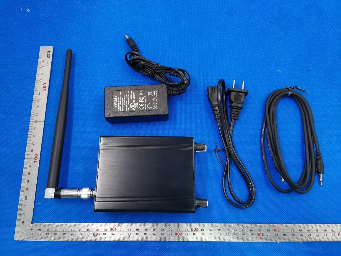
External Photos Test model: CZE-7C ALL VIEW OF EUT TOP VIEW OF EUT Antenna BOTTOM VIEW OF EUT FRONT VIEW OF EUT BACK VIEW OF EUT LEFT VIEW OF EUT RIGHT VIEW OF EUT PORT VIEW OF EUT-1 PORT VIEW OF EUT-2 PORT VIEW OF EUT-3 PORT VIEW OF EUT-4 Series model: FMUSER FU-7C ALL VIEW OF EUT TOP VIEW OF EUT BOTTOM VIEW OF EUT FRONT VIEW OF EUT BACK VIEW OF EUT LEFT VIEW OF EUT RIGHT VIEW OF EUT Series model: SIGNSTEK ST-7C ALL VIEW OF EUT TOP VIEW OF EUT BOTTOM VIEW OF EUT FRONT VIEW OF EUT BACK VIEW OF EUT LEFT VIEW OF EUT RIGHT VIEW OF EUT
ID Label/Location Info
FCC ID Label Location FCC ID: 2ASVO7C-73
Internal Photos
Internal Photos OPEN VIEW OF EUT-5 INTERNAL VIEW OF EUT-1 INTERNAL VIEW OF EUT-2 INTERNAL VIEW OF EUT-3 INTERNAL VIEW OF EUT-4 INTERNAL VIEW OF EUT-5 INTERNAL VIEW OF EUT-6 INTERNAL VIEW OF EUT-7 INTERNAL VIEW OF EUT-8
RF Exposure Info
RF EXPOSURE EVALUATION 1. TEST RESULT CERTIFICATION Applicant Guangzhou Chuanzhou Electronic Technology Co., Ltd. Address 2/F (Building C-1), No. 3, Chuangye 2nd Road, Guandao Village, Shapu, Xintang Town, Zengcheng, Guangzhou City manufacturer Guangzhou Chuanzhou Electronic Technology Co., Ltd. Address 2/F (Building C-1), No. 3, Chuangye 2nd Road, Guandao Village, Shapu, Xintang Town, Zengcheng, Guangzhou City Factory Guangzhou Chuanzhou Electronic Technology Co., Ltd. Address 2/F (Building C-1), No. 3, Chuangye 2nd Road, Guandao Village, Shapu, Xintang Town, Zengcheng, Guangzhou City Product Designation: FM transmitter Brand Name: CZERF Test Model: CZE-7C FCC ID: 2ASVO7C-73 Date of Test: Oct. 10, 2020 to Nov. 05, 2020 2. TECHNICAL INFORMATION A major technical description of EUT is described as following: Operation Frequency 87.9MHz-91.9MHz Modulation FM Antenna Designation Dedicated Antenna Antenna type External antenna Hardware Version V2.3 Software Version V1.4 Maximum Conducted Power 7.06W Antenna gain 2.5dBi Power Supply INPUT: 100-240V~ 50-60Hz 0.6A OUTPUT: 12V⎓1.67A 3. RF EXPOSURE MEASUREMENT 3.1 INTRODUCTION Human exposure to RF emissions from mobile devices (47 CFR §2.1091) may be evaluated based on the MPE limits adopted by the FCC for electric and magnetic field strength and/or power density, as appropriate, since exposures are assumed to occur at distances of 20 cm or more from persons. The 1992 ANSI/IEEE standard (See Listed limit table) specifies a minimum separation distance of 20 cm for performing reliable field measurements to determine adherence to MPE limits. If the minimum separation distance between a transmitter and nearby persons is more than 20 cm under normal operating conditions, compliance with MPE limits may be determined at such distance from the transmitter. When applicable, operation instructions and prominent warning labels may be used to alert the exposed persons to maintain a specified distance from the transmitter or to limit their exposure durations and usage conditions to ensure compliance. 3.2 FCC LIMITS FOR MAXIMUM PERMISSIBLE EXPOSURE (MPE) Note: 1. f= Frequency in MHz * Plane-wave Equivalent Power Density 2.The averaging time for General Population/Uncontrolled exposure to fixed transmitters is not applicable for mobile and portable transmitters. See 47 CFR §§2.1091 and 2.1093 on source-based time-averaging requirement for mobile and portable transmitters. 4. CLASSIFICATION OF THE ASSESSMENT METHODS According to user manual, The antenna of the product, under normal use condition is at least 40 cm away from the body of the user. Warning statement to the user for keeping at least 40cm separation distance and the prohibition of operating to a person has been printed on the user’s manual. So, this product under normal use is located on electromagnetic far field between the human body. S=PG/4πR² Where: S=power density P=power input to antenna G=power gain of the antenna in the direction of interest relative to an isotropic radiator R=distance to the center of radiation of the antenna Limit : GENERAL POPULATION / UNCONTROLLED EXPOSURE Occupational/Controlled Exposure 5. EUT OPERATION CONDITION Make the EUT to transmit at Bottom channel, Middle channel and Top channel individually. 6. TEST RESULTS Antenna Gain=2.5 dBi (Numeric 1.78), π=3.141, R=40cm Frequency Output Power Tune-up Power Tune-up Power Power Density Power Density Limit Result MHz dBm dBm mW mW/cm 2 mW/cm 2 Pass/Fail 91.9 38.486 39.486 8883.825 0.7857 1.0 Pass Note: 1.The output power is refer to AGC10636201001FE04. 2. Only the worst result was recorded in this part.
Test Report
Page 1 of 60 FCC Test Report Report No.: AGC10636201001FE04 FCC ID : 2ASVO7C-73 APPLICATION PURPOSE : Original Equipment PRODUCT DESIGNATION : FM transmitter BRAND NAME : CZERF MODEL NAME : CZE-7C, FMUSER FU-7C, SIGNSTEK ST-7C APPLICANT : Guangzhou Chuanzhou Electronic Technology Co., Ltd. DATE OF ISSUE : Nov. 05, 2020 STANDARD(S) : FCC Part 73 Subpart D REPORT VERSION : V1.0 Attestation of Global Compliance (Shenzhen) Co., Ltd Report No.: AGC10636201001FE04 Page 2 of 60 REPORT REVISE RECORD Report Version Revise Time Issued Date Valid Version Notes V1.0 / Nov. 05, 2020 Valid Initial Release Report No.: AGC10636201001FE04 Page 3 of 60 TABLE OF CONTENTS 1. VERIFICATION OF CONFORMITY .......................................................................................................................... 5 2. GENERAL INFORMATION ....................................................................................................................................... 6 2.1. PRODUCT DESCRIPTION ....................................................................................................................................................... 6 3. MEASUREMENT UNCERTAINTY ............................................................................................................................ 7 4. DESCRIPTION OF TEST MODES ............................................................................................................................ 8 5. SYSTEM TEST CONFIGURATION........................................................................................................................... 9 5.1. CONFIGURATION OF EUT SYSTEM ........................................................................................................................................ 9 5.2 EQUIPMENT USED IN TESTED SYSTEM .................................................................................................................................. 9 5.3. SUMMARY OF TEST RESULTS ................................................................................................................................................ 9 6. TEST FACILITY ....................................................................................................................................................... 10 7. OUPUT POWER ...................................................................................................................................................... 11 7.1. TEST LIMIT .......................................................................................................................................................................... 11 7.2. MEASUREMENT PROCEDURE ............................................................................................................................................ 11 7.3. TEST SETUP ........................................................................................................................................................................ 12 7.4. TEST RESULT ....................................................................................................................................................................... 13 8. MODULATION CHARACTERISTICS ..................................................................................................................... 16 8.1 TEST LIMIT ........................................................................................................................................................................... 16 8.2 MEASUREMENT METHOD ................................................................................................................................................... 16 8.3. TEST SETUP ........................................................................................................................................................................ 16 8.4 TEST RESULT ........................................................................................................................................................................ 17 9. OCCUPIED BANDWIDTH ....................................................................................................................................... 19 9.1. TEST LIMIT .......................................................................................................................................................................... 19 9.2. MEASUREMENT PROCEDURE ............................................................................................................................................ 19 9.3. TEST SET-UP ....................................................................................................................................................................... 19 9.4. MEASUREMENT RESULTS ................................................................................................................................................... 20 Report No.: AGC10636201001FE04 Page 4 of 60 10. FREQUENCY STABILITY ..................................................................................................................................... 26 10.1. TEST LIMIT ........................................................................................................................................................................ 26 10.2. MEASUREMENT PROCEDURE .......................................................................................................................................... 26 10.3. TEST SET-UP ..................................................................................................................................................................... 26 10.4. TEST RESULT ..................................................................................................................................................................... 27 11. EMISSION MASK AND SPURIOUS EMISSIONS .............................…
Text truncated - open the document above for the full version.
Test Report
Report No.: AGC10636201001FE04 Page 45 of 60 BACK VIEW OF EUT LEFT VIEW OF EUT Report No.: AGC10636201001FE04 Page 46 of 60 RIGHT VIEW OF EUT PORT VIEW OF EUT-1 Report No.: AGC10636201001FE04 Page 47 of 60 PORT VIEW OF EUT-2 PORT VIEW OF EUT-3 Report No.: AGC10636201001FE04 Page 48 of 60 PORT VIEW OF EUT-4 OPEN VIEW OF EUT-5 Report No.: AGC10636201001FE04 Page 49 of 60 INTERNAL VIEW OF EUT-1 INTERNAL VIEW OF EUT-2 Report No.: AGC10636201001FE04 Page 50 of 60 INTERNAL VIEW OF EUT-3 INTERNAL VIEW OF EUT-4 Report No.: AGC10636201001FE04 Page 51 of 60 INTERNAL VIEW OF EUT-5 INTERNAL VIEW OF EUT-6 Report No.: AGC10636201001FE04 Page 52 of 60 INTERNAL VIEW OF EUT-7 INTERNAL VIEW OF EUT-8 Report No.: AGC10636201001FE04 Page 53 of 60 ADAPTER VIEW OF EUT Series model: FMUSER FU-7C ALL VIEW OF EUT Report No.: AGC10636201001FE04 Page 54 of 60 TOP VIEW OF EUT BOTTOM VIEW OF EUT Report No.: AGC10636201001FE04 Page 55 of 60 FRONT VIEW OF EUT BACK VIEW OF EUT Report No.: AGC10636201001FE04 Page 56 of 60 LEFT VIEW OF EUT RIGHT VIEW OF EUT Report No.: AGC10636201001FE04 Page 57 of 60 Series model: SIGNSTEK ST-7C ALL VIEW OF EUT TOP VIEW OF EUT Report No.: AGC10636201001FE04 Page 58 of 60 BOTTOM VIEW OF EUT FRONT VIEW OF EUT Report No.: AGC10636201001FE04 Page 59 of 60 BACK VIEW OF EUT LEFT VIEW OF EUT Report No.: AGC10636201001FE04 Page 60 of 60 RIGHT VIEW OF EUT ----END OF REPORT---- Conditions of Issuance of Test Reports 1. All samples and goods are accepted by the Attestation of Global Compliance (Shenzhen) Co., Ltd (the “Company”) solely for testing and reporting in accordance with the following terms and conditions. The company provides its services on the basis that such terms and conditions constitute express agreement between the company and any person, firm or company requesting its services (the “Clients”). 2. Any report issued by Company as a result of this application for testing services (the “Report”) shall be issued in confidence to the Clients and the Report will be strictly treated as such by the Company. It may not be reproduced either in its entirety or in part and it may not be used for advertising or other unauthorized purposes without the written consent of the Company. The Clients to whom the Report is issued may, however, show or send it, or a certified copy thereof prepared by the Company to its customer, supplier or other persons directly concerned. The Company will not, without the consent of the Clients, enter into any discussion or correspondence with any third party concerning the contents of the Report, unless required by the relevant governmental authorities, laws or court orders. 3.The Company shall not be called or be liable to be called to give evidence or testimony on the Report in a court of law without its prior written consent, unless required by the relevant governmental authorities, laws or court orders. 4. The non-CMA report issued by AGC is only permitted to be used by the client as internal reference use and shall not be used for public demonstration purpose. 5. In the event of the improper use of the report as determined by the Company, the Company reserves the right to withdraw it, and to adopt any other additional remedies which may be appropriate. 6. Samples submitted for testing are accepted on the understanding that the Report issued cannot form the basis of, or be the instrument for, any legal action against the Company. 7. The Company will not be liable for or accept responsibility for any loss or damage however arising from the use of information contained in any of its Reports or in any communication whatsoever about its said tests or investigations. 8.Clients wishing to use the Report in court proceedings or arbitration shall inform the Company to that effect prior to submitting the sample for testing. 9. The Company is not responsible for recalling the electronic version of the original report when any revision is made to them. The Client assumes the responsibility to providing the revised version to any interested party who uses them. 10. Subject to the variable length of retention time for test data and report stored hereinto as otherwise specifically required by individual accreditation authorities, the Company will only keep the supporting test data and information of the test report for a period of six years. The data and information will be disposed of after the aforementioned retention period has elapsed. Under no circumstances shall we provide any data and information which has been disposed of after retention period. Under no circumstances shall we be liable for damage of any kind, including (but not limited to) compensatory damages, lost profits, lost data, or any form of special, incidental, indirect, consequential or punitive damages of any kind, whether based on breach of contract of warranty, tort (including negligence), product liability or otherwise, even if we are informed in advance of the possibility of such damages.
Test Setup Photos
Test Setup Photos RADIATED EMISSION TEST SETUP –BELOW 1GHz RADIATED EMISSION TEST SETUP –BELOW 1GHz
Contact Information
Applicant
Anne Hu
Technical Contact
Test Firm
Attestation of Global Compliance (Shenzhen) Co., LDoris Li
[email protected]+86-755-25234088
Technical Specifications
| # | Rule Parts | Frequency Range | Power Output | Emission | Tolerance |
|---|---|---|---|---|---|
| 1 | 73 | 87.9 MHz - 91.9 MHz | 7.06 W | 149KF3E | 239.0000000000 Hz |
Other Applications from Guangzhou Chuanzhou Electronic Technology co., Ltd
2ASVO05B-73
Jul 28, 2020FM transmitter
Equipment Class
TBC - Licensed Broadcast Station Transmitter