2ASVU-U370WiFi PIR ON/OFF Switch
Shenzhen Asia Bright Industry Co., Ltd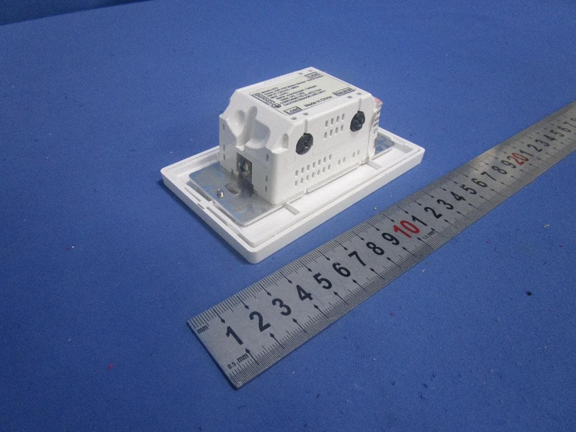
Click to zoom
Application Details
- Equipment Class
- DTS - Digital Transmission System
- Date of Grant
- May 21, 2020
- Application Purpose
- Original Equipment
- Date of Application
- May 21, 2020
- Equipment Note
- WiFi PIR ON/OFF Switch
- Frequency Range
- 2412.00000000 - 2462.00000000
- Country
- China
Documents & Files
Document Text
Text extracted from the exhibit documents filed with the FCC. Open a document above to read the original.
Users Manual
12 43 WiFi PIR ON/OFF Switch Model:u370 Http://www.a-brt.comE-mail:[email protected] Asia Bright Shenzhen Asia Bright Industry Co.,Ltd. Address : Building 10, Asia Industial Park, Gangtou, Bantian, Shenzhen , China 地址深圳市坂田岗头村亚洲工业园10栋邮编:518129 Tel : +86-755-89748200 89748211 Fax : +86-755-89748778 89748226 深圳市亚晔实业有限公司 User Manual 2.Technical Parameters: (1). Operation Voltage: AC 108~240V (2). Frequency: 45Hz~65Hz (3). Power Rating: 5W~600W (600W max for incandescent light, and 150W max for LED light) (4). PIR Sensing Range: up to 8 meters (5). PIR Sensing Angle: up to 120 degrees (when installed at 1.2m height above ground ) (6). Wireless Distance: 30 meters max communicating distance from gateway switch (7). Load Types: Incandescent lights; Halogen lamp; LED;and CFL lights. 3.Operation Guide: User can also turn on/off the load using the On/Off button. The preset delay-off function is still in effect if the load is turned on by manual operati 1.Features: Equipped with PIR Motion Sensor, u370 brings to users convenience and help users to conserve energy by automatically turning off lights when a room is not oc ON/OFF Wi-Fi indicator light PIR Sensor Reset Safety Power Switch (2).Scan the QR code in the user manual to download our Application, and add switches on the Application according to the operation guide. (1).The blue indicator will flicker 3 times after being powered on and the initialization process takes 30 seconds. After initialization process finished, the PIR sensor starts working. The switch will turn on the load automatically when it detects human motion and the ambient light is dark, and turn off the load after a preset delay-off time when it detects no human motion. (4). After Internet configuration finished, the PIR sensitivity, ambient light sensitivity, delay off timer and operation mode can be set on the Smartphone. The description of operation mode as below. (3). Set the Wi-Fi indicator to quick flashing or slow flashing: Wi-Fi indicatorto quick flash and slow flash. Press and hold the ON/OFF button to switch the Operation Mode Manual Control Mode Auto Control Mode(Default) Semi-auto Control Mode Description Manual ON, manual OFF, the PIR sensor does not control the load. Auto ON when the PIR sensor detects human motion, auto OFF when no human motion detected. Manual control is also available. After the load is turned off manually, the PIR function will stop working for 20 seconds. The PIR sensor starts working after the load is turned on manually, and turn off the load automatically when no human motion detected. 56 78 5.Installation Guide: 4.Wiring Diagram: Reorient or relocate the receiving antenna. Increase the separation between the equipment and receiver.Connect the equipment into an outlet on a circuit different from that to which the receiver is connected.Consult the dealer or an experienced radio/TV technician for help. Ground Load Neutral Line ACL ACN LOAD Ground Install the switch at a height of 1.2meters above ground. Warning: Changes or modifications to this unit not expressly approved by the party responsible for compliance could void the user’s authority to operate the equipment. NOTE: This equipment has been tested and found to comply with the limits for a Class B digital device, pursuant to Part 15 of the FCC Rules. These limits are designed to provide reasonable protection against harmful interference in a residential installation. This equipment generates, uses and can radiate radio frequency energy and, if not installed and used in accordance with the instructions, may cause harmful interference to radio communications.However, there is no guarantee that interference will not occur in a particular installation. If this equipment does cause harmful interference to radio or television reception, which can be determined by turning the equipment off and on, the user is encouraged to try to correct the interference by one or more of the following measures: lCaution: FCC Statement: This device complies with Part 15 of the FCC Rules. Operation is subject to the following two conditions: (1).this device may not cause harmful interference, and (2).this device must accept any interference received, including interference that may cause undesired operation. RF Radiation Exposure Statement Caution: To maintain compliance with the FCC’s RF exposure guidelines, place the product at least 20cm from nearby persons. Installation must be done by qualified personnel only.Follow safety procedures to avoid electric shock!
Cover Letter(s)
Shenzhen Asia Brieht Industry Co., Ltd Federal Communications Commission 44512d, Street SW Washington,Dc 20554 Subject: Limited Agency Agreement Shenzhen Asia Bright Industry Co., Ltd FCC ID: 2ASW-U370 To Whom It May Concern: We, (Shenzhen Asia Bright Industry Co., Ltd),hereby authorized Intertek Testing Services to act as our Agent for the purpose of preparing application for FCC ID number (2ASW-U370) under all applicable parts of the FCC rules and regulations. The effective date of this limited agency agreement is 2d Jan, 2020. Thelimited Agency Agreement expires on (2d Jan, 2021), unless sooner terminated or extended by wriuin notice to Intertek resting services and the Federal communications commission. This is to advise that we are in full compliance with the Anti-Drug Abuse Act. The applicant is not subject to a denial of federC benefits pursuant to Section 5301 of the Anti-Drug Ait of 1988, 21 U.S.C. 862, andno party to the application is subject to a denial of federal ben#ts pursuant to that section. If you have any questions or comments, please do not hesitate to contact me. Sincerely, Xlapr"in Y^t XaominYang Senior Engineering Manager
Cover Letter(s)
Attention: Certification reviewer RE: Request for Confidentiality FCC ID: 2ASW-U370 ToWhom ltMay Concern: X Permanent Conftdentiatity lComplete this section if permanent confidentiality is requestedl Request. to withhold permanently from public review certain portions of the application for equipment certification for the referenced FCC identifiers. This request for confidentiality is made pursuant to 47 CFR 0.457(d) and 0.459 of the FCC Rules. In particular, the following sections of the application are to be kept permanently confi dential : lSelect one or more of items below, as appropriate) X Schematics X BlockDiagrams X OperationalDescription E Tune-upProcedure E Parts List I iriei*iphotos (see note) I Users Manual (see note) Note 1 : Intemal Photos may be held confidential I ) if the circuit board or internal components are not accessible to users. For example, it is acceptable ifthe circuit board is enclosed in epoxy. 2) Also, it is acceptable ifthe device is not accessible to the public, for example, a device mounted on the top ofa large tower (or in a fenced enclosure) such .r that it is only serviceable by professional designated technicians under a Non-Disclosure Agreement (NDA). All sales for these devices must be under a NDA restricting the disclosure ofthe propriety informatiorl including intemal photos. Users Manual may be held confidential only when the manual contains proprietary technical information intended for professional technicians obligated under a NDA. All sales and distribution ofthe user's manual must be under a NDA that restricts the disclosure of the information In the application cover letter requesting permanent confidentiality the following additionat description and the NDA exhibitisrequired: r l. Describe in detail how intemal photos and/or users manual information are controlled to prevent them from becoming public or disclosed to unauthorized persons. 2. Describe how public access is restricted for products serviceable by professional designated technicians. final user of the device is subject to the NDA. 4. Provide an example ofthe NDA between the grantee and a purchaser. The request for confidentiality must Noter2: For scanning receiver, the schematics, block diagrams, operational description, tune-up procedure, parts list and intemal photos are alwa),s held permanently confidential. Z Shott-term Conftdentiality lComplete .this section if short-term conrtfunfiatity is requestedl Request to withhold from public review for a period of [please enter I to 180] days from the date of the Grant of Equipment Authorization and prior to marketing, certain portions of the application for equipment certification for the referenced FCC identifiers. This request for confidentiality is made pursuant to 47 CFR 0.457(d) and 0.459 of the FCC Rules. In particular, thafollowing sections of the application are to be kept short-term confidential for a period above from the date ofthe grant lselect one or more ofitems below that are not selected in the list above, as appropriatef E Schematics n Block diagrams I OperationalDescription E Tune-up Procedrire Parts List Test Setup Photos External Photos Internal Photos User Manual Rationale for request for confidentiality: We have invested considerable time and materials in research and development to produce the referenced product. X Permanent conJidentiaftry.' Disclosure of the permanently confidential portions of this application to competitors would not only give them significant competitive advantages in developing similar products, but would also disclose successful implementation of unpublished, leading edge technology developed by us. J Short-term coffidentiality.' Disclosure of the short-term confidential portions of this application during the period of importation and./or distribution would reveal key aspects of proprietary technolory to competitors and diminish the value of our investrnent in research and development. If you have questions or need further information, please contact the undersigned. Sincerely, /'iavw\r,-Yt*Z XiaominYang Senior Engineering Manager 2020.1.2
External Photos
External Photos
ID Label/Location Info
size: 43.2*26.5mm
Internal Photos
Internal Photos 2.4G Wi-Fi Antenna
RF Exposure Info
INTERTEK TESTING SERVICES RF Exposure The Equipment Under Test (EUT) is a WiFi PIR ON/OFF Switch with Wi-Fi function operating at 2412-2462MHz for 802.11b/g/n-HT20, 11 channels with 5MHz channel spacing. The EUT is powered by AC120V/60Hz. For more detailed features description, please refer to the user’s manual. 2.4GHz Wi-Fi: Antenna Type: Integral Antenna. Antenna Gain: 1.5dBi. Modulation Type: CCK, BPSK, QPSK, 16QAM, 64QAM, DQPSK, DBPSK. The nominal conducted output power specified: 20dBm (Tolerance: +/-3dB). The maximun conducted output power for the EUT is 22.81dBm in the frequency 2412MHz(IEEE 802.11b) which is within the production variation. The minimum conducted output power for the EUT is 22.27dBm in the frequency 2462MHz(IEEE 802.11n-HT20) which is within the production variation. According to FCC Part 2.1091, this unlicensed transmitting devices is categorically excluded from routine environmental evaluation for RF exposure prior to equipment authorization or use, According to the KDB 447498 and OET 65, the simple calculation as below: The source-based time averaged maximum radiated power = 20dBm+3dB+1.5dBi =24.5dBm = 281.8mW From above data, the exposed power density at a distance (R) of 20cm from the center of radiation of the antenna for 2.4GHz WIFI band can be calculated according to OET 65 as follow: = 281.8mW/ 4 πR^2 = 0.056 mW/cm^2 <1mW/cm^2 The MPE limit is 1.0 mW/cm^2 for general population and uncontrolled exposure in the Wi-Fi frequency range according to FCC Part 1.1310. As the measured power density at 20cm from the transmitter is lower than the MPE limit, the compliance to the MPE limit can be ensured by indicating the minimum 20cm separation between the transmitter's radiating structure and body of the user or nearby persons. The following RF exposure statement or similar sentence is proposed to be included in the user manual: “FCC RF Radiation Exposure Statement Caution: This Transmitter must be installed to provide a separation distance of at least 20 cm from all persons.” FCC ID: 2ASVU-U370
Test Report
Shenzhen Asia Bright Industry Co., Ltd TEST REPORT SCOPE OF WORK FCC TESTING–U370 REPORT NUMBER 190918041SZN-001 ISSUE DATE [REVISED DATE] 13 November 2019 [---------------------] PAGES 61 DOCUMENT CONTROL NUMBER FCC ID 247_b © 2017 INTERTEK Intertek Report No.: 190918041SZN-001 This report is for the exclusive use of Intertek's Client and is provided pursuant to the agreement between Intertek and its Client. Intertek's responsibility and liability are limited to the terms and conditions of the agreement. Intertek assumes no liability to any party, other than to the Client in accordance with the agreement, for any loss, expense or damage occasioned by the use of this report. Only the Client is authorized to permit copying or distribution of this report and then only in its entirety. Any use of the Intertek name or one of its marks for the sale or advertisement of the tested material, product or service must first be approved in writing by Intertek. The observations and test results in this report are relevant only to the sample tested. This report by itself does not imply that the material, product, or service is or has ever been under an Intertek certification program. Intertek Testing Services Shenzhen Ltd. Longhua Branch 101, 201, Building B, No. 308 Wuhe Avenue, Zhangkengjing Community, GuanHu Subdistrict, LongHua District, Shenzhen, P.R. China. Tel: (86 755) 8601 6288 Fax: (86 755) 8601 6751 Version: 01-November-2017 Page: 1 of 61 FCC ID 247_b TEST REPORT 101, 201, Building B, No. 308 Wuhe Avenue, Zhangkengjing Community, GuanHu Subdistrict, LongHua District, Shenzhen, P.R. China. Tel: (86 755) 8601 6288 Fax: (86 755) 8601 6751 www.intertek.com Shenzhen Asia Bright Industry Co., Ltd Application For Certification FCC ID: 2ASVU-U370 WiFi PIR ON/OFF Switch Model: u370 2.4GHz Wi-Fi Transceiver Report No.: 190918041SZN-001 We hereby certify that the sample of the above item is considered to comply with the requirements of FCC Part 15, Subpart C for Intentional Radiator, mention 47 CFR [ 10-1-18] Prepared and Checked by: Approved by: Winkey Wang Kidd Yang Senior Project Engineer Technical Supervisor Date: 13 November 2019 Intertek Report No.: 190918041SZN-001 Version: 01-November-2017 Page: 2 of 61 FCC ID 247_b TEST REPORT MEASUREMENT/TECHNICAL REPORT This report concerns (check one) Original Grant X Class II Change Equipment Type: DTS - Part 15 Digital Transmission Systems (Wi-Fi transmitter portion) Deferred grant requested per 47 CFR 0.457(d)(1)(ii)? Yes No X If yes, defer until : date Company Name agrees to notify the Commission by: date of the intended date of announcement of the product so that the grant can be issued on that date. Transition Rules Request per 15.37? Yes No X If no, assumed Part 15, Subpart C for intentional radiator - the new 47 CFR [10-01- 18] Edition] provision. Report prepared by: Winkey Wang Intertek Testing Services Shenzhen Ltd. Longhua Branch 101, 201, Building B, No. 308 Wuhe Avenue, Zhangkengjing Community, GuanHu Subdistrict, LongHua District, Shenzhen, P.R. China. Tel: (86 755) 8614 0684 Fax: (86 755) 8601 6661 Intertek Report No.: 190918041SZN-001 Version: 01-November-2017 Page: 3 of 61 FCC ID 247_b TEST REPORT Table of Contents 1.0 Summary of Test results ............................................................................................... 4 2.0 General Description ...................................................................................................... 5 2.1 Product Description ........................................................................................................... 5 2.2 Related Submittal(s) Grants ............................................................................................... 5 2.3 Test Methodology .............................................................................................................. 5 2.4 Test Facility ........................................................................................................................ 5 3.0 System Test Configuration ............................................................................................ 6 3.1 Justification ........................................................................................................................ 6 3.2 EUT Exercising Software ..................................................................................................... 6 3.3 Special Accessories ............................................................................................................ 6 3.4 Measurement Uncertainty ................................................................................................. 7 3.5 Equipment Modification .................................................................................................... 7 3.6 Support Equipment List and Description .......................................................................... 7 4.0 Measurement Results ................................................................................................... 8 4.1 Maximum Conducted Output Power at Antenna Terminals ................................................. 8 4.2 Minimum 6 dB RF Bandwidth ............................................................................................ 9 4.3 Maximum Power Density Reading ................................................................................... 15 4.4 Out of Band Conducted Emissions ................................................................................... 21 4.5 Out of Band Radiated Emissions ...................................................................................... 40 4.6 Transmitter Radiated Emissions in Restricted Bands ........................................................ 41 4.7 Field Strength Calculation ................................................................................................ 42 4.8 Radiated Spurious Emission ....................................................................…
Text truncated - open the document above for the full version.
Test Setup Photos
Radiated Emission (Up to 1GHz) Radiated Emission (Above 1GHz)
Test Setup Photos
Conducted photos
Contact Information
Applicant
Xiaomin Yang(Engineering Manager)
Technical Contact
Intertek Testing Services Shenzhen Ltd. Longhua BrWilliam Chen
[email protected](86 755) 8601 6288
101, 201, Block B, No. 308 Wuhe Blvd, Zhangkengjin · Shenzhen · China
Non-Technical Contact
Intertek Testing Services Shenzhen Ltd. Longhua BrWilliam Chen
[email protected](86 755) 8601 6288
Test Firm
Intertek Testing Services Shenzhen Ltd. Longhua BrHolly Ou
[email protected]+86 755 86140691
Technical Specifications
| # | Rule Parts | Frequency Range | Power Output |
|---|---|---|---|
| 1 | 15C | 2.41 GHz - 2.46 GHz | 191.00 mW |
Other Applications from Shenzhen Asia Bright Industry Co., Ltd
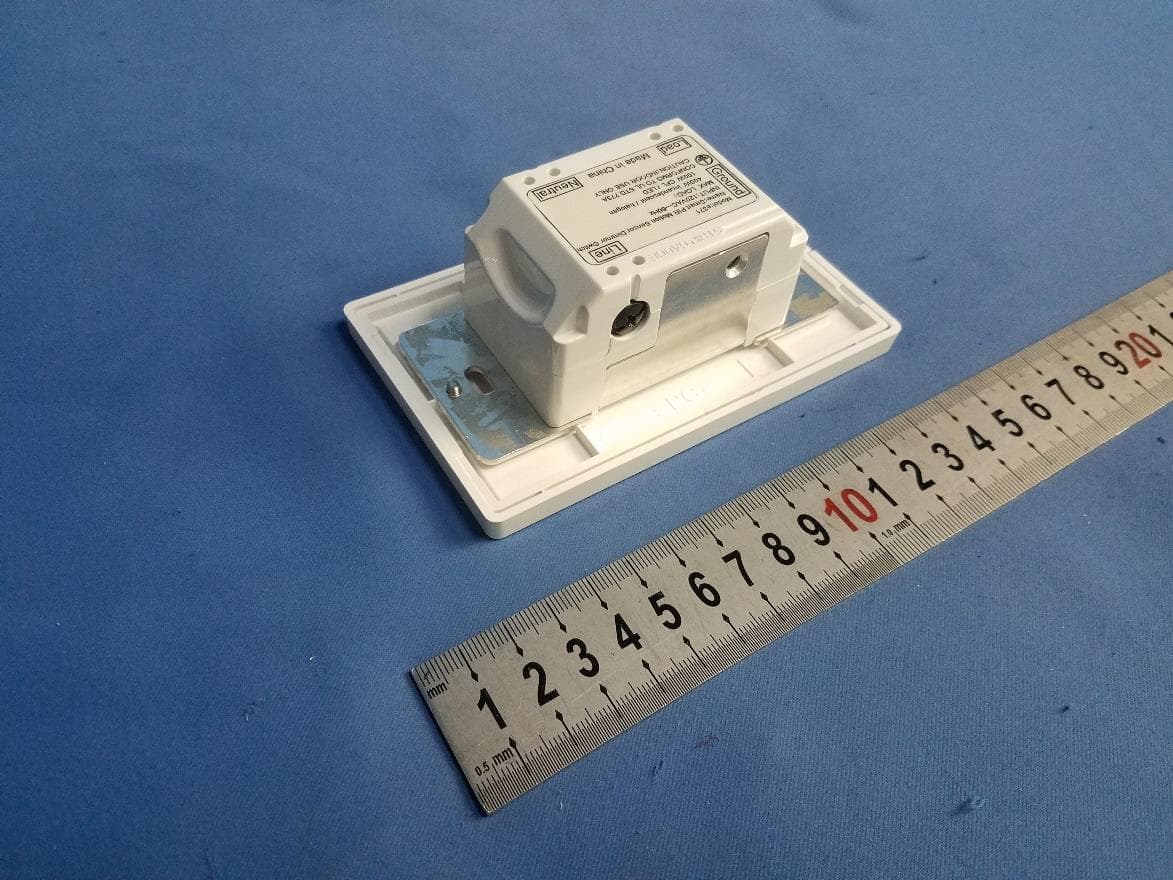
2ASVU-E371
Jul 26, 2020WiFi Gateway PIR Dimmer Switch
Equipment Class
DTS - Digital Transmission System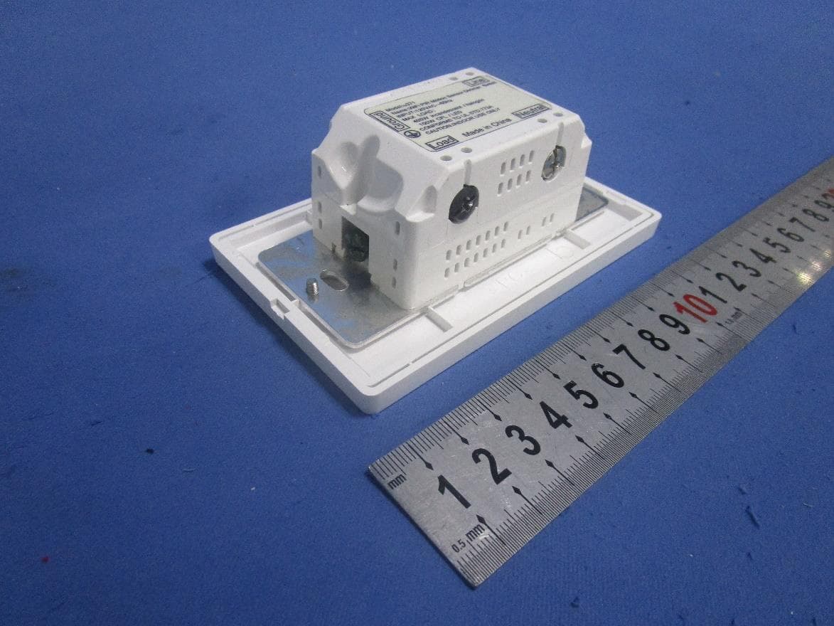
2ASVU-U371
Jul 23, 2020WiFi PIR Dimmer Switch
Equipment Class
DTS - Digital Transmission System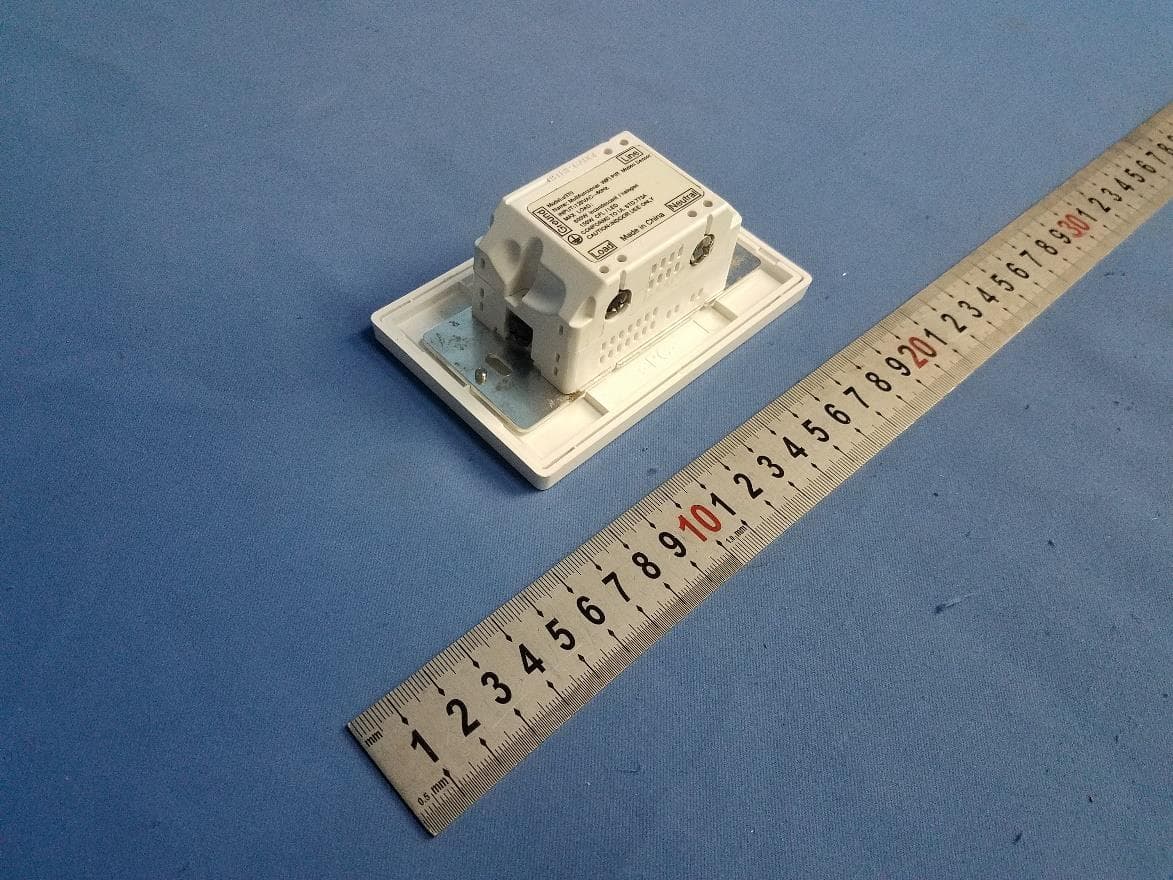
2ASVU-E370
May 20, 2020WiFi Gateway PIR ON/OFF Switch
Equipment Class
DTS - Digital Transmission System