2AT4D-Z5EA05PFCC0213.56MHz RFID Reader/Writer
B&PLUS KK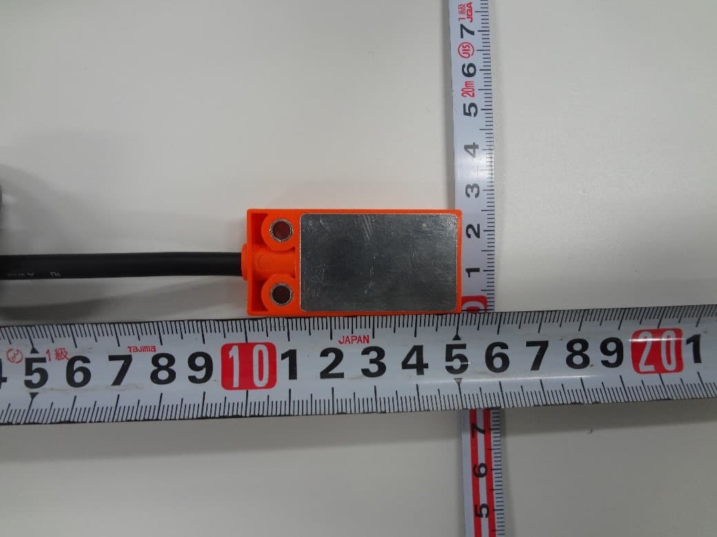
Click to zoom
Application Details
- Equipment Class
- DXX - Part 15 Low Power Communication Device Transmitter
- Date of Grant
- May 25, 2020
- Application Purpose
- Original Equipment
- Date of Application
- May 25, 2020
- Equipment Note
- 13.56MHz RFID Reader/Writer
- Frequency Range
- 13.56000000 - 13.56000000
- Company
- B&PLUS KK
- Country
- Japan
Documents & Files
Document Text
Text extracted from the exhibit documents filed with the FCC. Open a document above to read the original.
Users Manual
Issued:4.22.2020 No. T716301De Easy ID/5bit system Read System Reader Z5-EA05N-_ _ , Z5-EA05P-_ _ Z5-EA05BKN-_ _ , Z5-EA05BKP-_ _ Z5-EA05P-FCC-02 Z5-EA05BKP-FCC-02 Manual 5-bit system Reader Contents 1. Description 1.1 Description ・・・・・・・・・・・・・・・・・・・・・・・・・・・・・・・・・・・3 1.2 System configuration ・・・・・・・・・・・・・・・・・・・・・・・・・・・・・・・・・3 1.3 Each role ・・・・・・・・・・・・・・・・・・・・・・・・・・・・・・・・・・・・・・3 1.4 5bit format system ・・・・・・・・・・・・・・・・・・・・・・・・・・・・・・・・・・3 2. Specifications ・・・・・・・・・・・・・・・・・・・・・・・・・・・・・・・・・・・・・・・4 3. Installation and Wiring ・・・・・・・・・・・・・・・・・・・・・・・・・・・・・・・・・・・5 4. Communication with the External Unit ・・・・・・・・・・・・・・・・・・・・・・・・・・・8 5. Available ID tag and reading distance ・・・・・・・・・・・・・・・・・・・・・・・・・10 Safety Considerations (Please read through before use) Before using this product, please carefully read this instruction manual, pay attention to safety, and handle it properly. Design considerations ◆ This product constitutes the identification system together with the ISO 15693 compliant ID tag. Please do not use for other uses. ◆ Please design the system so that the entire system works on the safe side even if the external power supply malfunction or this product breaks down ◆ Please design the system carefully and not to exceed the range of the equipment specification described in this instruction manual for power supply / usage conditions. Usage considerations ◆ Use a regulated power supply, e.g. switch-model type. There is a risk of fire or heat generation exceeds the rated voltage power is being supplied" ◆ "When wiring the processor, follow the chapters containing the wiring diagrams closely, and wire all connections properly. Incorrectly connected wiring may cause malfunction or unexpected problems." ◆ When installing, maintaining, troubles etc. concerning this product, be sure to turn off the power, please go. ◆ Do not disassemble or modify the processor. Which may cause failure,malfunction, injury or fire. ◆ To avoid malfunction caused by induction noise, cable should be kept apart from motor or other power cable. ◆ When disposing of the processor, treat it as industrial waste. 5-bit system Reader 1. 2 System Configuration 1. Description 1.1 Description Used frequency / 13.56MHz ID data is stored in a format for a 5bit system. The first 1 byte (5 bits of 00 address) is the ID data of the user, the next 2 bytes (5 bits of 01 and 02 address) are used for data check. This format is called a 5bit system format. When reading, the ID reader compares and processes the 5bit data stored in the above 3 addresses When the comparison result is positive, After outputting 00 address data as read data, then turn on valid data output. If the comparison result is incorrect, Blinks LED (low speed) as data check error. At this time the output does not change. The 5bit system is an ID system that easily reads 5bit data without any special program. This Read-Only system needs no particular program to read data, for the Reader reads data of a Data carrier automatically when the Data carrier come into the reading area of the reader. The 5bit system is an ID system that easily reads 5bit data without any special program. An ID reader / writer (Z6-01-U) is available for writing data. The 5bit system uses the ISO 15693 compliant ID tag and occupies the first 3 bytes (00, 01, 02 address) of the tag memory as the data area. 1. 4 5bit system format (Example) ID tag Sequencer input unit IDreader 1. 3 Each role ID tagMemory that stores information. Use the first 3bytes in the 5bit system. ID ReaderA device that reads the information stored in the ID tag. (This product) When the ID tag enters the communicable area, it automatically reads the data and the read data is output as a 5-bit parallel signal. Data bit No. Writing dataCheck data 765432.10 00H addressXXX0010004H (*)- 01H addressXXX11011-1BH(*) 02H addressXXX11011-1BH(*) X:option (*) Describe the upper 3 bits assuming "0" 5-bit system Reader データ有効LED(3か所) 10 2-φ4.1 (取付ネジ穴) 8 15 2m 5010 25 IDタグ通信面 2-φ7.5座グリ深さ4.2 データ有効LED(3か所) 10 2-φ4.1 (取付ネジ穴) 8 15 2m 5010 25 IDタグ通信面 2-φ7.5座グリ深さ4.2 データ有効LED(3か所) 10 2-φ4.1 (取付ネジ穴) 8 15 2m 5010 25 IDタグ通信面 2-φ7.5座グリ深さ4.2 2. Specification L = Cable length Standard : 2m ( Max 10m ) Cable bend radius : 50 mm ■ General specification ■ Demension Type code Case color (Orange) Z5-EA05N-_ _Z5-EA05P-_ _Z5-EA05P-FCC-02 Case color (Black)Z5-EA05BKN-_ _Z5-EA05BKP-_ _Z5-EA05BKP-FCC-02 Output specificationNPN outputPNP outputPNP output Supply voltageDC24V±10% (Including ripple) Current consumption50mA or less Number of output points6 points (ID data signal: 5 points, data valid signal: 1 point) The output load voltageDC30V Output load capacityUp to 50 mA per output Output remaining voltage1.5V or less Output circuit protectionShort-circuit protection Output leakage current0.08mA or less ID tag data reading time50 ms (automatic reading) Metal embeddingImpossible (installation on metal surface is acceptable) Operating temperature / humidity0 ~ 50°C/35 ~ 90%RH Storage temperature / humidity0 ~ 50°C/35 ~ 90%RH Data valid LED LED (3 places) ID tag lights on when completing data reading / ID tag blinks with data check error Insulation resistance50 MΩ or more (Between charging unit and case between DC 500 VM) Voltage enduranceAC 1000 V / 1 minute (Battery Charging Batch and Case) Vibration rating10 to 55 Hz, 1.5 mm amplitude, 2 hours in each of X, Y, Z directions Shock rating50 G, three in each of the X, Y, Z axial directions, 18 times in total Protection classIP67 Housing materialCase: PBT (GF 30%), back cover: aluminum CablePVC、φ5.5、8XAWG24 WeightBody20g cable 50g/m Mounting screw / tightening torqueM4 / 1.2N・m Applicable regulations This machine has built-in high-frequency equipment that acquired the following type designation. Z5-EA05N-_ _:Ministry of Foreign Affairs Designated No. AC-16019 Z5-EA05P-_ _:Ministry of Foreign Affairs Designated No. AC-16020 Compliance standardCECE , FCC L Signal nameI/OCable colorMeaning Power (24V)INWhitePower …
Text truncated - open the document above for the full version.
Attestation Statements
Model Declaration Letter We, the undersigning company Company Name: B&PLUS KK Address: P.O. Box 355-0311 2452-5, koya, Ogawa-machi Hereby confirm that the following products: Product description: 1) Color of the cabinet is Orange. 2) Color of the cabinet is Black. Type designation: 1) Z5-EA05P-FCC-02 2) Z5-EA05BKP-FCC-02 Trademark: B&PLUS That All versions of the Model Z5-EA05P-FCC-02 and Z5-EA05BKP-FCC-02 are electrically equal except the following difference: 1. Z5-EA05P-FCC-02 has the same PCB design as Z5-EA05BKP-FCC-02, different has each color of the enclosure. Date: April 16, 2020 Name: Yuji Kubota Telephone: +81-493-71-6552 E-mail: [email protected]
External Photos
External Photographs of EUT FCC ID: 2AT4D-Z5EA05PFCC02 - Front View- - Rear View- External Photographs of EUT FCC ID: 2AT4D-Z5EA05PFCC02 - Right View- - Left View- External Photographs of EUT FCC ID: 2AT4D-Z5EA05PFCC02 - Top View- - Bottom View- External Photographs of EUT FCC ID: 2AT4D-Z5EA05PFCC02 - Ferrite core No.1 (M/N: E04SRS251512, 2turn) – - Ferrite core No.2 (M/N: E04SR401938, 3turn) – External Photographs of EUT FCC ID: 2AT4D-Z5EA05PFCC02 - Filter (M/N: ASEL-2001W)- - Ferrite core No.3 (M/N: E04SR200932, 6turn) –
ID Label/Location Info
White Black Brown Blue Brown ■ ID reader Z5-EA05P-02 or Z5-EA05BKP-02 [ Installation ] 7 ± 1 cm ■ Ferrite core clamp E04SRS251512 2 turns ■ Ferrite core clamp E04SR200932 6 turns Noise filter RSEL-2001W ■ Ferrite core clamp E04SR401938 3 turns ・Type code ・Company Name ・Indication of Japan's Ministry of Internal Affairs and Communi- cations designation ・FCC ID Blue Brown Red Yellow Green Blue Gray About 10 cmAbout 10 cm 7 ± 1 cm [ All marking tube ] [ Marking tube for FCC ID ] The rubber tube which with FCC ID is a heat-shrinkable tune and it is difficult to remove it because the tube is fused together by the manufacturer. [ Marking tube part ] Font size : about 2mm [Material of Marking tube] Manufacturer: SUMITOMO ELECTRIC INDUSTRIES, LTD. Product name: SUMITUBE F(Z) CAT 939 Tube Size: 8 × 0.25 (Gray) After recovered (mm): 4.00 (Inside diameter (max.)), 0.56 (Wall thickness (min.))
Internal Photos
Internal Photographs of EUT FCC ID: 2AT4D-Z5EA05PFCC02 - Open the cover1 - - Open the cover2 - - Front View- - Rear View-
Test Report
Page 1 of 26 Technical document No. 23160-1601 JQA File No. : 400-200001 Issue Date : May 25, 2020 T E S T R EP O R T Applicant : B&PLUS K.K. Address : 2452-5 Koya Ogawa-machi Hiki-gun Saitama Japan Products : 5bit RFID Reader Model No. : Z5-EA05P-FCC-02 FCC ID : 2AT4D-Z5EA05PFCC02 Serial No. : - Test Standard : CFR 47 FCC Rules and Regulations Part 15 Test Results : Passed Date of Test : April 8 ~ 10, 2020 Makimoto Kazuyuki Manager Japan Quality Assurance Organization SAFETY & EMC CENTER Testing Dept. EMC Testing Div. 4-4-4, Minamiosawa, Hachioji-shi, Tokyo 192-0364, Japan ● The test results in this test report was made by using the measuring instruments which are traceable to national standards of measurement in accordance with ISO/IEC 17025. ● The applicable standard, testing condition and testing method which were used for the tests are based on the request of the applicant. ● The test results presented in this report relate only to the offered test sample. ● The contents of this test report cannot be used for the purposes, such as advertisement for consumers. ● This test report shall not be reproduced except in full without the written approval of JQA. ● VLAC does not approve, certify or warrant the product by this test report. VLAC-001-5 JQA File No. : 400-200001 Issue Date : May 25, 2020 Model No. : Z5-EA05P-FCC-02 FCC ID : 2AT4D-Z5EA05PFCC02 Standard : CFR 47 FCC Rules and Regulations Part 15 Page 2 of 26 Technical document No. 23160-1601 Table of Contents Page 1 Description of the Equipment Under Test 3 2 Summary of Test Results 4 3 Test Procedure 5 4 Test Location 5 5 Recognition of Test Laboratory 5 6 Description of Test Setup 6 7 Test Requirements 8 Definitions for Abbreviation and Symbols Used In This Test Report “EUT” means Equipment Under the Test. “AE” means Associated Equipment. “N/A” means that Not Applicable. “N/T” means that Not Tested. - indicates that the listed condition, standard or equipment is applicable for this report. - indicates that the listed condition, standard or equipment is not applicable for this report. JQA File No. : 400-200001 Issue Date : May 25, 2020 Model No. : Z5-EA05P-FCC-02 FCC ID : 2AT4D-Z5EA05PFCC02 Standard : CFR 47 FCC Rules and Regulations Part 15 Page 3 of 26 Technical document No. 23160-1601 1 Description of the Equipment Under Test The following contents such as identification information in this clause were provided by the applicant, if the information is difference, it can affect the validity of results. 1 Manufacturer : B&PLUS K.K. 2452-5 Koya Ogawa-machi Hiki-gun Saitama Japan 2 Products : 5bit RFID Reader 3 Model No. : Z5-EA05P-FCC-02 Derivative model : Z5-EA05BKP-FCC-02 The only difference is the color of the housing. 4 Serial No. : - 5 Product Type : Mass Production 6 Date of Manufacture : - 7 Power Rating : 24 VDC 8 Grounding : None 9 Transmitting Frequency : 13.56 MHz 10 Receiving Frequency : 13.56 MHz 11 Modulation : ASK 12 Antenna Type : Internal Antenna 13 Operating Temperature / Humidity : 0 ~ 50 degree/ 30 ~ 90%RH 14 EUT Authorization : Certification 15 Received Date of EUT : April 7, 2020 <EUT Description> The EUT is an ID system that reads 5bit data, this Read-Only system needs no particular program to read data, for the Reader reads data of a Data carrier automatically when the Data carrier come into the reading area of the reader. The 5bit system uses the ISO 15693 compliant ID tag and occupies the first 3 bytes (00, 01, 02 address) of the tag memory as the data area. JQA File No. : 400-200001 Issue Date : May 25, 2020 Model No. : Z5-EA05P-FCC-02 FCC ID : 2AT4D-Z5EA05PFCC02 Standard : CFR 47 FCC Rules and Regulations Part 15 Page 4 of 26 Technical document No. 23160-1601 2 Summary of Test Results Applied Standard : CFR 47 FCC Rules and Regulations Part 15 The EUT described in clause 1 was tested according to the applied standard shown above. Details of the test configuration is shown in clause 6. The conclusion for the test items of which are required by the applied standard is indicated under the test result. - The test result was passed for the test requirements of the applied standard. - The test result was failed for the test requirements of the applied standard. - The test result was not judged the test requirements of the applied standard. In the approval of test results, - Determining compliance with the limits in this report was based on the results of the compliance measurement, not taking into account measurement instrumentation uncertainty. - No deviations were employed from the applied standard. - No modifications were conducted by JQA to achieve compliance to the limitations. Reviewed by: Tested by: Makimoto Kazuyuki Naohiko Ueno Manager Assistant Manager SAFETY & EMC CENTER SAFETY & EMC CENTER Testing Dept. Testing Dept. EMC Testing Div. EMC Testing Div. JQA File No. : 400-200001 Issue Date : May 25, 2020 Model No. : Z5-EA05P-FCC-02 FCC ID : 2AT4D-Z5EA05PFCC02 Standard : CFR 47 FCC Rules and Regulations Part 15 Page 5 of 26 Technical document No. 23160-1601 3 Test Procedure Test Requirements : §15.225, §15.207 and §15.209 Test Procedure : ANSI C63.10–2013 Testing unlicensed wireless devices. KDB937606 (Publication Date: October 10, 2014) Test Site Requirements for Part 15 and 18 Devices Operating Below 30MHz. 4 Test Location Japan Quality Assurance Organization SAFETY & EMC CENTER Testing Dept. EMC Testing Div. 4-4-4, Minamiosawa, Hachioji-shi, Tokyo 192-0364, Japan 5 Recognition of Test Laboratory Japan Quality Assurance Organization, Safety & EMC Center Testing Dept. EMC Testing Div. is accredited under ISO/IEC 17025 by following accreditation bodies and the test facility of Testing Division is registered by the following bodies . VLAC Code : VLAC-001-5 (Effective through : March 30, 2022) VCCI Registration Number : A-0001 (Effective through : March 30, 2022) FCC Registration Number : 349652 (Effective through : March 30, 2022) Accredited as conformity assessment body for Japan electrical ap…
Text truncated - open the document above for the full version.
Test Setup Photos
JQA File No. : 400-200001 Issue Date : May 20, 2020 Model No. : Z5-EA05P-FCC-02 FCC ID : 2AT4D-Z5EA05PFCC02 Standard : CFR 47 FCC Rules and Regulations Part 15 Page 23 of 26 Technical document No. 23160-1601 7.5 Test Setup (Photographs) 7.5.1 AC Powerline Conducted Emission – Front View – – Side View – Photograph present configuration with maximum emission JQA File No. : 400-200001 Issue Date : May 20, 2020 Model No. : Z5-EA05P-FCC-02 FCC ID : 2AT4D-Z5EA05PFCC02 Standard : CFR 47 FCC Rules and Regulations Part 15 Page 24 of 26 Technical document No. 23160-1601 7.5.2 Radiated Emission – Overview (9 kHz – 30 MHz Horizontal) – – Overview (9 kHz – 30 MHz Vertical) – JQA File No. : 400-200001 Issue Date : May 20, 2020 Model No. : Z5-EA05P-FCC-02 FCC ID : 2AT4D-Z5EA05PFCC02 Standard : CFR 47 FCC Rules and Regulations Part 15 Page 25 of 26 Technical document No. 23160-1601 – Overview (30 MHz – 1000 MHz) – – X axis – JQA File No. : 400-200001 Issue Date : May 20, 2020 Model No. : Z5-EA05P-FCC-02 FCC ID : 2AT4D-Z5EA05PFCC02 Standard : CFR 47 FCC Rules and Regulations Part 15 Page 26 of 26 Technical document No. 23160-1601 – Y axis – – Z axis – Photograph present configuration with maximum emission
Contact Information
Applicant
Yuji Kubota
Test Firm
Japan Quality Assurance Org., Safety & EMC CenterSatoshi Goto
Technical Specifications
| # | Rule Parts | Frequency Range | Power Output |
|---|---|---|---|
| 1 | 15C | 13.56 MHz - 13.56 MHz | - |