2AT6NAU-D1High Resolution Streaming Digital Audio Player
AUSOUNDS INTELLIGENCE, LLC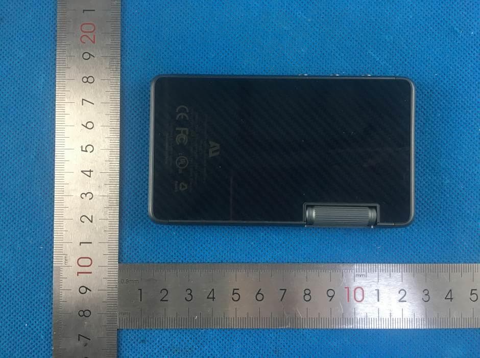
Click to zoom
Application Details
- Equipment Class
- NII - Unlicensed National Information Infrastructure TX
- Date of Grant
- Mar 22, 2020
- Application Purpose
- Original Equipment
- Date of Application
- Mar 22, 2020
- Equipment Note
- High Resolution Streaming Digital Audio Player
- Frequency Range
- 5745.00000000 - 5825.00000000
- Company
- AUSOUNDS INTELLIGENCE, LLC
- Country
- United States
Documents & Files
Document Text
Text extracted from the exhibit documents filed with the FCC. Open a document above to read the original.
Users Manual
AU-D1 QUICK START GUIDE Hi-Res Streaming Digital Audio Player PRODUCT OVERVIEW 3.5mm Headphone Jack (Compatible with 3.5mm Optical Ouptut) 2.5mm Banlance Headphone Jack Top Microphone Power Button (Hold for Power On/Off, Press for Screen Saver) Main Volume Rotator Multi-Points Touch Screen Prev. Song Play/Pause (Hold for Keys Holding) Next Song Hole for Tray-Out Tray for TF / SIM Card (SIM Card is only for special model) USB-C for Charging & Data Bottom Microphone CHARGING Option 1: Connect to a USB adaptor Option 2: Connect to a PC USB port Note: 1.Connect the player to a PC machine or a charging adaptor via the USB port to start charge. 2.Please charge the player before using it if it is not be used for long time. 3. If possible please charge the player at least every month. 4. Please choose “Charge Only” option on the Screen USB Pop-up Menu. DATATRANSFER Connect the player to a PC machine or other possible equipment, and choose the “Data Mode” option on the Screen USB Pop-up Menu. AUSOUNDS MUSIC PLAYER APPLICATION QUICK INTRODUCTION Option All Songs Play List Click to Change Display Information Search Single Song History Playlist Search All Current Play List Songs Favorite Playlist Progress Bar Loop Mode Add to Favorite List You can download detailed product manual from [ www.aus- ounds.com ] FCC Warning This device complies with part 15 of the FCC Rules. Operation is subject to the following two conditions: (1) This device may not cause harmful interference, and (2) this device must accept any interference received, including interference that may cause undesired operation.Any Changes or modifications not expressly approved by the party responsible for compliance could void the user's authority to operate the equipment. This equipment has been tested and found to comply with the limits for a Class B digital device, pursuant to part 15 of the FCC Rules. These limits are designed to provide reasonable protection against harmful interference in a residential installation. This equipment generates uses and can radiate radio frequency energy and, if not installed and used in accordance with the instructions, may cause harmful interference to radio communications. However, there is no guarantee that interference will not occur in a particular installation. If this equipment does cause harmful interference to radio or television reception, which can be determined by turning the equipment off and on, the user is encouraged to try to correct the interference by one or more of the following measures: -Reorient or relocate the receiving antenna. -Increase the separation between the equipment and receiver. -Connect the equipment into an outlet on a circuit different from that to which the receiver is connected. -Consult the dealer or an experienced radio/TV technician for help.The device has been evaluated to meet general RF exposure requirement. The device can be used in portable exposure condition without restriction.
Attestation Statements
AUSOUNDS INTELLIGENCE, LLC ADD: 929 108TH AVE NE STE 1200, BELLEVUE, WA, 98004-4787, UNITED STATES Tel: +86-755 33622851 Fax: +86-755 33622854 Email: [email protected] Declaration Date: 2020/1/9 FEDERAL COMMUNICATIONS COMMISSIONS Authorization and Evaluation Division 7435 Oakland Mills Road Columbia, MD 21046 Dear Sir or Madam, We, AUSOUNDS INTELLIGENCE, LLC, declare that our product High Resolution Streaming Digital Audio Player, Model Number: AU-D1, which chip (model:MT6167) supports the following function: 1. The main chip MT6167 supports 3G / 4G functions and is shielded 2. The main chip MT6167 supports the entire 5G wifi network segment. Only tested B1 and B4, other shields. 3. The main chip MT6167 supports BT V5, only tested BDR + EDR + LE 1M, other shielding but for marketing purpose, these have been shielded by manufacturer though software and the end user can not have the capability to activate these bands. Sincerely, Signature: Name:RUI QIU Tittle:Business Manager FCC ID: 2AT6NAU-D1 ,
Cover Letter(s)
AUSOUNDS INTELLIGENCE, LLC Add: 929 108TH AVE NE STE 1200, BELLEVUE, WA, 98004-4787, UNITED STATES Tel: +86-755 33622851 Email: [email protected] QA-FR-170-B FCC Authorization Date: 2019-12-17 FEDERAL COMMUNICATIONS COMMISSIONS Authorization and Evaluation Division 7435 Oakland Mills Road Columbia, MD 21046 Subject: Agent Authorization To whom it may concern: We, AUSOUNDS INTELLIGENCE, LLC, hereby authorizes Bay Area Compliance Laboratories Corporation to act on its behalf in all matters relating to application for Equipment authorization, including the signing of all documents relating to these matters. All acts carried out by Bay Area Compliance Laboratory Corporation on our behalf shall have the same effect as our own action. We, the undersigned, hereby certify that we are not subject to a denial of federal benefits, that includes FCC benefits, pursuant to Section 5301 of the Anti-Drug Abuse Act of 1988, 21 U.S.C. 862. This authorization is valid until further written notice from the applicant. Sincerely Yours, Signature: Name: RUI QIU Title: Business Manager
Cover Letter(s)
AUSOUNDS INTELLIGENCE, LLC Add: 929 108TH AVE NE STE 1200, BELLEVUE, WA, 98004-4787, UNITED STATES Tel: +86-755 33622851 Email: [email protected] FCC Confidential Authorization Date: 2019-12-17 FEDERAL COMMUNICATIONS COMMISSIONS Authorization and Evaluation Division 7435 Oakland Mills Road Columbia, MD 21046 Subject: Confidentiality Request regarding application for certification of FCC ID: 2AT6NAU-D1 In accordance with Sections 0.457 and 0.459 of the Commission’s Rules, AUSOUNDS INTELLIGENCE, LLC hereby requests long-term confidential treatment of information accompanying this application as outlined below: Block Diagram Schematics Operation Description The above materials contain proprietary and confidential information not customarily released to the public. The public disclosure of these materials provides unjustified benefits to its competitors in the market. Sincerely Yours, Signature: Name: RUI QIU Title: Business Manager U-NII Software Security Description
External Photos
- Page 1 of 3 - Report No.: MTi19111505-4E1-1 Tel:(86-755)88850135 Fax: (86-755) 88850136 Web: http://www.mtitest.com E-mail: [email protected] Address: No.102A & 302A, East Block, Hengfang Industrial Park, Xingye Road, Xixiang, Bao'an District, Shenzhen, Guangdong, China APPENDIX 1: EUT PHOTO Photo 1 (For Model AU-D1) Photo 2 - Page 2 of 3 - Report No.: MTi19111505-4E1-1 Tel:(86-755)88850135 Fax: (86-755) 88850136 Web: http://www.mtitest.com E-mail: [email protected] Address: No.102A & 302A, East Block, Hengfang Industrial Park, Xingye Road, Xixiang, Bao'an District, Shenzhen, Guangdong, China Photo 3 Photo 4 - Page 3 of 3 - Report No.: MTi19111505-4E1-1 Tel:(86-755)88850135 Fax: (86-755) 88850136 Web: http://www.mtitest.com E-mail: [email protected] Address: No.102A & 302A, East Block, Hengfang Industrial Park, Xingye Road, Xixiang, Bao'an District, Shenzhen, Guangdong, China Photo 5 Photo 6 ----END OF REPORT----
ID Label/Location Info
EXHIBIT A - FCC ID LABEL AND LOCATION FCC ID Label FCC ID Label Location Information The label shown shall be permanently affixed at a conspicuous location on the device and be readily visible to the user at the time purchase (Labeling requirements per 2.925)
Internal Photos
- Page 1 of 5 - Report No.: MTi19111505-4E1-1 Tel:(86-755)88850135 Fax: (86-755) 88850136 Web: http://www.mtitest.com E-mail: [email protected] Address: No.102A & 302A, East Block, Hengfang Industrial Park, Xingye Road, Xixiang, Bao'an District, Shenzhen, Guangdong, China APPENDIX 1: EUT PHOTO Photo 1 (For Model AU-D1) Photo 2 FPC Antenna - Page 2 of 5 - Report No.: MTi19111505-4E1-1 Tel:(86-755)88850135 Fax: (86-755) 88850136 Web: http://www.mtitest.com E-mail: [email protected] Address: No.102A & 302A, East Block, Hengfang Industrial Park, Xingye Road, Xixiang, Bao'an District, Shenzhen, Guangdong, China Photo 3 Photo 4 - Page 3 of 5 - Report No.: MTi19111505-4E1-1 Tel:(86-755)88850135 Fax: (86-755) 88850136 Web: http://www.mtitest.com E-mail: [email protected] Address: No.102A & 302A, East Block, Hengfang Industrial Park, Xingye Road, Xixiang, Bao'an District, Shenzhen, Guangdong, China Photo 5 Photo 6 - Page 4 of 5 - Report No.: MTi19111505-4E1-1 Tel:(86-755)88850135 Fax: (86-755) 88850136 Web: http://www.mtitest.com E-mail: [email protected] Address: No.102A & 302A, East Block, Hengfang Industrial Park, Xingye Road, Xixiang, Bao'an District, Shenzhen, Guangdong, China Photo 7 Photo 8 - Page 5 of 5 - Report No.: MTi19111505-4E1-1 Tel:(86-755)88850135 Fax: (86-755) 88850136 Web: http://www.mtitest.com E-mail: [email protected] Address: No.102A & 302A, East Block, Hengfang Industrial Park, Xingye Road, Xixiang, Bao'an District, Shenzhen, Guangdong, China Photo 9 Photo 10 ----END OF REPORT----
RF Exposure Info
RF EXPOSURE REPORT FCC ID: 2AT6NAU-D1 Date of issue: Dec. 16, 2019 Report Number: MTi19111505-4E5 Sample Description: High Resolution Streaming Digital Audio Player Mo d e l( s ) : AU-D1 Applicant: AUSOUNDS INTELLIGENCE, LLC Address: 929 108TH AVE NE STE 1200, BELLEVUE, WA, 98004- 4787, UNITED STATES Date of Test: Nov. 19, 2019 to Dec. 10, 2019 Shenzhen Microtest Co., Ltd. http://www.mtitest.com - Page 2 of 6- Report No.: MTi19111505-4E5 TEST RESULT CERTIFICATION Applicant’s name: AUSOUNDS INTELLIGENCE, LLC Address: 929 108TH AVE NE STE 1200, BELLEVUE, WA, 98004-4787, UNITED STATES Manufacture's name: Shenzhen Ausounds Intelligence Co., Ltd. Address: 606B, 6th Floor, Xuyuan Building, No. 5003 Longgang Avenue, Longgang District, Shenzhen Product name: High Resolution Streaming Digital Audio Player Model and/or type reference: AU-D1 Serial Model: N/A RF Exposure Procedures: KDB 447498 D01 v06 This device described above has been tested by Shenzhen Microtest Co., Ltd and the test results show that the equipment under test (EUT) is in compliance with the FCC requirements. And it is applicable only to the tested sample identified in the report. Tested by: Demi Mu Dec. 10, 2019 Reviewed by: Blue Zheng Dec. 16, 2019 Approved by: Smith Chen Dec. 16, 2019 - Page 3 of 6- Report No.: MTi19111505-4E5 1. Standalone SAR test exclusion considerations Unless specifically required by the published RF exposure KDB procedures, standalone 1-g head or body and 10-g extremity SAR evaluation for general population exposure conditions, by measurement or numerical simulation, is not required when the corresponding SAR Test Exclusion Threshold condition(s), listed below, is (are) satisfied. These test exclusion conditions are based on source-based time-averaged maximum conducted output power of the RF channel requiring evaluation, adjusted for tune-up tolerance, and the minimum test separation distance required for the exposure conditions. The minimum test separation distance defined in 4.1 f) is determined by the smallest distance from the antenna and radiating structures or outer surface of the device, according to the host form factor, exposure conditions and platform requirements, to any part of the body or extremity of a user or bystander. To qualify for SAR test exclusion, the test separation distances applied must be fully explained and justified, typically in the SAR measurement or SAR analysis report, by the operating configurations and exposure conditions of the transmitter and applicable host platform requirements, according to the required published RF exposure KDB procedures. When no other RF exposure testing or reporting are required, a statement of justification and compliance must be included in the equipment approval, in lieu of the SAR report, to qualify for SAR test exclusion. When required, the device specific conditions described in the other published RF exposure KDB procedures must be satisfied before applying these SAR test exclusion provisions. a) For 100 MHz to 6 GHz and test separation distances ≤ 50 mm, the 1-g and 10-g SAR test exclusion thresholds are determined by the following: [(max. power of channel, including tune-up tolerance, mW) / (min. test separation distance, mm)] · [√f(GHz)] ≤ 3.0 for 1-g SAR, and ≤ 7.5 for 10-g extremity SAR, where f (GHz) is the RF channel transmit frequency in GHz Power and distance are rounded to the nearest mW and mm before calculation The result is rounded to one decimal place for comparison The values 3.0 and 7.5 are referred to as numeric thresholds in step b) below The test exclusions are applicable only when the minimum test separation distance is ≤ 50 mm, and for transmission frequencies between 100 MHz and 6 GHz. When the minimum test separation distance is < 5 mm, a distance of 5 mm according to 4.1 f) is applied to determine SAR test exclusion. b) For 100 MHz to 6 GHz and test separation distances > 50 mm, the 1-g and 10-g SAR test exclusion thresholds are determined by the following (also illustrated in Appendix B): 1) {[Power allowed at numeric threshold for 50 mm in step a)] + [(test separation distance – 50 mm)·(f(MHz)/150)]} mW, for 100 MHz to 1500 MHz 2) {[Power allowed at numeric threshold for 50 mm in step a)] + [(test separation distance – 50 mm)·10]} mW, for > 1500 MHz and ≤ 6 GHz c) For frequencies below 100 MHz, the following may be considered for SAR test exclusion (also illustrated in Appendix C): 1) For test separation distances > 50 mm and < 200 mm, the power threshold at the corresponding test separation distance at 100 MHz in step b) is multiplied by [1 + log(100/f(MHz))] 2) For test separation distances ≤ 50 mm, the power threshold determined by the equation in c) 1) for 50 mm and 100 MHz is multiplied by ½ 3) SAR measurement procedures are not established below 100 MHz. - Page 4 of 6- Report No.: MTi19111505-4E5 When SAR test exclusion cannot be applied, a KDB inquiry is required to determine SAR evaluation requirements for any SAR test results below 100 MHz to be acceptable. 2. SAR Test Exclusion Thresholds We use 5mm as separation distance to calculate. Bluetooth DSS: Transmit Frequency (GHz) Mode Measured Power (dBm) Tune- up power (dBm) Max tune-up Result Exclusion thresholds power(dBm) calculation 2.402 GFSK 7.694 7±1 8 1.9558 3 2.441 6.720 7±1 8 1.9716 3 2.480 6.984 7±1 8 1.9873 3 2.402 π/4- DQPSK 7.400 7±1 8 1.9558 3 2.441 6.923 7±1 8 1.9716 3 2.480 6.470 7±1 8 1.9873 3 2.402 8DPSK 7.470 7±1 8 1.9558 3 2.441 6.850 7±1 8 1.9716 3 2.480 6.330 7±1 8 1.9873 3 Bluetooth DTS: Transmit Frequency (GHz) Mode Measured Power (dBm) Tune-up power (dBm) Max tune-up Result 1g SAR power(dBm) calculation 2.402 GFSK -6.01 -6±1 -5 0.0980 3 2.440 -6.66 -6±1 -5 0.0988 3 2.480 -6.68 -6±1 -5 0.0996 3 2.4GWiFi Transmit Frequency (GHz) Mode Measured Power (dBm) Tune-up power (dBm) Max tune-up Result Exclusion thresholds power(dBm) calculation 2.412 802.11b 9.47 8.5±1 9.5 2.7683 3 2.437 9.48 8.5±1 9.5 2.7826 3 2.462 9.45 8.5±1 9.5 2…
Text truncated - open the document above for the full version.
Test Report
This test report is valid for the tested samples only. It cannot be reproduced except in full without prior written consent of Shenzhen Microtest Co., Ltd. Tel:(86-755)88850135 Fax: (86-755) 88850136 Web: http://www.mtitest.com E-mail: [email protected] Address: No.102A & 302A, East Block, Hengfang Industrial Park, Xingye Road, Xixiang, Bao'an District, Shenzhen, Guangdong, China Test Report FCC ID: 2AT6NAU-D1 Date of issue: Feb. 25, 2020 Report number: MTi19111505-4E4 Sample description: High Resolution Streaming Digital Audio Player Model(s): AU-D1 Applicant: AUSOUNDS INTELLIGENCE, LLC Address: 929 108TH AVE NE STE 1200, BELLEVUE, WA, 98004-4787, UNITED STATES Date of test: Nov. 19, 2019 to Feb. 25, 2020 Shenzhen Microtest Co., Ltd. http://www.mtitest.com - Page 2 of 62 - Report No.: MTi19111505-4E4 Tel:(86-755)88850135 Fax: (86-755) 88850136 Web: http://www.mtitest.com E-mail: [email protected] Address: No.102A & 302A, East Block, Hengfang Industrial Park, Xingye Road, Xixiang, Bao'an District, Shenzhen, Guangdong, China Table of Contents 1 GENERAL INFORMATION .......................................................................................................................................... 4 1.1 DESCRIPTION OF EUT ................................................................................................................................................... 4 1.2 OPERATION CHANNEL LIST .............................................................................................................................................. 5 1.3 TEST CHANNEL LIST ....................................................................................................................................................... 5 1.4 ANCILLARY EQUIPMENT LIST ........................................................................................................................................... 6 1.5 DESCRIPTION OF SUPPORT UNITS .................................................................................................................................... 6 2 SUMMARY OF THE TEST RESULTS ............................................................................................................................. 7 3 TEST FACILITIES AND ACCREDITATIONS ..................................................................................................................... 8 3.1 TEST LABORATORY ........................................................................................................................................................ 8 3.2 ENVIRONMENTAL CONDITIONS ........................................................................................................................................ 8 3.3 MEASUREMENT UNCERTAINTY ........................................................................................................................................ 9 3.4 TEST SOFTWARE ........................................................................................................................................................... 9 4 EQUIPMENT LIST .................................................................................................................................................... 10 5 TEST RESULTS ......................................................................................................................................................... 12 5.1 ANTENNA REQUIREMENT ............................................................................................................................................. 12 5.1.1 Standard requirement ....................................................................................................................................... 12 5.1.2 EUT Antenna ..................................................................................................................................................... 12 5.2 RF OUTPUT POWER .................................................................................................................................................... 13 5.2.1 Limit .................................................................................................................................................................. 13 5.2.2 Test procedure ................................................................................................................................................... 13 5.2.3 Test setup .......................................................................................................................................................... 13 5.2.4 Test results......................................................................................................................................................... 14 5.3 POWER LINE CONDUCTED EMISSION ............................................................................................................................... 16 5.3.1 Limits ................................................................................................................................................................. 16 5.3.2 Test setup .......................................................................................................................................................... 16 5.3.3 Test procedure ................................................................................................................................................... 17 5.3.4 Test results......................................................................................................................................................... 18 5.4 26DB EMISSION BANDWIDTH AND OCCUPIED BANDWIDTH ................................................................................................ 22 5.4.1 Limit .................................................................................................................................................................. 22 5.4.2 Test pr…
Text truncated - open the document above for the full version.
Test Setup Photos
Model: AU-D1 Radiated emission Conducted emission
Contact Information
Applicant
RUI QIU(Business Manager)
Test Firm
Shenzhen Microtest Co., Ltd.Selby Liao
[email protected]0755-88850135-1193
Technical Specifications
| # | Rule Parts | Frequency Range | Power Output |
|---|---|---|---|
| 2 | 15E | 5.75 GHz - 5.83 GHz | 4.00 mW |
Other Applications from AUSOUNDS INTELLIGENCE, LLC
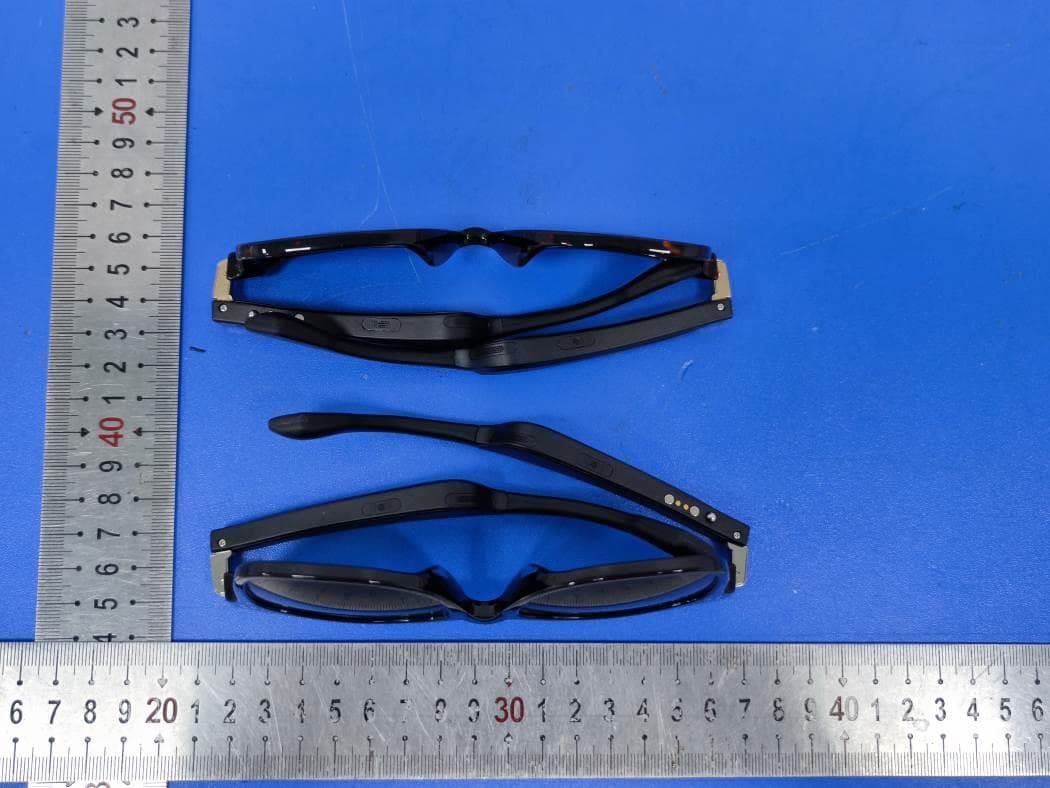
2AT6N-AU-LENS
Mar 20, 2021Bluetooth Glasses
Equipment Class
DSS - Part 15 Spread Spectrum Transmitter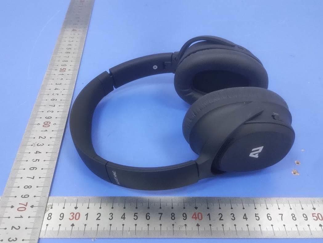
2AT6N-50H
Jan 28, 2021Bluetooth Headset
Equipment Class
DTS - Digital Transmission System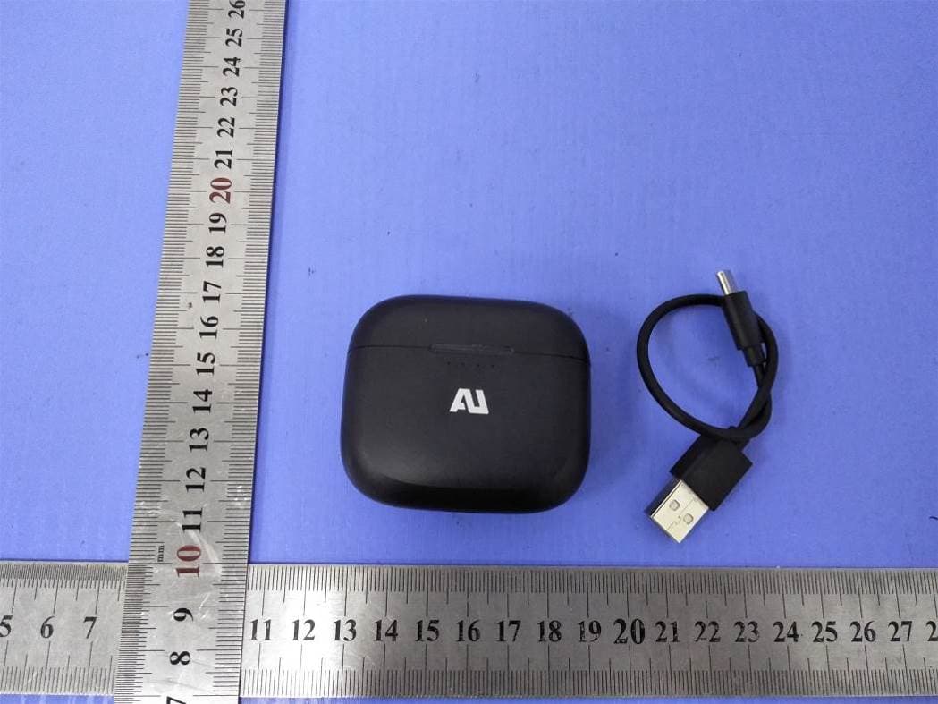
2AT6N-T20B
Nov 02, 2020TWS Bluetooth headset
Equipment Class
DSS - Part 15 Spread Spectrum Transmitter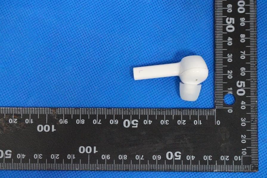
2AT6N-B20
Jun 22, 2020AU-stream
Equipment Class
DSS - Part 15 Spread Spectrum Transmitter
2AT6N-20HBR
May 19, 2020AU-STREAM Hybrid
Equipment Class
DTS - Digital Transmission System