2AT8F-AN-H50Ultrasonic Humidifier
Guangdong Mixwell Technology Co., Ltd.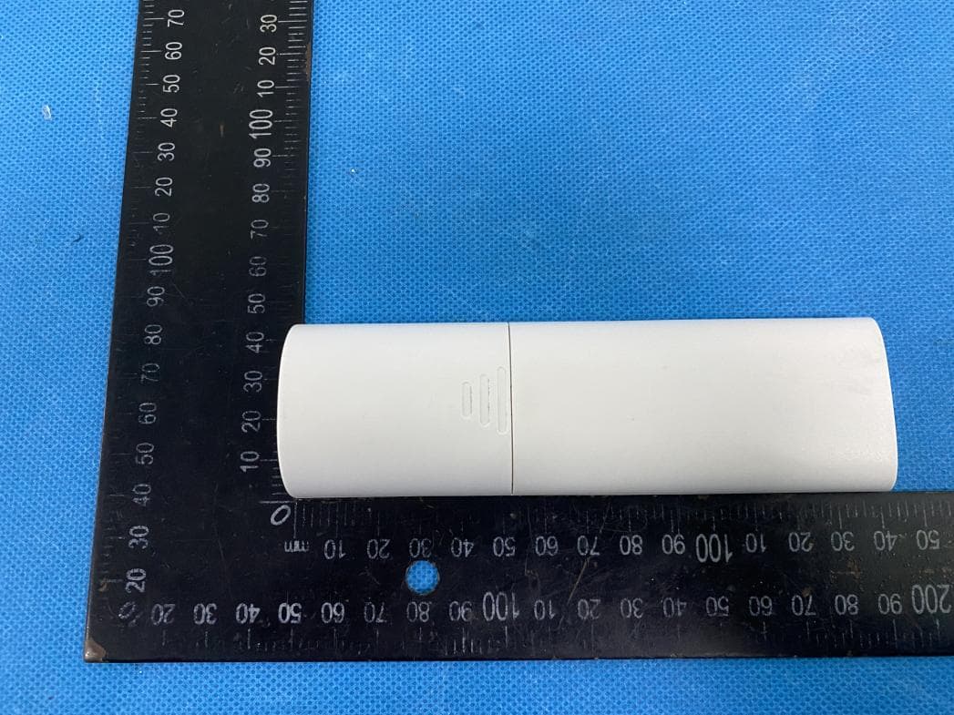
Click to zoom
Application Details
- Equipment Class
- DTS - Digital Transmission System
- Date of Grant
- Nov 22, 2022
- Application Purpose
- Original Equipment
- Date of Application
- Nov 22, 2022
- Equipment Note
- Ultrasonic Humidifier
- Frequency Range
- 2402.00000000 - 2480.00000000
- Country
- China
Documents & Files
Document Text
Text extracted from the exhibit documents filed with the FCC. Open a document above to read the original.
Users Manual
AN-H50 Ultrasonic Humidifier User Manual [email protected] Product overview EN-01 Nozzle Water Tank Remote Control Cable Socket Ultrasonic Chip Mist Pipe Main Body Button Handle Cover Aroma Tray Float EN-02 NOTEPlease take notice of below instructions and the separately included warning sheet before using the product. FCC STATEMENT 1. This device complies with Part 15 of the FCC Rules. Operation is subject to the following two conditions: (1) This device may not cause harmful interference, and (2) This device must accept any interference received, including interference that may cause undesired operation. 2. Changes or modifications not expressly approved by the party responsible for compliance could void the user’s authority to operate the equipment. This equipment has been tested and found to comply with the limits for a Class B digital device, pursuant to part 15 of the FCC Rules. These limits are designed to provide reasonable protection against harmful interference in a residential installation. This equipment generates, uses and can radiate radio frequency energy and, if not installed and used in accordance with the instructions, may cause harmful interference to radio communications. However, there is no guarantee that interference will not occur in a particular installation. If this equipment does cause harmful interference to radio or television reception, which can be determined by turning the equipment off and on, the user is encouraged to try to correct the interference by one or more of the following measures: — Reorient or relocate the receiving antenna. — Increase the separation between the equipment and receiver. — Connect the equipment into an outlet on a circuit different from that to which the receiver is connected. — Consult the dealer or an experienced radio/ TV technician for help. Installation ·Please do not set up the device in a place where humidity directly hits curtains, furniture, indoor plants or doors. It can cause stains and deformation. ·Please place the device on a horizontal and stable surface, otherwise it might be a risk of water spilling. ·Please do not set up the device in a place where only children are present such as children’s room. It can lead to injury or breakdown if the device is knocked over or climbed on. ·Please do not place the device anywhere where it may fall from above. It can lead to ignition or a breakdown. EN-03 ·Please do not set up the device near devices that are not compatible with water such as PCs or smartphones. It can cause ignition or a breakdown. ·Please do not use up the device in any surrounding that could lead to the water in the water tray or in the device to freeze. However, if the water in the water tray or the device is frozen please do not operate the device until the ice has thawed. It can cause ignition or a breakdown. Placement Please place the device away from walls, window and furniture. Back: at least 30cm Side: at least 30cm Side: at least 30cm Front: at least 30cm Top: at least 100cm ·Even when it is placed at a sufficient distance from walls or furniture, if it is used in the same place for a long period of time, it can become dirty with scale. We recommend regular cleaning. Please refer to maintenance instructions. ·Please avoid placing the device under direct sunlight. ·If there is interference with TV, radio or other electrical devices, please move the device. ·When moving the device, please hold the base of the device carefully. · A comfortable humidity level is between 40-60%. If you notice condensa- tion on the walls or windows you should turn off your humidifier as the humidity level is too high. EN-04 ·Remove the cover, then fill the water tank. ·Please do not fill water exceeding the max water line marked in the main body. ·Please try to fill water slowly. And do not pour water into the air outlet and mist pipe. This will cause the mist to stop. If there is water in the mist pipe, remove the mist pipe and drain and try again. Remove the water tank from the base. Fill the water tank under the tap directly. Do not pour water into the air outlet and mist pipe. Pour the water slowly from the top. Filling the water tank 1 2 3 12 3 Operation Plug the power cable into the power socket of the device, and insert the AC plug firmly into the outlet. EN-05 Control panel and function Power button When connecting the power, the power indicator light will turn red, and the device will be standby. Touch the button, the device will be turned on/off. Power Timer indicator light Power indicator light Mist volume indicator light Timer Mist volume Timer button (2/4/6hours) When you touch the timer button for the 1st time, the timer will be set 2 hours. When you touch the button for the 2nd time, it will be set 4 hours. When you touch the button for the 3rd time, it will be set 6 hours. Each time you touch the setting button, the display of humidifier indicator light is as below. Indicator light Remaining time4 to 6 hours2 to 4 hoursless than 2 hours No timer2 hours4 hours6 hours Remote control Mist volume setting button The mist volume can be set in three-stage: about 120(low) /170(medium) / 220(high) ml/h. Each time you touch the setting button, the display of humidifier indicator light is as below. WeakMediumStrong EN-06 The device also synchronizes with the remote control when operating the speed, timer and switching the device on and off. Remote control for 2.4 g induction, 360 degrees operation and remote operation (more than 10 meters). Auto Display Temp. Switch Mist Volume Timer FrontBack Power Battery Cover EN-07 Display Power button When connecting the power, the power indicator light will turn red, and the device will be standby. Touch the button, the device will be turned on/off. 15s without operation, remote Control will automatically light off, and you can press the button to light up the screen. Displayed on the remote control are synchronized with the contents displayed on the device. Timer butto…
Text truncated - open the document above for the full version.
Attestation Statements
Guangdong Mixwell Technology Co., Ltd. 1-4#F,A building,No.7,Yu Hua Street,138 Industrial Area,TangXia,DongGuan,China Date: 11/18/2022 FCC ID: 2AT8F-AN-H50 Model Number: AN-H50 To: Federal Communication Commission Authorization and Evaluation Division 7435 Oakland Mills Road Columbia, MD 21048 To Whom It May Concern, We, Guangdong Mixwell Technology Co., Ltd. declare that this EUT (FCC ID: 2AT8F-AN-H50) will conduct FCC compliance testing, the sDOC part recognized test lab(ShenzhenNTEK Testing Technology Co., Ltd.). 1/F, Building E, Fenda Science Park, Sanwei Community,Xixiang Street Bao’an District, Shenzhen 518126 P.R. China Please contact me if you have any question. Sincerely, (Signed) Name:Napoleon Zeng Phone: +86-769-82994993 Fax:+86-769-23301600 Email: [email protected]
Cover Letter(s)
Rev 11/20/07 (Guangdong Mixwell Technology Co., Ltd.) Federal Communications Commission Authorization and Evaluation Division Confidentiality Request regarding application for certification of FCC ID: 2AT8F-AN-H50 Pursuant to Sections 0.457 and 0.459 of the Commission’s Rules, we hereby request confidential treatment of information accompanying this application as outlined below: Exhibit Type File Name (ie- Block Diagram, Schematics, Operational Description, Parts List, Tune Up Info) (ie- “1100_schematics.pdf”) Schematic Diagram Block Diagram Operational Description Schematic Diagram Block Diagram Operational Description The above materials contain trade secrets and proprietary information not customarily released to the public. The public disclosure of these materials may be harmful to the applicant and provide unjustified benefits to its competitors. The applicant understands that pursuant to Section 0.457 of the Rules, disclosure of this application and all accompanying documentation will not be made before the date of the Grant for this application. Pursuant to DA04-1705 June 15, 2004 of the Commission’s public notice, we also request temporary confidential treatment of information accompanying this application as outlined below: requests short-term Confidentiality of following sections of this application for a period of 180 days after grant is issued. Exhibit Type File Name (ie- External Photos, Internal Photos, Test Setup Photos, Manual) (ie- “1100_external photos.pdf”) External Photos Test Setup Photos Internal Photos User Manual External Photos Test Setup Photos Internal Photos User Manual Sincerely, (signature) (printed name): Napoleon Zeng Date: 11/18/2022
Cover Letter(s)
H:\电磁兼容部\RF项目组\RF项目\2022\9月\S22092902501001东莞北测 Ultrasonic Humidifier(2.4G) AN-H50 FCC ID RF\6. Submission\letter\FCC ID\FCC POA Letter.docx (Guangdong Mixwell Technology Co., Ltd.) Federal Communications Commission Authorization and Evaluation Division 1435 Oakland Mills Road Columbia, MD 21046 Date: 11/18/2022 SUBJECT: FCC Application for FCC ID: 2AT8F-AN-H50 To Whom It May Concern: We, the undersigned, hereby authorize Alex Li at Shenzhen NTEK Testing Technology Co., Ltd. on our behalf, to apply to the Federal Communications Commission on our equipment. Any and all acts carried out by Shenzhen NTEK Testing Technology Co., Ltd. on our behalf shall have the same effect as acts of our own. This is to advise that we are in full compliance with the Anti- Drug Abuse Act. We, the applicant, are not subject to a denial of federal benefits pursuant to Section 5301 of the Anti-Drug Act of 1988, 21 USC853a, and no party to the application is subject to a denial of federal benefits pursuant to that section. Regards, (signature) (printed name): Napoleon Zeng
External Photos
ATTACHMENT PHOTOGRAPHS OF EUT Photo 1 Photo 2 Photo 3 Photo 4 Photo 5 Photo 6 Photo 7 Photo 8
ID Label/Location Info
35.5 mm 44.5 mm Ultrasonic Humidifier Model: AN-H50 Voltage: 100-240V~, 50/60Hz Power: 22W FCC ID: 2AT8F-AN-H50 Manufacturer: Guangdong Mixwell Technology Co., Ltd. 1-4#F, A building, NO.7 Yuhua street, 138 Industrial Area,Tangxia, Dongguan, Guangdong, China MADE IN CHINA FrontBack Battery Cover label location
Internal Photos
Photo 9 Photo 10 Photo 11 Photo 12 Ant
RF Exposure Info
FCC ID: 2AT8F-AN-H50 Portable device According to §15.247(e)(i) and §1.1307(b)(1), systems operating under the provisions of this section shall be operated in a manner that ensures that the public is not exposed to radio frequency energy level in excess of the Commission’s guidelines. According to KDB447498 D01 General RF Exposure Guidance V06 The 1-g SAR and 10-g SAR test exclusion thresholds for 100 MHz to 6 GHz at test separation distances ≤ 50 mm are determined by: [(max. power of channel, including tune-up tolerance, mW)/(min. test separation distance, mm)]·[√f(GHZ)] ≤ 3.0 for 1-g SAR and ≤ 7.5 for 10-g extremity SAR, where: • f(GHZ) is the RF channel transmit frequency in GHz • Power and distance are rounded to the nearest mW and mm before calculation • The result is rounded to one decimal place for comparison When the minimum test separation distance is < 5 mm, a distance of 5 mm is applied to determine SAR test exclusion. Antenna Type: PCB Antenna Antenna Gain: 2dBi Modulation Channel Freq. (GHz) Conduct ed power (dBm) Conducte d power (mW) Tune-up power (dBm) Max tune-up power (dBm) Max tune-up power (mW) Distance (mm) Result calculatio n 1g SAR Exclusion threshold SAR test exclusion 2.4020.891.2271±12.01.585<50.491273.00YES 2.4400.6641.1651±12.01.585<50.495143.00YES 2.4801.9931.5821±12.01.585<50.499183.00YES GFSK Conclusion: For the max result : 0.49918≤ 3.0 for 1-g SAR, No SAR is required. Signature: Date: 2022-10-20 NAME AND TITLE (Please print or type): Alex Li /Manager COMPANY (Please print or type): Shenzhen NTEK Testing Technology Co., Ltd./ 1/F, Building E, Fenda Science Park, Sanwei Community, Xixiang Street Bao’an District, Shenzhen 518126 P.R. China
Test Report
Shenzhen lingchengxin Electronics Co., Ltd Wireless module Ling-TR2 specification 515, block D, Huayuan science and Technology Innovation Park, Baoyuan Road, Xixiangstreet, Bao'an District, Shenzhen, Guangdong 1、Introduction Ling-TR2adopts 2.4G SOC technology, which is development-free; module communication is about 100 m, serial transparent transmission and high integration of the serial communication can complete the development of remote control products and data transmission products. 2 、Characteristics ● semi-duplex communication ● 2.4GHz ISM band ● power supply voltage2.8-3.6V ● reception sensitivity-95dBm ● emission operating current 40mA ● receives an operating current 27mA ● sleep current 9.5uA ● standard TTL level UART serial port ● frequency can be set, with multiple modules without interference ● sending and receiving switching is automatically completed, ● communication rate is 0.6kbps-38.4kbps 3、Pin definition pin Lead the foot name Feet function description 1 VCC + 2.8~3.6V, Typical 3.3V 2 RXD Module data input (TTL level) Serial port communication data reception 3 TXD Module data output (TTL level) Serial port communication data transmission 4 SET Set position Configuration parameters enable (low level is configuration mode, suspended or high level is communication mode) 5 CS dormancy Pin working at low level, suspended or dormant at high level 6 GND - - 7 ANT External antenna interface When connecting with the external antenna, the resistance at the PCB antenna connection should be removed. 4、Product size
Test Report
Report No.: S22092902501001 Version.1.3 Page 1 of 45 RADIO TEST REPORT FCC ID: 2AT8F-AN-H50 Product: Ultrasonic Humidifier Trade Mark: Ausanat Model No.: AN-H50 Family Model: N/A Report No.: S22092902501001 Issue Date: Oct. 19, 2022 Prepared for GuangDong Mixwell Technology Co.,Ltd. 1-4#F,A building,No.7,Yu Hua Street,138 Industrial Area,TangXia,DongGuan,China Prepared by Shenzhen NTEK Testing Technology Co., Ltd. 1/F, Building E, Fenda Science Park, Sanwei Community, Xixiang Street Bao’an District, Shenzhen 518126 P.R. China Tel. 400-800-6106, 0755-2320 0050, 0755-2320 0090 Website: http://www.ntek.org.cn Report No.: S22092902501001 Version.1.3 Page 2 of 45 TABLE OF CONTENTS 1 TEST RESULT CERTIFICATION ...................................................................................................................... 3 2 SUMMARY OF TEST RESULTS ......................................................................................................................... 4 3 FACILITIES AND ACCREDITATIONS ............................................................................................................. 5 3.1 FACILITIES..................................................................................................................................................... 5 3.2 LABORATORY ACCREDITATIONS AND LISTINGS ................................................................................. 5 3.3 MEASUREMENT UNCERTAINTY ............................................................................................................... 5 4 GENERAL DESCRIPTION OF EUT .................................................................................................................. 6 5 DESCRIPTION OF TEST MODES ..................................................................................................................... 8 6 SETUP OF EQUIPMENT UNDER TEST ........................................................................................................... 9 6.1 BLOCK DIAGRAM CONFIGURATION OF TEST SYSTEM ....................................................................... 9 6.2 SUPPORT EQUIPMENT............................................................................................................................... 10 6.3 EQUIPMENTS LIST FOR ALL TEST ITEMS .............................................................................................. 11 7 TEST REQUIREMENTS .................................................................................................................................... 13 7.1 CONDUCTED EMISSIONS TEST ............................................................................................................... 13 7.2 RADIATED SPURIOUS EMISSION ............................................................................................................ 15 7.3 6DB BANDWIDTH ....................................................................................................................................... 24 7.4 DUTY CYCLE ............................................................................................................................................... 25 7.5 PEAK OUTPUT POWER .............................................................................................................................. 27 7.6 POWER SPECTRAL DENSITY ................................................................................................................... 28 7.7 CONDUCTED BAND EDGE MEASUREMENT......................................................................................... 30 7.8 SPURIOUS RF CONDUCTED EMISSIONS................................................................................................ 31 7.9 ANTENNA APPLICATION .......................................................................................................................... 32 8 TEST RESULTS ................................................................................................................................................... 33 8.1 MAXIMUM CONDUCTED OUTPUT POWER ....................................................................................................... 33 8.2 OCCUPIED CHANNEL BANDWIDTH .................................................................................................................. 35 8.3 MAXIMUM POWER SPECTRAL DENSITY LEVEL ............................................................................................... 39 8.4 BAND EDGE .................................................................................................................................................... 41 8.5 CONDUCTED RF SPURIOUS EMISSION ............................................................................................................. 43 Report No.: S22092902501001 Version.1.3 Page 3 of 45 1 TEST RESULT CERTIFICATION Applicant’s name ......................... : GuangDong Mixwell Technology Co.,Ltd Address ....................................... : 1-4#F,A building,No.7,Yu Hua Street,138 Industrial Area,TangXia,DongGuan,China Manufacturer's Name .................. : GuangDong Mixwell Technology Co.,Ltd Address ....................................... : 1-4#F,A building,No.7,Yu Hua Street,138 Industrial Area,TangXia,DongGuan,China Product description Product name .............................. : Ultrasonic Humidifier Model and/or type reference ...... : AN-H50 Family Model ............................... : N/A Test Sample Number....................: S220929025001 Measurement Procedure Used: APPLICABLE STANDARDS APPLICABLE STANDARD/ TEST PROCEDURE TEST RESULT FCC 47 CFR Part 2, Subpart J FCC 47 CFR Part 15, Subpart C ANSI C63.10-2013 KDB 558074 D01 15.247 Meas Guidance v05r02 Complied This device described above has been tested by Shenzhen NTEK Testing Technology Co., Ltd., and the test results show that the equipment under test (EUT) is in compliance with the FCC requirements. And it is applicable only to the tested sample id…
Text truncated - open the document above for the full version.
Test Setup Photos
Radiated Measurement Photos
Contact Information
Applicant
Napoleon Zeng(Manufacturing Manager)
Test Firm
Shenzhen NTEK Testing Technology Co., Ltd.Alex Li
[email protected]+86-755-6115-9384
Technical Specifications
| # | Rule Parts | Frequency Range | Power Output |
|---|---|---|---|
| 1 | 15C | 2.40 GHz - 2.48 GHz | 1.58 mW |