2AT8P-WS-SR-US-TSmart Switch
Wenzhou Morning Electronics Co.,LTD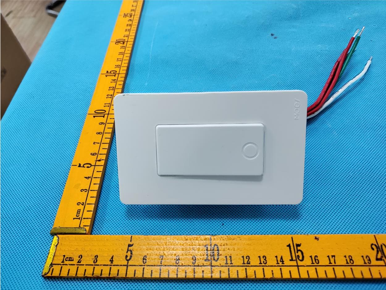
Click to zoom
Application Details
- Equipment Class
- DTS - Digital Transmission System
- Date of Grant
- Dec 21, 2022
- Application Purpose
- Original Equipment
- Date of Application
- Dec 21, 2022
- Equipment Note
- Smart Switch
- Frequency Range
- 2412.00000000 - 2462.00000000
- Country
- China
Documents & Files
Document Text
Text extracted from the exhibit documents filed with the FCC. Open a document above to read the original.
Users Manual
200MM 520MM 65MM 正面 反面 1 2 3 正面 正面 正面 200X455MM 四色印刷 80g哑光纸 风琴折 Instruction Manual Smart Switch Wi-Fi Single Pole / 3 Way Scan the QR code Please connect the device according to the configuration process. 1. Method one: 2. Method two: Scan the QR code to configure the network guide. HOME, SMART MOES HOME English ①② L1 Line/Load L2 Neutral L1 Line/Load L2 Neutral L1 Line/Load L2 Neutral L1 Line/Load L2 Neutral L1Line/LoadL2Neutral BH19 Thank you for your support and purchase at we Moes,we are always here for your complete satisfaction,just feel free to share your great shopping experience with us. If you have any other need,please do not hesitate to contact us first,we will try to meet your demand. Locate your circuit breaker panel and turn off the power to each switch you are replacing. Remove the switch and pull it away from the wall. 2 1 STEP 2 STEP 1 Circuit breaker panel Turn Off Power Input Power: Control Principle : Wireless Protocol: Max Current: Standby Power: Button Life: 100~245V AC 50/60Hz Model:WS-SR-US-T Relay WiFi 802.11 b/g/n 2.4GHz 10A ≤0.5W 500K times 106*45*35 mmDimension: STEP 5 STEP 7 STEP 10 ON/OFF LED Indicator Cover Panel Switch Status Light StatusLight Color White OFF ON Power OFF Power ON Blink Quickly (0.5s ) Blink Slowly (1s ) Ready for AP (Access Point) configuration mode Ready for default configuration mode Tools you’ll need Flat-head screwdriver Phillips-head screwdriverPliers Electricity can cause personal injury and property damage if handled improperly.If you are not sure about any part of these instructions, please seek professional assistance from a qualified electrician. Ensure all wark meets applicable local and national codes. WARNING: RISK OF ELECTRIC SHOCK Voltage tester Approximately 30 minutes to install and setup the switch 30min 3 4 STEP 3 STEP 4 Verify Power is Off Pull Out Old Switch You may need to turn off more than one circuit breaker. We recommend you to remove the faceplate from the old switch and use an electrical tester to test all wires connected to the switch to ensure there is no voltage in the circuit. STEP 6 STEP 9 Mount the switch 1 2 STEP 11 STEP 12 Turn on the power 3.Open Smart Life/Tuya App and Click“+”,then the prompt page will automatically show on the screen.Click “Go to add”. Pair and clear up the WiFi code with Bluetooth and WiFi connected meantime.(New Updated) 2.Make sure your phone is connected to Wi-Fi and Bluetooth. 1.Press and hold switch button for 6s until the white indicator flashes to reset the switch and get into quick configure mode. Complete the wiring of the switch module before pairing Complete the device's networking configuration according to the prompts in the App. STEP 1 If you have already configured Google Home, you can skip this step. The following instructions are based on the iOS client. STEP 2 Control the device via voice commands, now you can control your smart device with Google Home. You can control your device (such as your bedroom light) with the following commands: STEP 4 Key step —— Link Skill STEP 3 Tap on "Skills" in the Alexa App menu. Make sure you Google Home device is powered on and connected to a Wi-Fi network. Open the Google Home App on your phone. After successful login, tap on the menu in the upper left corner and select “SET UP” to set up Google Home. It will notify you with a sound to ensure that you are connected to the correct device. After you hear the sound, tap “YES” to proceed to the next step. You can choose to differentiate the room where Google Home is located from other Google devices. Then, select the Wi-Fi network and language, wait for the system to complete the configuration, and tap “next”. According to the page prompts, choose whether to agree to the corresponding operation. When the page displays “Google Home is ready,” select “continue” to the next step. Next is the voice control guide tutorial. Once you are done listening, tap "FINISH SET UP". At this point, Google Home setup is complete. Ok Google, turn on/off bedroom light. Ok Google, set bedroom light to 50 percent. Ok Google, brighten bedroom light. Ok Google, set bedroom light to red. 4.Select the device you want to add and click “+” 5.Enter Wi-Fi Password and click “Next”,waiting for completing the connection. Note: The switch only supports 2.4G network.If you have connected 5G network,please disconnect 5G network firstly and connect 2.4G network. STEP 3 Key step —— Link Skill Complete the device's networking configuration according to the prompts in the App. STEP 1 STEP 2 Control the device via voice commands, now you can control your smart device with Echo. You can control your device (such as your bedroom light) with the following commands STEP 4 Make sure you Amazon Echo device is powered on and connected to a Wi-Fi network. Enter the App account and password, then tap “Link Now” to link your App account to enable the Skill. Now you can start your smart home journey. Open the Alexa App on your phone. After successful login, tap on the menu in the upper left corner of the Home page, select "Settings" and tap "Set Up A New Device" to set up the Amazon Echo. Choose your Amazon Echo device type and language for connecting. Press and hold the small dot on the d evice until the light turns yellow. Then tap “Continue” to connect to the hotspot. After connecting to the Amazon Echo hotspot, return to the page. At this point, the connection is successful. Tap “Continue” to proceed to the next step. Choose a Wi-Fi network to connect to. Amazon Echo will take a few minutes to try to connect to the network. After the network connection is successful, tap “Continue”. An introduction video will appear. After the video ends, tap “Continue” to jump to the Alexa Home page. You have now completed the Amazon Echo's configuration process. Then search for "App Name". Tap "Enable" to enable the Skill. On the main page of the Google Home App, tap the sidebar menu in the top left corner and select “Home Control”. Alexa, tu…
Text truncated - open the document above for the full version.
Cover Letter(s)
WenzhouMorningElectronicsCo.,Ltd. AgentAuthorization Company:WenzhouMorningElectronicsCo.,Ltd. WeauthorizeMiCOMLabsInc.,575BoulderCourt,Pleasanton,California94566,USA, toactonourbehalfonallmattersconcerningthecertificationofabovenamed equipment. WedeclarethatMiCOMLabsInc.isallowedtoforwardallinformationrelatedtothe approvalandcertificationofequipmenttotheregulatoryagenciesasrequiredandto discussanyissuesconcerningtheapprovalapplication.Anyandallactscarriedoutby MiCOMLabsonourbehalfshallhavethesameeffectasactsofourown Address: Product Name:Smart Switch Model Number(s):WS-SR-US-T、WS-SR-US、WS-SR-US-ABI、WS-SR-US-L、ZS- SR-US 、 ZS-SR-US-T 、 ZS-SR-US-L 、 BS-SR-US 、 BS-SR-US-T 、 BS-SR-US-L 、 ZS- SR-US-L-T、WS-SR-USD、WS-SR-USD-T、WS-SR-USD-L、WS-SR-USC、WS-SR- USF、WS-SR-USFL、ZS-SR-USD、ZS-SR-USD-T、ZS-SR-USC、ZS-SR-USF、ZS- SR-USFL 、 WS-TG-US-T 、 WS-TG-US 、 ZS-TG-US-T 、 ZS-TG-US 、 WS-SR-US-PIR 、 WS-B-US、WS-B-US-L、ZS-B-US、BS-B-US、WS-B-USD、ZS-B-USD、ZS-B-US-L、 ZT-SR-EU 、 ZT-SR 、 ZT-SR-US 、 ZT-YK01 、 ZT-YK02 、 ZT-YK03 、 BT-YK01 、 BT- YK02、BT-YK03、 Product Description:Smart Switch . Signature:Date:Dec.19,2022 Name: AminLee Title:Manager Company: WenzhouMorningElectronicsCo.,LTD
Cover Letter(s)
WenzhouMorningElectronicsCo.,LTD OfficeofEngineeringTechnology FederalCommunicationsCommission 7435OaklandMillsRoad Columbia,MD21046 USA Date:2022/12/19 Subject;RequestforConfidentiality FCCID:2AT8P-WS-SR-US-T ToWhomItMayConcern, PursuanttotheprovisionsoftheCommission’srulesTitle47Sections§0.457and§0.459,we arerequestingtheCommissiontowithholdthefollowingattachment(s)asconfidential documentsfrompublicdisclosureindefinitely. Thesedocumentscontaindetailedsystemandequipmentdescriptionsandareconsideredas proprietaryinformationinoperationoftheequipment.Thepublicdisclosureofthesedocuments mightbeharmfultoourcompanyandwouldgivecompetitorsanunfairadvantageinthemarket. SchematicDiagram BlockDiagram PartsList OperationalDescription Tune-upProcedure Inadditionaltoabovementioneddocuments,inordertocomplywiththemarketingregulations inTitle47CFR§2.803andtheimportationrulesinTitle47CFR§2.1204,whileensuringthat businesssensitiveinformationremainsconfidentialuntiltheactualmarketingofnewly authorizeddevices,werequestShortTermConfidentialityofthefollowingattachment(s); ExternalPhotos TestSetupPhotos InternalPhotos UserManual For45days,pursuanttoPublicNoticeDA04-1705. OR For180dayspursuanttoKDB726920D01. Itisourunderstandingthatallmeasurementtestreports,FCCIDlabelformatand correspondenceduringthecertificationreviewprocesscannotbegrantedasconfidential documentsandthisinformationwillbeavailableforpublicreviewoncethegrantofequipment authorizationisissued. Sincerely, Signature: Name:AminLee Title:Manager
Cover Letter(s)
FCCID:2AT8P-WS-SR-US-T WenzhouMorningElectronics Co.,Ltd. ModelConfirmationLetter We,WenzhouMorningElectronicsCo.,Ltd.,certifytheproduct:SmartSwitch, ModelNo.:WS-SR-US-T、WS-SR-US、WS-SR-US-ABI、WS-SR-US-L、ZS- SR-US、ZS-SR-US-T、ZS-SR-US-L、BS-SR-US、BS-SR-US-T、BS-SR- US-L、ZS-SR-US-L-T、WS-SR-USD、WS-SR-USD-T、WS-SR-USD-L、 WS-SR-USC、WS-SR-USF、WS-SR-USFL、ZS-SR-USD、ZS-SR-USD-T、 ZS-SR-USC、ZS-SR-USF、ZS-SR-USFL、WS-TG-US-T、WS-TG-US、ZS- TG-US-T、ZS-TG-US、WS-SR-US-PIR、WS-B-US、WS-B-US-L、ZS-B-US、 BS-B-US、WS-B-USD、ZS-B-USD、ZS-B-US-L、ZT-SR-EU、ZT-SR、ZT- SR-US、ZT-YK01、ZT-YK02、ZT-YK03、BT-YK01、BT-YK02、BT-YK03、 Theirelectricalcircuitdesign,layout,componentsusedandinternalwiringare identical,Onlythemodelwillbedifferent,sothenamewillbedifferent.Test samplemodel:WS-SR-US-T Signiture: GranteeContact:AminLee CompanyName:WenzhouMorningElectronicsCo.,LTD Date:2022/12/19
External Photos
FCCID:2AT8P-WS-SR-US-T
ID Label/Location Info
Label:35*35mm
Internal Photos
FCCID:2AT8P-WS-SR-US-T
RF Exposure Info
FCC ID:2AT8P-WS-SR-US-T RF Exposure Evaluation According to KDB447498D01 General RF Exposure Guidance v06 4.3.1. Standalone SAR test exclusion considerations Unless specifically required by the published RF exposure KDB procedures, standalone 1-g head or body and 10-g extremity SAR evaluation for general population exposure conditions, by measurement or numerical simulation, is not required when the corresponding SAR Exclusion Threshold condition, listed below, is satisfied. Limits According to FCC Part1.1310: The criteria listed in the following table shall be used to evaluate the environment impact of human exposure to radio frequency (RF) radiation as specified in part1.1307(b) F= Frequency in MHz Friis Formula Friis transmission formula: Pd = (Pout*G)/(4* Pi * R 2) Where Pd = power density in mW/cm2 Pout = output power to antenna in mW G = gain of antenna in linear scale Pi = 3.1416 R = distance between observation point and center of the radiator in cm Pd id the limit of MPE . If we know the maximum gain of the antenna and the total power input to the antenna, through the calculation, we will know the distance r where the MPE limit is reached. Test Result of RF Exposure Evaluation 2.4G- WIFI ANT: 1.37dBi; Antenna Gain: The maximum Gain measured in fully anechoic chamber is 1.0 in linear scale. Output Power Into Antenna & RF Exposure Evaluation Distance: 20cm Measurement Data The Max Conducted Peak Output Power data refer to report Report No.:ZKT-221212L9259-1/ZKT-221212L9259-2 1.1 EUT RF EXPOSURE Operational Mode: BLE (GFSK worst case) Channel Maximum Peak Conducted Output Power (dBm) Tune up tolerance (dB) Maximum tune-up Power Calculated value (mW/cm2) Exclusion threshold (dBm) (mW) 2440 MHz 8.37 8±1 9 7.943 0.00217 1 Conclusion: the calculated value ≤1.0, SAR is exempted. Remark: Pd = (Pout*G)/(4* Pi * R 2 )=( 7.943*1.371)/(4*3.1415*20*20)= 0.00217, G=10 gain/10 =1.371 Operational Mode: 802.11b Channel Maximum Peak Conducted Output Power (dBm) Tune up tolerance (dB) Maximum tune-up Power Calculated value Exclusion threshold (dBm) (mW) 2437 MHz 18.65 18±1 19 79.433 0.0217 1 Conclusion: the calculated value ≤1.0, SAR is exempted. Remark: Pd = (Pout*G)/(4* Pi * R 2 )=( 7.943*1.371)/(4*3.1415*20*20)= 0.00217, G=10 gain/10 =1.371 EUT RF Exposure Evaluation simultaneous transmission operations According to 865664D02 2.2 d) 1): The sum of the ratios of the spatially averaged results to the applicable frequency dependent MPE limits : Simultaneous transmission mode The sum of the ratios SUM Limit BLE+2.4G WIFI 0.00217+0.0217 0.02387 1.0 conclusion : 0.02387< 3.0, So there is no sar requirement
Test Report
6.
Test Report
ProjectNo.:ZKT-221212L9259-1 Page 1 of 45 FCCTESTREPORT FCCID:2AT8P-WS-SR-US-T ReportNumber. .................................... : ZKT-221212L9259-1 DateofTest...........................................: Dec.10,2022--Dec.15,2022 Dateofissue.........................................: Dec.15,2022 Totalnumberofpages........................:45 TestResult..........................................: PASS TestingLaboratory...............................: ShenzhenZKTTechnologyCo.,Ltd. Address...............................................: 1/F,No.101,BuildingB,No.6,TangweiCommunityIndustrial Avenue,FuhaiStreet,Bao'anDistrict,Shenzhen,China Applicant'sname................................: WenzhouMorningElectronicsCo.,Ltd. Address...............................................: NO.238,Wei11Road,YueqingEconomicDevelopmentZone, YueqingCity,Zhejiang,China Manufacturer'sname.........................: WenzhouNOVANewEnergyCO.,LTD Address ............................................... : NO.238,Wei11Road,EconomicDevelopmentZone,YueqingCity, WenzhouCity,ZhejiangProvince,China Testspecification: Standard ................................................ : FCCCFRTitle47Part15SubpartCSection15.247 Testprocedure.....................................: ANSIC63.10:2013 KDB558074D0115.247MeasGuidancev05r02 Non-standardtestmethod................:N/A TestReportFormNo........................: TRF-EL-112_V0 TestReportForm(s)Originator.....: ZKTTesting MasterTRF ........................................ : Dated:2020-01-06 ThisdevicedescribedabovehasbeentestedbyZKT,andthetestresultsshowthattheequipmentunder test(EUT)isincompliancewiththeFCCrequirements.Anditisapplicableonlytothetestedsample identifiedinthereport. Thisreportshallnotbereproducedexceptinfull,withoutthewrittenapprovalofZKT,thisdocumentmay bealteredorrevisedbyZKT,personalonly,andshallbenotedintherevisionofthedocument. Productname.......................................:SmartSwitch Trademark ........................................... : MOES、MOESGO ProjectNo.:ZKT-221212L9259-1 Page 2 of 45 Model/Typereference.........................: WS-SR-US-T、WS-SR-US、WS-SR-US-ABI、WS-SR-US-L、 ZS-SR-US、ZS-SR-US-T、ZS-SR-US-L、BS-SR-US、BS-SR-US-T、 BS-SR-US-L、ZS-SR-US-L-T、WS-SR-USD、WS-SR-USD-T、 WS-SR-USD-L、WS-SR-USC、WS-SR-USF、WS-SR-USFL、 ZS-SR-USD、ZS-SR-USD-T、ZS-SR-USC、ZS-SR-USF、 ZS-SR-USFL、WS-TG-US-T、WS-TG-US、ZS-TG-US-T、ZS-TG-US、 WS-SR-US-PIR、WS-B-US、WS-B-US-L、ZS-B-US、BS-B-US、 WS-B-USD、ZS-B-USD、ZS-B-US-L、ZT-SR-EU、ZT-SR、ZT-SR-US、 ZT-YK01、ZT-YK02、ZT-YK03、BT-YK01、BT-YK02、BT-YK03、 Ratings .................................................. :100-245VAC50/60HZ ProjectNo.:ZKT-221212L9259-1 Page 3 of 45 Testingprocedureandtestinglocation: TestingLaboratory ....................................... :ShenzhenZKTTechnologyCo.,Ltd. Address ............................................................ :1/F,No.101,BuildingB,No.6,TangweiCommunity IndustrialAvenue,FuhaiStreet,Bao'anDistrict, Shenzhen,China AlenHe Testedby(name+signature) ....................... : JoeLiu Reviewer(name+signature).......................: LakeXie Approved(name+signature).......................: ProjectNo.:ZKT-221212L9259-1 Page 4 of 45 TableofContents Page 1.VERSION.....................................................................................................................6 2.SUMMARYOFTESTRESULTS..................................................................................7 2.1TESTFACILITY....................................................................................................................8 2.2MEASUREMENTUNCERTAINTY.......................................................................................8 3.GENERALINFORMATION..........................................................................................9 3.1GENERALDESCRIPTIONOFEUT....................................................................................9 3.2TESTSETUPCONFIGURATION......................................................................................10 3.3SUPPORTEQUIPMENT....................................................................................................10 3.4TESTMODE.......................................................................................................................11 3.5EQUIPMENTSLISTFORALLTESTITEMS.....................................................................12 4.EMCEMISSIONTEST...............................................................................................13 4.1CONDUCTEDEMISSIONMEASUREMENT....................................................................13 4.1.1POWERLINECONDUCTEDEMISSIONLimits.....................................................13 4.1.2TESTPROCEDURE..................................................................................................13 4.1.3DEVIATIONFROMTESTSTANDARD.....................................................................13 4.1.4TESTSETUP.............................................................................................................14 4.1.5EUTOPERATINGCONDITIONS..............................................................................14 4.1.6TESTRESULT...........................................................................................................15 4.1.6TESTRESULT................................................................................................................15 4.2RADIATEDEMISSIONMEASUREMENT.........................................................................17 4.2.1RADIATEDEMISSIONLIMITS.................................................................................17 4.2.2TESTPROCEDURE..................................................................................................17 4.2.3DEVIATIONFROMTESTSTANDARD.....................................................................18 4.2.4TESTSETUP.............................................................................................................18 4.2.5EUTOPERATINGCONDITIONS..............................…
Text truncated - open the document above for the full version.
Test Report
ProjectNo.:ZKT-221212L9259-2 Page 1 of 70 FCCTESTREPORT FCCID:2AT8P-WS-SR-US-T ReportNumber. .................................. : ZKT-221212L9259-2 DateofTest ........................................... : Dec.10,2022--Dec.15,2022 Dateofissue.........................................: Dec.15,2022 Totalnumberofpages........................:70 TestResult ............................................ : PASS TestingLaboratory. ........................... : ShenzhenZKTTechnologyCo.,Ltd. Address ............................................... : 1/F,No.101,BuildingB,No.6,TangweiCommunityIndustrial Avenue,FuhaiStreet,Bao'anDistrict,Shenzhen,China Applicant'sname.............................: WenzhouMorningElectronicsCo.,Ltd. Address ............................................... : NO.238,Wei11Road,YueqingEconomicDevelopmentZone, YueqingCity,Zhejiang,China Manufacturer'sname......................: WenzhouNOVANewEnergyCO.,LTD Address...............................................: NO.238,Wei11Road,EconomicDevelopmentZone,YueqingCity, WenzhouCity,ZhejiangProvince,China Testspecification: Standard................................................:FCCCFRTitle47Part15SubpartCSection15.247 Testprocedure.....................................: ANSIC63.10:2013 KDB558074D0115.247MeasGuidancev05r02 Non-standardtestmethod................:N/A TestReportFormNo........................: TRF-EL-110_V0 TestReportForm(s)Originator.....: ZKTTesting MasterTRF ........................................ : Dated:2020-01-06 ThisdevicedescribedabovehasbeentestedbyZKT,andthetestresultsshowthattheequipmentunder test(EUT)isincompliancewiththeFCCrequirements.Anditisapplicableonlytothetestedsample identifiedinthereport. Thisreportshallnotbereproducedexceptinfull,withoutthewrittenapprovalofZKT,thisdocumentmay bealteredorrevisedbyZKT,personalonly,andshallbenotedintherevisionofthedocument. Productname.....................................:SmartSwitch Trademark ........................................... : MOES、MOESGO ProjectNo.:ZKT-221212L9259-2 Page 2 of 70 Model/Typereference.........................: WS-SR-US-T、WS-SR-US、WS-SR-US-ABI、WS-SR-US-L、 ZS-SR-US、ZS-SR-US-T、ZS-SR-US-L、BS-SR-US、BS-SR-US-T、 BS-SR-US-L、ZS-SR-US-L-T、WS-SR-USD、WS-SR-USD-T、 WS-SR-USD-L、WS-SR-USC、WS-SR-USF、WS-SR-USFL、 ZS-SR-USD、ZS-SR-USD-T、ZS-SR-USC、ZS-SR-USF、 ZS-SR-USFL、WS-TG-US-T、WS-TG-US、ZS-TG-US-T、ZS-TG-US、 WS-SR-US-PIR、WS-B-US、WS-B-US-L、ZS-B-US、BS-B-US、 WS-B-USD、ZS-B-USD、ZS-B-US-L、ZT-SR-EU、ZT-SR、ZT-SR-US、 ZT-YK01、ZT-YK02、ZT-YK03、BT-YK01、BT-YK02、BT-YK03、 Ratings..................................................:100-245VAC50/60HZ ProjectNo.:ZKT-221212L9259-2 Page 3 of 70 Testingprocedureandtestinglocation: TestingLaboratory.......................................:ShenzhenZKTTechnologyCo.,Ltd. Address ............................................................ :1/F,No.101,BuildingB,No.6,TangweiCommunity IndustrialAvenue,FuhaiStreet,Bao'anDistrict, Shenzhen,China AlenHe Testedby(name+signature).......................: JoeLiu Reviewer(name+signature).......................: LakeXie Approved(name+signature).......................: ProjectNo.:ZKT-221212L9259-2 Page 4 of 70 TableofContents Page 1.VERSION.....................................................................................................................6 2.SUMMARYOFTESTRESULTS..................................................................................7 2.1TESTFACILITY....................................................................................................................7 2.2MEASUREMENTUNCERTAINTY.......................................................................................7 3.GENERALINFORMATION..........................................................................................8 3.1GENERALDESCRIPTIONOFEUT....................................................................................8 3.2TESTSETUPCONFIGURATION........................................................................................9 3.3SUPPORTEQUIPMENT....................................................................................................10 3.4TESTMODE.......................................................................................................................10 3.5EQUIPMENTSLISTFORALLTESTITEMS.....................................................................11 4.EMCEMISSIONTEST...............................................................................................12 4.1CONDUCTEDEMISSIONMEASUREMENT....................................................................12 4.1.1POWERLINECONDUCTEDEMISSIONLIMITS....................................................12 4.1.2TESTPROCEDURE..................................................................................................12 4.1.3DEVIATIONFROMTESTSTANDARD.....................................................................12 4.1.4TESTSETUP.............................................................................................................13 4.1.5EUTOPERATINGCONDITIONS..............................................................................13 4.1.6TESTRESULT...........................................................................................................14 4.2RADIATEDEMISSIONMEASUREMENT.........................................................................16 4.2.1RADIATEDEMISSIONLIMITS.................................................................................16 4.2.2TESTPROCEDURE..................................................................................................16 4.2.3DEVIATIONFROMTESTSTANDARD.....................................................................17 4.2.4TESTSETUP.............................................................................................................17 4.2.5EUTOPERATINGCONDITIONS..............................................................................18 4.2.6TESTRESULTS...........................................................................…
Text truncated - open the document above for the full version.
Test Setup Photos
FCCID:2AT8P-WS-SR-US-T RADIATEDEMISSIONMEASUREMENT(below1G) RADIATEDEMISSIONMEASUREMENT(Above1G) CONDUCTEDEMISSIONMEASUREMENT
Contact Information
Applicant
Amin Lee
Technical Contact
Test Firm
Shenzhen ZKT Technology Co., Ltd.Lake Xie
[email protected]0086-13620010775
Technical Specifications
| # | Rule Parts | Frequency Range | Power Output |
|---|---|---|---|
| 2 | 15C | 2.41 GHz - 2.46 GHz | 73.28 mW |
Other Applications from Wenzhou Morning Electronics Co.,LTD
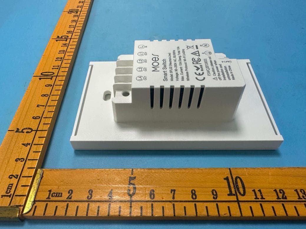
2AT8P-SFL02
Dec 23, 2025Smart Switch
Equipment Class
DTS - Digital Transmission System2AT8P-WP-USD
Jun 14, 2022Dimming plug
Equipment Class
DTS - Digital Transmission System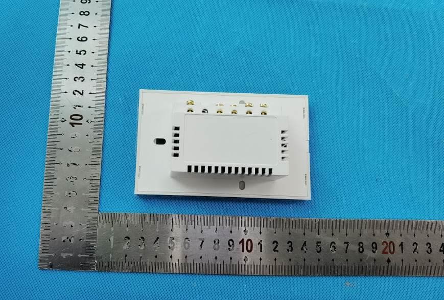
2AT8P-WSEUNX
Jan 10, 2021Smart Switch
Equipment Class
DTS - Digital Transmission System