2AT8Z-TCE7280Card reader
Shanghai 3Core technologies, Inc.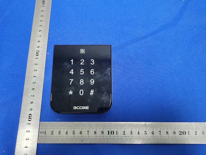
Click to zoom
Application Details
- Equipment Class
- DXX - Part 15 Low Power Communication Device Transmitter
- Date of Grant
- Sep 18, 2022
- Application Purpose
- Original Equipment
- Date of Application
- Sep 18, 2022
- Equipment Note
- Card reader
- Frequency Range
- 13.56000000 - 13.56000000
- Country
- China
Documents & Files
Document Text
Text extracted from the exhibit documents filed with the FCC. Open a document above to read the original.
Users Manual
3core reader TCE7280 Copyright @ 2019 3core technologies.Inc. 3core logo are registered trademarks of 3core technologies.Inc. ● Model:TCE7280 ● Reader output:Wiegand 26, Wiegand 32, Wiegand 34 ● Power requirement:12V DC ● Normal current consumption:60mA ● Activated current consumption:90mA ● Read range:0-60mm (0" - 2.4") (typically) ● Operating temperature:-15°C to + 55°C (5°F to 131°F) ● Relative humidity:90% max, operating non-condensing ● Size: 100×86×11mm HxWxD (Installed) ● IP Rating:IP 55 Optional extended function: ● Expansion module 26010EXB supports the function of Wiegand conversion to RS485 for Extend transmission distance 26011EXB supports the function of Wiegand conversion to RS232 or USB ● Configuration card Configuration card may be used to change the card setting, including Wiegand output (default as Wiegand32) and keyboard output (limited to reader with keyboard mode). The reader, after power-on self-test, accepts setting operation of configuration card. When the power-on reader reads the first non-configuration card, it stops accepting configuration operation of the card. In this case, it is necessary to make reconfiguration of reader, meaning Component 3CORE reader Installation Manual 4mm×40mm machine screw 3.5mm×40mm self-tapping machine screw Amount 1 1 2 4 Definition 485A 485B Wiegand1 BEEP Wiegand0 LED +12V GND Line color Yellow Orange White Blue Green Gray Red Black to power down and reader and power on again. FCC WARNING This device complies with part 15 of the FCC Rules. Operation is subject to the following two conditions: (1) this device may not cause harmful interference, and (2) this device must accept any interference received, including interference that may cause undesired operation. Any changes or modifications not expressly approved by the party responsible for compliance could void the user's authority to operate the equipment. NOTE: This equipment has been tested and found to comply with the limits for a Class B digital device, pursuant to Part 15 of the FCC Rules. These limits are designed to provide reasonable protection against harmful interference in a residential installation. This equipment generates, uses and can radiate radio frequency energy and, if not installed and used in accordance with the instructions, may cause harmful interference to radio communications. However, there is no guarantee that interference will not occur in a particular installation. If this equipment does cause harmful interference to radio or television reception, which can be determined by turning the equipment off and on, the user is encouraged to try to correct the interference by one or more of the following measures: -- Reorient or relocate the receiving antenna. -- Increase the separation between the equipment and receiver. -- Connect the equipment into an outlet on a circuit different from that to which the receiver is connected. -- Consult the dealer or an experienced radio/TV technician for help. To maintain compliance with FCC’s RF Exposure guidelines, This equipment should be installed and operated with minimum 20cm distance between the radiator and your body: Use only the supplied antenna. ● 型号:TCE7280 ● 输出格式:韦根26, 韦根32, 韦根34 ● 输入电压:12V 直流 ● 待机工作电流:60mA ● 任务工作电流:90mA ● 读卡距离:20-60mm (0.8" - 2.4") ● 使用环境温度界限:-15ºC 至 55ºC (5ºF 至 131ºF) ● 使用环境湿度界限:<90% max, ● 尺寸: 100×86×11mm HxWxD (安装后) ● 防护等级:IP55 可选扩展功能: ● 扩展模块 26010EXB支持Wiegand 到 RS485的转换功能,用于延长传输距离。 26011EXB支持Wiegand 到RS232 和USB的转换功能 ● 配置卡 可以使用配置卡来改变读卡器的设置,包括Wiegand输出(缺省为Wiegand32)和键盘输 出(只限于带键盘模式的读卡器)。读卡器上电自检之后,接受配置卡的配置操作。当读卡 器读到第一张非配置卡时,将停止接受配置卡的配置操作。如果,需要对读卡器重新配置, 需要对读卡器下电后重新上电。 部件 3CORE 读卡器 安装手册 4mm×40mm机制螺丝 3.5mm×40mm自攻机制螺丝 数量 1 1 2 4 定义: 485A 485B 韦根1 BEEP 韦根0 LED +12V GND 线色: 黄色 橙色 白色 蓝色 绿色 灰色 红色 黑色
Cover Letter(s)
Shanghai 3Core technologies, Inc. Agent Authorization Company: Shanghai 3Core technologies, Inc. Address: No.7, lane175, Wanhuangdu Road, Jingan District, Shanghai, PR China Product Name: Card reader Model Number(s): TCE7280, TEC7180 Product Description: Card reader We authorize MiCOM Labs Inc., 575 Boulder Court, Pleasanton, California 94566, USA, to act on our behalf on all matters concerning the certification of above named equipment. We declare that MiCOM Labs Inc. is allowed to forward all information related to the approval and certification of equipment to the regulatory agencies as required and to discuss any issues concerning the approval application. Any and all acts carried out by MiCOM Labs on our behalf shall have the same effect as acts of our own. Signature: Date: 2022-09-09 Name: XU BIN Title: Manager Company: Shanghai 3Core technologies, Inc.
Cover Letter(s)
Shanghai 3Core technologies, Inc. Model Difference Data:2022.09.09 Product description: Card reader Model name: TCE7280, TEC7180 Trade Name: 3CORE FCC ID: 2AT8Z-TCE7280 All the model are the same circuit and RF module, except model names . Regards Sincerely Client’s signature : Client’s name / title : XU BIN(Manager) Contact information / address:No.7, lane175, Wanhuangdu Road, Jingan District, Shanghai, PR China
Cover Letter(s)
Shanghai 3Core technologies, Inc. Office of Engineering Technology Federal Communications Commission 7435 Oakland Mills Road Columbia, MD 21046 USA Date: 2022/09/09 Subject; Request for Confidentiality FCC ID: 2AT8Z-TCE7280 To Whom It May Concern, Pursuant to the provisions of the Commission’s rules Title 47 Sections §0.457 and §0.459, we are requesting the Commission to withhold the following attachment(s) as confidential documents from public disclosure indefinitely. These documents contain detailed system and equipment descriptions and are considered as proprietary information in operation of the equipment. The public disclosure of these documents might be harmful to our company and would give competitors an unfair advantage in the market. Schematic Diagram Block Diagram Operational Description In additional to above mentioned documents, in order to comply with the marketing regulations in Title 47 CFR §2.803 and the importation rules in Title 47 CFR §2.1204, while ensuring that business sensitive information remains confidential until the actual marketing of newly authorized devices, we request Short Term Confidentiality of the following attachment(s); User Manual For 45 days, pursuant to Public Notice DA 04-1705. OR For 180 days pursuantto KDB 726920 D01. It is our understanding that all measurement test reports, FCC ID label format and correspondence during the certification review process cannot be granted as confidential documents and this information will be available for public review once the grant of equipment authorization is issued. Sincerely, Signature: Name: XU BIN Title: Manager
External Photos
External Photos
ID Label/Location Info
Model: TCE7280 FCC ID: 2AT8Z-TCE7280 Label Location
Internal Photos
Internal Photos ANT
Test Report
Report Tel: 4008-707-283 Web: http://www.ctb-lab.com Page 1 of 26 Shenzhen CTB Testing Technology Co., Ltd. Report No.: CTB220902048RFX TEST REPORT Product Name: Card reader FCC ID: 2AT8Z-TCE7280 Trademark: 3CORE Model Number: TCE7280, TEC7180 Prepared For: Shanghai 3Core technologies, Inc. Address: No.7, lane175, Wanhuangdu Road, Jingan District, Shanghai, PR China Manufacturer: Shenzhen Shannon Tech Co., Ltd Address: Room 518, Cybio electronic Building, Kejibei 2rd Road, Nanshan District, Shenzhen City, Guangdong Province Prepared By: Shenzhen CTB Testing Technology Co., Ltd. Address: Floor 1&2, Building A, No. 26 of Xinhe Road, Xinqiao Community, Xinqiao Street, Baoan District, Shenzhen, Guangdong, China. Sample Received Date: Aug. 17, 2022 Sample tested Date: Aug. 17, 2022 to Sep. 02, 2022 Issue Date: Sep. 02, 2022 Report No.: CTB220902048RFX Test Standards FCC Part15.225 ANSI C63.10:2013 Test Results PASS Remark: This is 13.56MHz radio test report. Compiled by: Reviewed by: Approved by: Chen Zheng Arron Liu Bin Mei / Director Note: If there is any objection to the inspection results in this report, please submit a written report to the company within 15 days from the date of receiving the report. The test report is effective only with both signature and specialized stamp. This result(s) shown in this report refer only to the sample(s) tested. Without written approval of Shenzhen CTB Testing Technology Co., Ltd. this report can’t be reproduced except in full. The tested sample(s) and the sample information are provided by the client. “*” indicates the testing items were fulfilled by subcontracted lab. “#” indicates the items are not in CNAS accreditation scope. Report Tel: 4008-707-283 Web: http://www.ctb-lab.com Page 2 of 26 Shenzhen CTB Testing Technology Co., Ltd. Report No.: CTB220902048RFX TABLE OF CONTENT TestReportDeclaration Page 1. VERSION ............................................................................................................................................... 4 2. TESTSUMMARY ................................................................................................................................... 5 3. MEASUREMENTUNCERTAINTY ......................................................................................................... 6 4. PRODUCT INFORMATION AND TESTSETUP .................................................................................... 7 4.1 ProductInformation ................................................................................................................................. 7 4.2 Test SetupConfiguration ........................................................................................................................ 7 4.3 SupportEquipment ................................................................................................................................. 7 4.4 TestMode ............................................................................................................................................... 8 4.5 TestEnvironment .................................................................................................................................... 8 5. TEST FACILITY AND TEST INSTRUMENTUSED ................................................................................ 9 5.1 TestFacility ............................................................................................................................................. 9 5.2 Test InstrumentUsed .............................................................................................................................. 9 6. AC POWER LINE CONDUCTEDEMISSION ....................................................................................... 11 6.1 Block Diagram Of TestSetup ................................................................................................................ 11 6.2 Limit ..................................................................................................................................................... 11 6.3 Testprocedure ...................................................................................................................................... 11 6.4 TestResult ............................................................................................................................................ 13 7. RADIATEDEMISSION ......................................................................................................................... 14 7.1 Block Diagram Of TestSetup ................................................................................................................ 14 7.2 Limit ..................................................................................................................................................... 14 7.3 Testprocedure ...................................................................................................................................... 15 7.4 TestResult ............................................................................................................................................ 16 8. FREQUENCYTOLERANCE ................................................................................................................ 20 8.1 Block Diagram Of TestSetup ................................................................................................................ 20 8.2 Limit ..................................................................................................................................................... 20 8 .3 Testprocedure ...................................................................................................................................... 20 8.4 TestResult ............................................................................................................................................ 21 9. OCCUPIEDBANDWIDTH .............................................…
Text truncated - open the document above for the full version.
Test Report
ANT PHTOT L W H 70mm±0.2 60mm±0.2 0.1mm±0.1
Test Setup Photos
Radiated Emission Below 1G 9KHz-30MHz
Contact Information
Applicant
Bin Xu(Manage)
Technical Contact
Test Firm
Shenzhen CTB Testing Technology Co., Ltd.Rita Xiao
[email protected]86-13538218145
Technical Specifications
| # | Rule Parts | Frequency Range | Power Output |
|---|---|---|---|
| 1 | 15C | 13.56 MHz - 13.56 MHz | - |