2ATB3-QCXSTM32WBCordless Precision Fastening Screw Driver Tool Controller
Ingersoll-Rand Industrial U.S. Inc.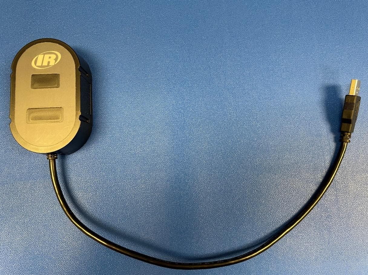
Click to zoom
Application Details
- Equipment Class
- DTS - Digital Transmission System
- Date of Grant
- Sep 25, 2022
- Application Purpose
- Original Equipment
- Date of Application
- Sep 25, 2022
- Equipment Note
- Cordless Precision Fastening Screw Driver Tool Controller
- Frequency Range
- 2405.00000000 - 2475.00000000
- Country
- United States
Documents & Files
Document Text
Text extracted from the exhibit documents filed with the FCC. Open a document above to read the original.
Users Manual
47649557001 Edition 6 September 2022 Save These Instructions Cordless Tool Controller INSIGHTqcx Product Information Προδιαγραφές προϊόντος EL Especificações do Produto PT Tuote-erittely FI Produktspesifikasjoner NO Produktspecifikationer SV Produktspecifikationer DA Productinformatie NL Technische Produktdaten DE Specifiche prodotto IT Spécifications du produit FR Especificaciones del producto ES Product Information EN SL Specifikacije izdelka SK Špecifikácie produktu CS Specifikace výrobku ET Toote spetsifikatsioon HU A termék jellemzői LT Gaminio techniniai duomenys LV Ierices specifikacijas RU Технические характеристики изделия ZH 产品信息 Informacje o produkcie PL JA 製品仕様 KO 제품 상세 Информация за Продукта BG Informaţii Privind Produsul RO Ürün Bilgisi TR HR Podaci o proizvodu 2 47649557001_ed6 Product Safety Information EN Intended Use: These Cordless Tool Controllers are designed to communicate process data and signals between specific Ingersoll Rand equipment and compatible user equipment such as PLCs, bar code scanners and printers. Power SupplyInput VoltageOutput Voltage 24V DC 100-240 V ~ 50-60 Hz, 80 A Max. @ 240 V ~24.0V DC, 2.1A 5015451 For additional information, refer to Communication Module for Cordless Tools Safety Information Manual 47114541, User Manuals 48619696 and 48619852. This device conforms to UL STD. 60950-1 & 62368-1; certified to CSA STD. C22.2 No. 60950-1 & 62368-1. Manuals can be downloaded from ingersollrand.com Información de seguridad sobre el producto ES Uso indicado: Estos controladores para herramientas inalámbricas se han diseñado para comunicar las señales y los datos de los procesos entre equipos específicos de Ingersoll Rand y equipos compatibles de los usuarios, como controladores PLC, escáneres de códigos de barras e impresoras. Suministro de energíaVoltaje de entradaVoltaje de salida 24V DC 100-240 V ~ 50-60 Hz, 80 A Max. @ 240 V ~24.0V DC, 2.1A 5015451 Para obtener información adicional, consulte la sección relativa al módulo de comunicación en el Manual de información de seguridad de herramientas inalámbricas 47114541 y en los Manuales de usuario 48619696 y 48619852. Este dispositivo cumple la norma UL STD. 60950-1 & 62368-1 y está certificado por la norma CSA STD. C22.2 nº 60950-1 & 62368-1. Los manuales se pueden descargar desde ingersollrand.com Informations de Sécurité du Produit FR Utilisation Prévue: Ces contrôleurs d’outils sans fil sont conçus pour transmettre des données et signaux liés au processus entre un équipement Ingersoll Rand en particulier et un équipement utilisateur compatible, comme des automates programmables (PLC), des scanners de codes-barres et des imprimantes. Alimentation électriqueTension d’entréeTension de sortie 24V DC 100-240 V ~ 50-60 Hz, 80 A Max. @ 240 V ~24.0V DC, 2.1A 5015451 Pour obtenir des informations supplémentaires, veuillez vous référer au manuel d’informations de sécurité des modules de communication pour les outils sans fil n°47114541 ainsi qu’aux manuels d’utilisateur n°48619696 et n°48619852. Cet appareil est conforme à la norme UL 60950-1 & 62368-1; certifié par la norme CSA C22.2 N°60950-1 & 62368-1. Vejledninger kan downloades fra ingersollrand.com Informazioni Sulla Sicurezza del Prodotto IT Destinazione d’uso: Questi dispositivi di controllo per utensili senza fili sono progettati per comunicare dati di processo e segnali tra specifiche apparecchiature Ingersoll Rand e apparecchiature compatibili degli utenti, quali PLC, scanner di codici a barre e stampanti. AlimentazioneTensione di ingressoTensione di uscita 24V DC 100-240 V ~ 50-60 Hz, 80 A Max. @ 240 V ~24.0V DC, 2.1A 5015451 47649557001_ed6 3 Per informazioni aggiuntive, fare riferimento al manuale contenente le informazioni sulla sicurezza relativa al modulo di comunicazione per utensili portatili 47114541, manuali utente 48619696 e 48619852. Il dispositivo è conforme a UL STD. 60950-1 & 62368-1; certificazione CSA STD. C22.2 N. 60950-1 & 62368-1. Los manuales pueden descargarse desde ingersollrand.com Hinweise zur Produktsicherheit DE Vorgesehene Verwendung: Diese Steuerungen für Akkuwerkzeuge ermöglichen die Kommunikation von Prozessdaten und Signalen zwischen bestimmten Ingersoll Rand Geräten und kompatiblen Bedienergeräten, wie PLCs, Barcodescannern und Druckern. StromversorgungEingangsspannungAusgangsspannung 24V DC 100-240 V ~ 50-60 Hz, 80 A Max. @ 240 V ~24.0V DC, 2.1A 5015451 Weitere Informationen finden Sie im Informationshandbuch für das Kommunikationsmodul für kabellose Geräte 47114541 sowie in den Bedienungsanleitungen 48619696 und 48619852. Dieses Gerät entspricht dem UL STD. 60950-1 & 62368-1; zertifiziert nach CSA STD. C22.2 Nr. 60950-1 & 62368-1. Les manuels peuvent être téléchargés sur le site ingersollrand.com Productveiligheidsinformatie NL Bedoeld Gebruik: Met deze draadloze gereedschapscontrollers kunnen procesgegevens en -signalen tussen specifieke Ingersoll Rand-apparatuur en compatibele apparatuur van de gebruiker zoals PLC’s, barcodescanners en printers gecommuniceerd worden. VoedingIngangsspanning Uitgangsspanning 24V DC 100-240 V ~ 50-60 Hz, 80 A Max. @ 240 V ~24.0V DC, 2.1A 5015451 Meer informatie vindt u in de Handleiding met veiligheidsinformatie voor de communicatiemodule voor snoerloos gereedschap 47114541 en de Gebruikershandleidingen 48619696 en 48619852. Dit apparaat voldoet aan UL STD. 60950-1 & 62368-1; gecertificeerd conform CSA STD. C22.2 No. 60950-1 & 62368-1. Ohjeet voi ladata osoitteesta ingersollrand.com Produktsikkerhedsinformation DA Anvendelsesområder: Disse kontrolenheder til ledningsfrit værktøj er designet til at sende og modtage procesdata og signaler mellem specifikt Ingersoll Rand-udstyr og kompatibelt brugerudstyr som f.eks. PLC’er, stregkodelæsere og printere. StrømforsyningIndgangsspændingUdgangsspænding 24V DC 100-240 V ~ 50-60 Hz, 80 A Max. @ 240 V ~24.0V DC, 2.1A 5015451 Yderligere oplysninger findes i sikkerhedsvejledningen til kommunikationsmodul for trådløst værktøj 47114541, bruge…
Text truncated - open the document above for the full version.
Users Manual
Artwork for Webcard insert included with the QCX system Note: QR code goes directly to the setup/instructions
Users Manual
IRToolHelp > Assembly Solutions > Cordless Precision Fastening > How-To Pairing a QXX tool with the INSIGHTqcx Eng-Hua Yap (LAg) 6 months ago· Updated Follow This article demonstrates how to pair a QXX tool with the INSIGHTqcx controller. VIDEO INSTRUCTIONS: How to Pair an Ingersoll Rand QX tool to an Ingersoll Rand IHow to Pair an Ingersoll Rand QX tool to an Ingersoll Rand I...... Select Language ▼ Product/Business: Power Tools ▾ What can we help you find? SEARCH Articles in this section WRITTEN INSTRUCTIONS: Pre-requisite: The QXX tool firmware needs to be compatible with the INSIGHTqcx controller. Please connect the QXX tool using a USB cable to the INSIGHTqcx controller to check and update the firmware. 1. Check that the wireless radio is enabled on QXX. From the back cap, go to the passcode screen. Enter the 4 digit passcode (by default FFFF). Press the left button to view the Wireless status. Enable Wireless if it is currently disabled. 2. From the INSIGHTqcx controller, please login as needed. 3. Follow the steps below to pair a QXX tool with an INSIGHTqcx Cordless Controller. Note: User can also follow a guided video on the Wireless Tool Pairing screen for the same instruction. StepsInstruction 1. Click on the Wireless Tool icon 2.Click on the Pair button on the screen 3. Click and hold the left arrow and ok button for 3 seconds on the tool backcap 4Wait for the LED lights on the tool to blink 5When pairing is successful, the Wireless Tool Icon will turned green. Frequently Asked Questions (FAQ): 1. Why is the Wireless Icon in Red? Answer: The wireless tool icon will be in red when a paired tool is in idle or sleep mode. Please pull trigger to wake the tool. Shortly after the tool is active, the wireless tool icon will be green again. 2. I have pressed the left and ok button but tool still can’t pair. There is no blinking LED. What should I do? Answer: Please double check that the Wireless Radio is turned on. Follow these instruction to check wireless status: From the back cap, go to the passcode screen Enter the 4 digit passcode (by default FFFF). Press the left button to view the Wireless status. Enable Wireless if it is currently disabled 3. I have just updated the tool firmware but the Wireless Tool screen is showing that the tool still needs to be updated. Answer: User may have to update both the MCE and Display which may require 2 separate updates. Please make sure both MCE and Display have been updated. 4. MCE version is empty or showing "0.0.0" Answer: The MCE info is not available. This is because the tool might be in Idle mode. Pull the trigger to wake up the tool and check again. Was this article helpful? Yes No 0 out of 1 found this helpful Have more questions? Submit a request Return to top Recently viewed articles INSIGHT Connect Installing, Steps to pair a QX tool for the first time to INSIGHT Connect. INSIGHT Connect Virtual Programming INSIGHT Connect Overview QX Connect Menu Map Related articles Programming a QXX tool wirelessly with an INSIGHTqcx Upgrading QX Tool firmware using the INSIGHTqcx Updating the firmware on an INSIGHTqcx Setting Up Ethernet IP on the INSIGHTqcx Firmware Version 1.1.6 for INSIGHTqcx (not most current) Comments 0 comments Be the first to write a comment. Can't find what you're looking for? SUBMIT A REQUEST Explore our family of brands © Ingersoll-Rand plc, 2021 Ingersoll Rand Inc. (NYSE:IR), driven by an entrepreneurial spirit and ownership mindset, is dedicated to helping make life better for our employees, customers and communities. Customers lean on us for our technology-driven excellence in mission-critical flow creation and industrial solutions across 40+ respected brands where our products and services excel in the most complex and harsh conditions. Our employees develop customers for life through their daily commitment to expertise, productivity and efficiency. For more information, visit www.IRCO.com. Privacy Terms
Cover Letter(s)
April 5, 2022 Attention: Application Examiner RE: Request for Confidentiality Applicant: Ingersoll Rand Inc. FCC ID: 2ATB3-QCXSTM32WB To Whom It May Concern: Request is hereby submitted by Ingersoll Rand Inc. to withhold permanently from public review certain portions of this application for equipment certification for the referenced FCC identifiers. This request for confidentiality is made pursuant to 47 CFR 0.457(d) and 0.459 of the FCC Rules. In particular, the following sections of the application are to be kept permanently confidential: Schematics Detailed Block diagrams Detailed Operational/Functional Description Parts list Rationale for request for confidentiality: Ingersoll Rand Inc. has invested considerable time and materials in research and development to produce the referenced product. Permanent confidentiality: Disclosure of the permanently confidential portions of this application to competitors would not only give them significant competitive advantages in developing similar products, but would also disclose successful implementation of unpublished, leading edge technology developed by us. Sincerely, Andres Cruz Electrical Engineer Ingersoll Rand Inc. Ingersoll Rand Inc. 800-A Beaty Street Davidson, NC 28036 USA
Cover Letter(s)
April 5, 2022 Federal Communications Commission 445 12 th Street SW Washington, DC 20554 Subject: Limited Agency Agreement Ingersoll Rand Inc. FCC ID: 2ATB3-QCXSTM32WB To Whom It May Concern: We, Ingersoll Rand Inc, hereby authorized Intertek Testing Services to act as our Agent for the purpose of preparing application for FCC ID number 2ATB3-QCXSTM32WB under all applicable parts of the FCC rules and regulations. The effective date of this limited agency agreement is April 5, 2022. The Limited Agency Agreement expires on December 31, 2022 unless sooner terminated or extended by written notice to Intertek Testing Services and the Federal Communications Commission. This is to advise that we are in full compliance with the Anti-Drug Abuse Act. The applicant is not subject to a denial of federal benefits pursuant to Section 5301 of the Anti-Drug Act of 1988, 21 U.S.C. 862, and no party to the application is subject to a denial of federal benefits pursuant to that section. If you have any questions or comments, please do not hesitate to contact me. Sincerely, Andres Cruz Electrical Engineer Ingersoll Rand Inc. 800-A Beaty Street Davidson, NC 28036 USA
External Photos
External Photos - QCX External Radio Module Ingersoll Rand Inc. Front side w/cable Front side Back Side with Bracket Side Profile
ID Label/Location Info
ALERT Use .AI (Adobe Illustrator) file for production. Monitor display of .pdf (Adobe Acrobat) may be distorted. View a printed image for better clarity. QCX Radio Module Input: 5V USB Lot: TA-VD1T-888-2C XXXXXXXXX INGERSOLL RAND FCC ID: 2ATB3-QCXSTM32WB IC: 25117-QCXSTM32WB PRINT IMAGE: (PRODUCTION ART) LAYOUT/COLOR PROOF: (DO NOT PRINT) 100% Process Black Master Artwork Proprietary Property of Ingersoll Rand Part Number: QCX-300-2C Nomenclature: QCX-300-2C Artwork Number: QCX-300-2CAW Revision: C Trim Size: 12.7mm X 25.4 IMPORTANT - Refer to engineering drawing for production specifications. • For four-color process (CMYK) printing, match output to Pantone color swatches listed below. • A print proof and any deviation of color or change affecting master artwork must be approved by Ingersoll Rand Graphic Design prior to production. • Provide first-run production part samples (2+) to Ingersoll Rand Graphic Design for final review. Designer: Jackie Sherrer Application: Adobe Illustrator CC (macOS) COLOR SWATCHES: Black Text prints 100% Process Black. Cyan Text is Variable info, entered at plant. LOT = Serial Number shown as WW= Week, YY=Year and 12345=Serial Number
ID Label/Location Info
SCREW, M2.2 X 6 4 INSIGHT QCX RADIO HOUSING BOTTOM 1 INSIGHT QCX RADIO HOUSING TOP 1 THREAD FORMING SCREW 6 INSIGHT QCX RF HOUSING LABEL 1 RADIO MODULE LABEL 1 INSIGHT QCX RF MOUTING BRACKET 1 INSIGHT QCX RF USB CABLE 1 INSIGHT QCX RF BOARD ASSEMBLY 1 4 2 3 8 1 4 9 7 5 6 87654 3 21 8765123 D C B A D C A B 4 COPYRIGHT @ 2022 ALL RIGHTS RESERVED CAD GENERATED DRAWING, NO MANUAL REVISIONS ALLOWED DRAWING CONFORMS TO DO NOT SCALE DRAWING UNLESS OTHERWISE SPECIFIED PRINTED DOCUMENT IS UNCONTROLLED UNLESS OTHERWISE SPECIFIED: - REMOVE ALL BURRS AND SHARP CORNERS - WELD SYMBOLS TO BE IN ACCORDANCE WITH ANSI/AWS A2.4 WARNING: THE EXPORT OR REEXPORT OF THIS DRAWING OR A PRODUCT PRODUCED BY THIS DRAWING IS SUBJECT TO U.S. EXPORT ADMINISTRATION REGULATIONS & OTHER APPLICABLE GOVERNMENT RESTRICTIONS OR REGULATIONS. ESTIMATED WEIGHT (KG UNLESS OTHERWISE SPECIFIED) A1 NAME SIZE MODEL SHEET REVISION SCALE PROPRIETARY NOTICE: THIS DRAWING CONTAINS CONFIDENTIAL AND TRADE SECRET INFORMATION, IS THE PROPERTY OF THE COMPANY., AND IS GIVEN TO THE RECEIVER IN CONFIDENCE. THE RECEIVER BY RECEPTION AND RETENTION OF THE DRAWING ACCEPTS THE DRAWING IN CONFIDENCE AND AGREES THAT, EXCEPT AS AUTHORIZED IN WRITING BY THE COMPANY. IT WILL (1) NOT USE THE DRAWING OR ANY COPY THEREOF OR THE CONFIDENTIAL OR TRADE SECRET INFORMATION THEREIN; (2) NOT COPY THE DRAWING; (3) NOT DISCLOSE TO OTHERS EITHER THE DRAWING OR THE CONFIDENTIAL OR TRADE SECRET INFORMATION THEREIN; AND (4) UPON COMPLETION OF THE NEED TO RETAIN THE DRAWING, OR UPON DEMAND, RETURN THE DRAWING, ALL COPIES THEREOF, AND ALL MATERIAL COPIED THEREFROM. COMPANY PART NO. INGERSOLL RAND - POWER TOOLS - METRIC UNSPECIFIED TOLERANCES: X +/- 1.0 X.X +/- 0.5 X.XX +/- 0.25 ANGLES +/- 1.0 MACHINED SURFACES 3.2 MAX ® CRITICAL TO QUALITY UNLESS OTHERWISE SPECIFIED DIMENSIONS ARE IN MILLIMETERS PER ASME Y14.5M-1994 STANDARD TOLERANCES R INSIGHT QCX RF MODULE ASSEMBLY INSIGHT QCX RF MODULE ASSEMBLY -C 2.002 OF 1 For Internal Use : Model = TA-VD1T-888-2C | ASSEM | C.0 | Nagendra Kumar | 19-May-22 12:21:42 PM | Design Drawing = TA-VD1T-888-2C | DRAW | C.0 | Nagendra Kumar | 19-May-22 12:21:42 PM | Design C.0(C.0) REVISIONS APPROVEDDRAWNDATEDESCRIPTIONECNREVZONE JOHN.LNAGENDRA20-JAN-22RELEASE FOR PROTOTYPE1454797A JOHN.LNAGENDRA04-MAR-22ORIGINAL RELEASE1455436B JOHN.LNAGENDRA19-MAY-22ADDED LABEL2304923C ASME Y14.5M - 1994 INGERSOLL RAND INGERSOLL RAND TA-VD1T-888-2C NOMENCLATURE Detail Drawing DRAWING TYPE 1-20-2022JOHN.L DATEAPPROVED 1-20-2022SIJI DATECHECKED 1-20-2022NAGENDRA DATEDRAWN THIRD ANGLE PROJECTION TA-VD1T-888-2C TA-VD1T-888-2CPART_NO Table Version 3.2 BOM FOR TA-VD1T-888-2C SHT/ZMATL. DESCRIPTION NOMENCLATURE PART NO.QTY.ITEM SCREW, M2.2 X 6VP1-1424709580741 INSIGHT QCX RADIO HOUSING BOTTOMQCX-40-RBQCX-40-RB12 INSIGHT QCX RADIO HOUSING TOPQCX-40-RTQCX-40-RT13 THREAD FORMING SCREWQCX-78-2CQCX-78-2C64 INSIGHT QCX RF HOUSING LABELQCX-300-2CQCX-300-2C15 RADIO MODULE LABELQCX-301-2CQCX-301-2C16 INSIGHT QCX RF MOUTING BRACKETQCX-366-RPQCX-366-RP17 INSIGHT QCX RF USB CABLEQCX-CABLE-15-LUSBQCX-CABLE-15-LUSB18 INSIGHT QCX RF BOARD ASSEMBLYTA-VD1T-499-2CTA-VD1T-499-2C19 PACKAGING BOM (SUBSTITUTES ALLOWED) ITEMPART NAMEDESCRIPTIONMFR NAMEPART NO.QTY 1ESD BAG5" X 6" TRANSPARENT METAL-IN STATIC SHIELDING BAG TECHNI-TOOL295ST0561 2ESD LABELESD SUSCEPTIBILITY SYMBOL; JEDEC/EIA471 2" X 2 "TECHNI-TOOL758ST7221 3ROHS LABELSCC LEAD FREE LABEL, RoHS COMPLIANT, 1-3/4" X 1-3/4"3M800009177591 4ESD BAG REV LABELZEBRA (SEE LABEL EXAMPLE FOR TEXT)ZEBRALV-56001, RED1 ITEM ORDERING INSTUCTIONS: IN ADDITION TO THIS DRAWING AND RELATED DOCUMENTS FOR ALL BOM STRUCTURE ITEMS, PROVIDE MANUFACTURING VENDOR WITH LATEST RELEASED VERSION ZIP FILE DATA CONTAINED IN THE FOLLOWING ITEMS: TM-VD1T-499-2C, MANUFACTURING DATA PACKAGING INSTRUCTIONS: PLACE ASSEMBLED BACK CAP ITEM IN ESD BAG WITH APPROPRIATE LABELING AS SPECIFIED IN PACKAGING BOM TABLE. SEAL ESD BAG BY FOLDING OVER TOP PORTION AND SECURE FLAP WITH ESD LABEL. FORMAT OF THE "ESD BAG REV LABEL" SHALL BE PRODUCED PER "LABEL EXAMPLE" ILLUSTRATION. PROVIDED BELOW. NOTE: CHARACTERS ILLUSTRATED AS "X" TO BE REPLACED WITH CURRENT REVISION LEVEL. LABEL EXAMPLE: SOURCE CANNOT BE CHANGED WITHOUT ENGINEERING APPROVAL SPECIFICATIONS: TA-VD1T-499-2C, REV-X, LOT NO_ _ _ _ _ _ _ TA-VD1T-888-2C, REV-X PCBA LOT NUMBER 4X TORQUE 0.23-0.27 Nm 4X TORQUE 0.8-1.2 Nm 2X TORQUE 0.8-1.2 Nm 1 2 3 4 2 1 3 C A A 87654 3 21 8765123 D C B A D C A B 4 UNLESS OTHERWISE SPECIFIED PRINTED DOCUMENT IS UNCONTROLLED NAME A1 SCALE SHEET REVISION SIZE NOMENCLATURE PROPRIETARY NOTICE: THIS DRAWING CONTAINS CONFIDENTIAL AND TRADE SECRET INFORMATION, IS THE PROPERTY OF THE COMPANY, AND IS GIVEN TO THE RECEIVER IN CONFIDENCE. THE RECEIVER BY RECEPTION AND RETENTION OF THE DRAWING ACCEPTS THE DRAWING IN CONFIDENCE AND AGREES THAT, EXCEPT AS AUTHORIZE D IN WRITING BY THE COMPANY IT WILL (1) NOT USE THE DRAWING OR ANY COPY THEREOF OR THE CONFIDENTIAL OR TRADE SECRET INFORMATION THEREIN; (2) NOT COPY THE DRAWING; (3) NOT DISCLOSE TO OTHERS EITHER THE DRAWING OR THE CONFIDENTIAL OR TRADE SECRET INFORMATION THEREIN; AND (4) UPON COMPLETION OF THE NEED TO RETAIN THE DRAWING, OR UPON DEMAND, RETURN THE DRAWING, ALL COPIES THEREOF, AND ALL MATERIAL COPIED THEREFROM. COMPANY PART NO. 93.26 77.99 47.29 INSIGHT QCX RF MODULE ASSEMBLY INSIGHT QCX RF MODULE ASSEMBLY R C 2.00TA-VD1T-888-2C2 OF 2 C.0(C.0) INGERSOLL RAND TA-VD1T-888-2C TA-VD1T-888-2CPART_NO A-ASECTION APPLY 3M HOT MELT ADHESIVE 3748 ON THEESE LOCATIONS
Internal Photos
Internal Photos _ QCX External Radio Module Ingersoll Rand Inc. Back side (PCA) Front side (PCA) Ceramic Chip Antenna ANT1608LL14R2400A Back Side (PCA) in Enclosure Ceramic Chip Antenna ANT1608LL14R2400A
RF Exposure Info
INGERSOLL-RAND INDUSTRIAL U.S., INC. MPE REPORT SCOPE OF WORK MPE CALCULATION – MODEL QCXD21 (Zigbee – IEEE 802.15.4 USB Dongle) REPORT NUMBER 105001833BOX-006MPE ISSUE DATE [REVISED DATE] June 9, 2022 Original Issue DOCUMENT CONTROL NUMBER Non-Specific Radio Report Shell Rev. August 2020 © 2020 INTERTEK Non-Specific Radio Report Shell Rev. August 2020 Page 2 of 9 Client: Ingersoll-Rand Industrial U.S., Inc. – Model: QCXD21 (Zigbee – IEEE 802.15.4 USB Dongle) MPE REPORT (FULL COMPLIANCE) Report Number: 105001833BOX-006MPE Project Number: G105001833 Report Issue Date: June 9, 2022 Model(s) Evaluated: QCXD21 (Zigbee – IEEE 802.15.4 USB Dongle Standards: FCC Part 1 Subpart I, October 2019 Procedures Implementing the National Environmental Policy Act of 1969 §1.1307 Actions that may have a significant environmental effect, for which Environmental Assessments (EAs) must be prepared. ISED RSS-102 Issue 5, March 19, 2015 Radio Frequency (RF) Exposure Compliance of Radiocommunication Apparatus (All Frequency Bands) Tested by: Client: Intertek Testing Services NA, Inc. 70 Codman Hill Road Boxborough, MA 01719 USA Ingersoll-Rand Industrial U.S., Inc. 800-E Beaty Street Davidson, NC 28036 USA Report prepared by Report reviewed by Kouma Sinn / EMC Engineering Supervisor Vathana Ven / EMC Engineering Supervisor This report is for the exclusive use of Intertek's Client and is provided pursuant to the agreement between Intertek and its Client. Intertek's responsibility and liability are limited to the terms and conditions of the agreement. Intertek assumes no liability to any party, other than to the Client in accordance with the agreement, for any loss, expense or damage occasioned by the use of this report. Only the Client is authorized to permit copying or distribution of this report and then only in its entirety. Any use of the Intertek name or one of its marks for the sale or advertisement of the tested material, product or service must first be approved in writing by Intertek. The observations and test results in this report are relevant only to the sample tested. This report by itself does not imply that the material, product, or service is or has ever been under an Intertek certification program. Intertek Report Number: 105001833BOX-006MPE Issued: 06/09/2022 Non-Specific Radio Report Shell Rev. August 2020 Page 3 of 9 Client: Ingersoll-Rand Industrial U.S., Inc. – Model: QCXD21 (Zigbee – IEEE 802.15.4 USB Dongle) Table of Contents 1 Introduction and Conclusion .............................................................................................................. 4 2 Evaluation Summary ........................................................................................................................... 4 3 Client Information ................................................................................................................................ 5 4 Description of Equipment Under Test and Variant Models ............................................................. 5 5 Power Density Calculation .................................................................................................................. 6 6 ISED RSS-102 Issue 5 §2.5.2 Exemption ........................................................................................... 8 7 Revision History ................................................................................................................................... 9 Intertek Report Number: 105001833BOX-006MPE Issued: 06/09/2022 Non-Specific Radio Report Shell Rev. August 2020 Page 4 of 9 Client: Ingersoll-Rand Industrial U.S., Inc. – Model: QCXD21 (Zigbee – IEEE 802.15.4 USB Dongle) 1 Introduction and Conclusion This evaluation report covers for a mobile device subject to routine environmental evaluation for RF exposure. A mobile device is defined as a transmitting device designed to generally be used in such a way that a separation distance of at least 20 centimeters is normally maintained between the transmitter’s radiating structurer(s) and the body of the user or nearby persons. The evaluation indicated in section 2.0 were performed on the product constructed as described in section 4.0. The remaining sections are the verbatim text from the actual evaluation during the investigation. These sections include the evaluation name, the specified Method, and Results. No additions, deviations, or exclusions have been made from the standard(s) unless specifically noted. Based on the results of our investigation, we have concluded the product evaluated complies with the requirements of the standard(s) indicated. The results obtained in this report pertain only to the item(s) evaluated. Intertek does not make any claims of compliance for samples or variants which were not evaluated. 2 Evaluation Summary Section Test full name Result 3 Client Information - 4 Description of Equipment Under Evaluation and Variant Models - 5 System Setup and Method - 6 Power Density Calculation (FCC §1.1310; ISED RSS-102 Issue 5) Compliant 7 Revision History - Intertek Report Number: 105001833BOX-006MPE Issued: 06/09/2022 Non-Specific Radio Report Shell Rev. August 2020 Page 5 of 9 Client: Ingersoll-Rand Industrial U.S., Inc. – Model: QCXD21 (Zigbee – IEEE 802.15.4 USB Dongle) 3 Client Information This EUT was tested at the request of: Client: Ingersoll-Rand Industrial U.S., Inc. 800-E Beaty Street Davidson, NC 28036 USA Contact: John Linehan Telephone: Not provided Fax: Not provided Email: [email protected] 4 Description of Equipment Under Test and Variant Models Manufacturer: Ingersoll-Rand Industrial U.S., Inc. 800-E Beaty Street Davidson, NC 28036 USA Equipment Under Test Description Manufacturer Model Number Serial Number Zigbee (IEEE 802.15.4) USB Dongle Ingersoll-Rand Company QCXD21 (USB Dongle) *BOX220506946-002 *Shipping track number issued by Intertek. Description of Equipment Under Test (provided by client) The equipment under test is Zigbee (IEEE 802.15.4) USB Dong…
Text truncated - open the document above for the full version.
Test Report
INGERSOLL-RAND INDUSTRIAL U.S., INC. EMISSIONS TEST REPORT SCOPE OF WORK EMISSIONS TESTING – MODEL QCXD21 (Zigbee – IEEE 802.15.4 USB Dongle) REPORT NUMBER 105001833BOX-006 ISSUE DATE [REVISED DATE] June 2, 2022 Original Issue DOCUMENT CONTROL NUMBER Non-Specific Radio Report Shell Rev. August 2020 © 2020 INTERTEK Non-Specific Radio Report Shell Rev. August 2020 Page 2 of 87 Client: Ingersoll-Rand Industrial U.S., Inc. – Model: QCXD21 (Zigbee – IEEE 802.15.4 USB Dongle) EMISSIONS TEST REPORT (FULL COMPLIANCE FOR LIMITED SINGLE-MODULAR TRANSMITTER) Report Number: 105001833BOX-006 Project Number: G105001833 Report Issue Date: June 2, 2022 Model(s) Tested: QCXD21 (Zigbee – IEEE 802.15.4 USB Dongle) Model(s) Partially Tested: None Model(s) Not Tested but declared equivalent by the client: None Standards: CFR47 FCC Part 15.247 Subpart C: 05/2022, CFR47 FCC Part 15 Subpart B: 05/2022, RSS-247 Issue 2 February 2017, ISED ICES-003 Issue 7 October 2020, RSS-Gen Issue 5 April 2018, KDB 558074 D01 15.247 Meas Guidance v05r02: 04/2019 Tested by: Client: Intertek Testing Services NA, Inc. 70 Codman Hill Road Boxborough, MA 01719 USA Rand Industrial U.S., Inc. 800-E Beaty Street Davidson, NC 28036 USA Report prepared by Report reviewed by Kouma Sinn / EMC Engineering Supervisor Vathana Ven / EMC Engineering Supervisor This report is for the exclusive use of Intertek's Client and is provided pursuant to the agreement between Intertek and its Client. Intertek's responsibility and liability are limited to the terms and conditions of the agreement. Intertek assumes no liability to any party, other than to the Client in accordance with the agreement, for any loss, expense or damage occasioned by the use of this report. Only the Client is authorized to permit copying or distribution of this report and then only in its entirety. Any use of the Intertek name or one of its marks for the sale or advertisement of the tested material, product or service must first be approved in writing by Intertek. The observations and test results in this report are relevant only to the sample tested. This report by itself does not imply that the material, product, or service is or has ever been under an Intertek certification program. Intertek Report Number: 105001833BOX-006 Issued: 06/02/2022 Non-Specific Radio Report Shell Rev. August 2020 Page 3 of 87 Client: Ingersoll-Rand Industrial U.S., Inc. – Model: QCXD21 (Zigbee – IEEE 802.15.4 USB Dongle) Table of Contents 1 Introduction and Conclusion .............................................................................................................. 4 2 Test Summary ...................................................................................................................................... 4 3 Client Information ................................................................................................................................ 5 4 Description of Equipment Under Test and Variant Models ............................................................. 5 5 System Setup and Method .................................................................................................................. 7 6 Maximum Peak Output Power ............................................................................................................ 8 7 6 dB Bandwidth and Occupied Bandwidth ..................................................................................... 13 8 Maximum Power Spectral Density ................................................................................................... 19 9 Band Edge Compliance ..................................................................................................................... 23 10 Transmitter spurious emissions ................................................................................................... 33 11 Digital Device and Receiver Radiated Spurious Emissions ...................................................... 74 12 AC Mains Conducted Emissions .................................................................................................. 82 13 Revision History ............................................................................................................................. 87 Intertek Report Number: 105001833BOX-006 Issued: 06/02/2022 Non-Specific Radio Report Shell Rev. August 2020 Page 4 of 87 Client: Ingersoll-Rand Industrial U.S., Inc. – Model: QCXD21 (Zigbee – IEEE 802.15.4 USB Dongle) 1 Introduction and C…
Text truncated - open the document above for the full version.
Contact Information
Applicant
William M Ball(Electronics Life Cycle Engineering Manager)
Test Firm
Intertek Testing Services NA Inc.Yaqing Liu
[email protected]9786358662
Technical Specifications
| # | Rule Parts | Frequency Range | Power Output |
|---|---|---|---|
| 1 | 15C | 2.40 GHz - 2.48 GHz | 3.50 mW |
Other Applications from Ingersoll-Rand Industrial U.S. Inc.
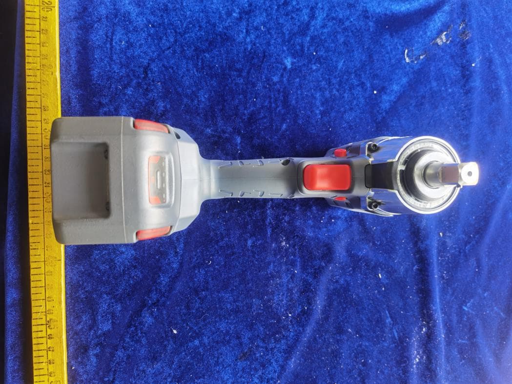
2ATB3-RTSSTM55WB
Jul 08, 2024Mechanical Pulse Wrench
Equipment Class
DTS - Digital Transmission System