2ATGY-AWC1070Wireless Charging Stand and Pad
UBIO LABS, INC.
Click to zoom
Application Details
- Equipment Class
- DCD - Part 15 Low Power Transmitter Below 1705 kHz
- Date of Grant
- Apr 05, 2020
- Application Purpose
- Original Equipment
- Date of Application
- Apr 05, 2020
- Equipment Note
- Wireless Charging Stand and Pad
- Frequency Range
- 0.11000000 - 0.20500000
- Company
- UBIO LABS, INC.
- Country
- United States
Documents & Files
Document Text
Text extracted from the exhibit documents filed with the FCC. Open a document above to read the original.
Users Manual
Wireless Stand Features Warranty At Ubio Labs, we are dedicated to designing and manufacturing products with superior performance and 100% customer satisfaction. All of our products come with a 1 year limited warranty from date of purchase. We are always improving our products’ features and functionality. We reserve the right to change product specifications at any time without notice. Important Safety Instructions Technical Specifications Wall Adapter Features Folding Wall Prongs 6 ft. Cable User Manual and Safety Instructions Wireless Charging Stand and Pad For iPhone ® , Apple Watch ® , and AirPods ® iPhone, AirPods, AirPods Pro, Wireless Charging Case, and Apple Watch are trademarks of Apple Inc., registered in the U.S. and other countries. T echnical Specifications Mo del: AWC1070SG Input: 18V⎓, 3.5A Output (Wireless): Qi (10W / 7.5W / 5W) Output (USB-A): 5V⎓, 2.4A, 12W Charge Indicators: White/amber* LED indicator Dimensions: 111mm x 200mm x 90mm (4.4 x 7.9 x 3.5 in) Weight: 340g (12.0 oz) Y our wireless stand is designed to provide optimal power delivery for your wireless device: • 10W Qi certified fast charging for Samsung Galaxy S6 and later, Samsung Note5 and later, Motorola, LG • 7.5W wireless charging for iPhone 8 and later • 5W wireless charging for other compatible devices • All Apple Watch Models • Wireless Charging Case for AirPods and AirPods Pro IMPORTANT, RETAIN FOR FUTURE REFERENCE: READ CAREFULLY This device complies with Part 15 of the FCC Rules. Operation is subject to the following two conditions: (1) this device may not cause harmful interference, and (2) this device must accept any interference received, including interference that may cause undesired operation. Caution: The user is cautioned that changes or modifications not expressly approved by the party responsible for compliance could void the user's authority to operate the equipment. Note: This equipment has been tested and found to comply with the limits for a Class B digital device, pursuant to part 15 of the FCC Rules. These limits are designed to provide reasonable protection against harmful interference in a residential installation. This equipment generates uses and can radiate radio frequency energy and, if not installed and used in accordance with the instructions, may cause harmful interference to radio communications.However, there is no guarantee that interference will not occur in a particular installation. If this equipment does cause harmful interference to radio or television reception, which can be determined by turning the equipment off and on, the user is encouraged to try to correct the interference by one or more of the following measures: —Reorient or relocate the receiving antenna. —Increase the separation between the equipment and receiver. —Connect the equipment into an outlet on a circuit different from that to which the receiver is connected. —Consult the dealer or an experienced radio/TV technician for help. This device complies with Industry Canada licence-exempt RSS standard(s). Operation is subject to the following two conditions: (1) This device may not cause interference, and (2) This device must accept any interference, including interference that may cause undesired operation of the device. Le présent appareil est conforme aux CNR d'Industrie Canada applicables aux appareils radio exempts de licence. L'exploitation est autorisée aux deux conditions suivantes: (1) l'appareil ne doit pas produire de brouillage, et (2) l'utilisateur de l'appareil doit accepter tout brouillage radioélectrique subi, même si le brouillage est susceptible d'en compromettre le fonctionnement This device is incompatible with the following products: HUAWEI MatePad Pro (MRX-AL09, MRX-AL19) * A blinking amber LED indicates a foreign object has been detected (metal objects like keys, coins, magnets, etc.) and the device is automatically turned o to ensure safety. Removal of foreign object and proper alignment of phone will result in normal operation. Model: CHG1147 Input: 110-240V AC, 50-60 Hz, 1.3 A Output: 63W, DC 18V, 3.5A Max Dimensions: 70 x 70 x 29 mm (2.8 x 2.8 x 1.1 in) Weight: 177g (6.2 oz) DO NOT RETURN TO THE STORE Our customer service team is here to help. Model: AWC1070SG www.ubiolabs.com [email protected] 1-866-642-4428 (Monday - Friday 9am - 4:30pm PST) 2821 Northup Way, Suite 250 Bellevue, WA 98004 SAVE THESE INSTRUCTIONS 1 2 3 4 6 5 1 ) Apple Watch Charging Module 2 ) Watch Band Loop 3 ) Wireless Charging Surfaces 4 ) LED Charge Indicators 5 ) DC Power In 6 ) USB-A Outputs Features k=100 installed and operated with minimum distance 20cm. This equipment should be installed and operated with minimum distance 20cm between the radiator & your body. installé et utilisé avec une distance minimale de 20 cm.
Cover Letter(s)
UbioLabs,Inc. Address:2821NorthupWay,Suite250,Bellevue,Washington,UnitedStates,98004USA Tel.:425-591-9529 Fax:425-329-6262 E-mail:[email protected] QA-FR-170-B FCCAuthorization Date:2020-03-19 FEDERALCOMMUNICATIONSCOMMISSIONS AuthorizationandEvaluationDivision 7435OaklandMillsRoad Columbia,MD21046 Subject:AgentAuthorization Towhomitmayconcern: We,UbioLabs,Inc.herebyauthorizesBayAreaComplianceLaboratoriesCorporationto actonitsbehalfinallmattersrelatingtoapplicationforEquipmentauthorization, includingthesigningofalldocumentsrelatingtothesematters.Allactscarriedoutby BayAreaComplianceLaboratoryCorporationonourbehalfshallhavethesameeffectas ourownaction. We,UbioLabs,Inc.theundersigned,herebycertifythatwearenotsubjecttoadenialof federalbenefits,thatincludesFCCbenefits,pursuanttoSection5301oftheAnti-Drug AbuseActof1988,21U.S.C.862. Thisauthorizationisvaliduntilfurtherwrittennoticefromtheapplicant. SincerelyYours, Signature Name:JasonLemenlson Tittle:President
Cover Letter(s)
UbioLabs,Inc. Address:2821NorthupWay,Suite250,Bellevue,Washington,UnitedStates,98004USA Tel.:425-591-9529 Fax:425-329-6262 E-mail:[email protected] FCCConfidentialAuthorization Date:2020-03-19 FEDERALCOMMUNICATIONSCOMMISSIONS AuthorizationandEvaluationDivision 7435OaklandMillsRoad Columbia,MD21046 Subject:ConfidentialityRequestregardingapplicationforcertificationof FCCID:2ATGY-AWC1070 InaccordancewithSections0.457and0.459oftheCommission’sRules,UbioLabs,Inc. herebyrequestslong-termconfidentialtreatmentofinformationaccompanyingthis applicationasoutlinedbelow: BlockDiagram Schematics OperationDescription Theabovematerialscontainproprietaryandconfidentialinformationnotcustomarily releasedtothepublic.Thepublicdisclosureofthesematerialsprovidesunjustified benefitstoitscompetitorsinthemarket. SincerelyYours, Signature Name:JasonLemenlson Tittle:President
Cover Letter(s)
UbioLabs,Inc. Address:2821NorthupWay,Suite250 , Bellevue , Washington , UnitedStates , 98004USA Tel.:425-591-9529 Fax:425-329-6262 E-mail:[email protected] ProductSimilarityDeclaration 2020-03-09 To: FEDERALCOMMUNICATIONSCOMMISSIONS AuthorizationandEvaluationDivision 7435OaklandMillsRoad Columbia,MD21046 DearSir/Madam, We,UbioLabs,Inc.herebydeclarethatwehaveaproductnamedasWirelessCharging StandandPad(Model:AWC1070SG,FCCID:2ATGY-AWC1070)wastestedby BACL,Meanwhile,forourmarketingpurpose,wewouldliketolistaseriesmodel (AWC1070AW,AWC1070XX)(XshouldbeanyArabiannumberorEnglishletteror blank)onreportsandcertificate.modelshavethesamecircuit.Thedifferences areasfollows: 1.Themodelnamesandcolors. Weconfirmthatallinformationaboveistrue,andwe’llberesponsibleforallthe consequences.Pleasecontactmeifyouhaveanyquestion. SincerelyYours, Signature: Name:JasonLemenlson Tittle:President All the
External Photos
EXHIBIT B - EUT EXTERNAL PHOTOGRAPHS
ID Label/Location Info
EXHIBIT A - FCC ID LABEL AND LOCATION FCC ID Label FCC ID Label Location Information The label shown shall be permanently affixed at a conspicuous location on the device and be readily visible to the user at the time purchase (Labeling requirements per 2.925)
Internal Photos
EXHIBIT C - EUT INTERNAL PHOTOGRAPHS Antenna Antenna Antenna
RF Exposure Info
Bay Area Compliance Laboratories Corp. (Shenzhen) Report No.: RGMA200302001-00A FCC Part 15C Page 9 of 22 FCC §1.1310, §2.1091- MAXIMUM PERMISSIBLE EXPOSURE (MPE) Applicable Standard According to subpart §1.1310, systems operating under the provisions of this section shall be operated in a manner that ensures that the public is not exposed to radio frequency energy level in excess of the Commission’s guidelines. Limits for Maximum Permissible Exposure (MPE) (§1.1310, §2.1091) (B) Limits for General Population/Uncontrolled Exposure Frequency Range (MHz) Electric Field Strength (V/m) Magnetic Field Strength (A/m) Power Density (mW/cm 2 ) Averaging Time (minutes) 0.3–1.34 614 1.63 *(100) 30 1.34–30 824/f 2.19/f *(180/f²) 30 30–300 27.5 0.073 0.2 30 300–1500 / / f/1500 30 1500–100,000 / / 1.0 30 f = frequency in MHz; * = Plane-wave equivalent power density; According with KDB 680106 D01 RF Exposure Wireless Charging Apps v03 clause 3 c) According to KDB 680106 D01 RF Exposure Wireless Charging App v03 clause 5 b) Bay Area Compliance Laboratories Corp. (Shenzhen) Report No.: RGMA200302001-00A FCC Part 15C Page 10 of 22 Block Diagram of Test Setup Note: 20 cm for Top test. Test Data Environmental Conditions Temperature:25C Relative Humidity: 65 % ATM Pressure: 101.0 kPa The testing was performed by Ricardo Lan on 2020-03-10. Test mode: Transmitting & Charging (full load) 15cm Bay Area Compliance Laboratories Corp. (Shenzhen) Report No.: RGMA200302001-00A FCC Part 15C Page 11 of 22 H-Filed Strength Frequency Range (kHz) Position A (A/m) Position B (A/m) Position C (A/m) Position D (A/m) Position E (A/m) 50% Limit (A/m) Limit Te s t (A/m) 110-205 0.272 0.289 0.304 0.311 0.305 0.815 1.63 E-Filed Strength Frequency Range (kHz) Position A (V/m) Position B (V/m) Position C (V/m) Position D (V/m) Position E (V/m) 50% Limit (V/m) Limit Te s t (V/m) 110-205 6.312 6.340 6.337 6.358 6.369 307 614 Note: Test with 15cm distance from the center of the probe(s) to the edge of the device, 20cm for the top test. Result: Compliance Considerations of compliance 680106 D01 RF Exposure Wireless Charging App v03 clause 5 b: (1) Power transfer frequency is less than 1 MHz. Yes, the operation frequency is 110-205 kHz. (2) Output power from each primary coil is less than or equal to 15 watts. Yes, the maximum output power of primary coil is 10 Watts, less than 15 watts. (3) The transfer system includes only single primary and secondary coils. This includes charging systems that may have multiple primary coils and clients that are able to detect and allow coupling only between individual pairs of coils. The transfer system includes fours coils to detect and allow coupling only between individual pairs of coils. ① ② ③ ①Wireless charging area which has two charging coils. One coil is working, the other one is stop. ② Wireless charging coil for Apple watch which include one coil. ③Wireless charging area which has one charging coils Note: The three wireless charging areas are independent. The coils and clients are able to detect and coupling only between individual pairs of coils. Bay Area Compliance Laboratories Corp. (Shenzhen) Report No.: RGMA200302001-00A FCC Part 15C Page 12 of 22 (4) Client device is placed directly in contact with the transmitter. Yes, client device is placed directly in contact with the transmitter (5) Mobile exposure conditions only (portable exposure conditions are not covered by this exclusion). Yes, mobile exposure conditions only (6) The aggregate H-field strengths at 15 cm surrounding the device and 20 cm above the top surface from all simultaneous transmitting coils are demonstrated to be less than 50% of the MPE limit. Yes, the test result for H and E-filed strength less than 50% of the MPE limit.
Test Report
Note: This report must not be used by the customer to claim product certification, approval, or endorsement by A2LA* or any agency of the Federal Government. This report may contain data that are not covered by the A2LA accreditation and are marked with an asterisk “★”. BACL is not responsible for the authenticity of any test data provided by the applicant. Data included from the applicant that may affect test results are marked with an asterisk ’*’. Customer model name, addresses, names, trademarks etc. are not considered data. This report cannot be reproduced except in full, without prior written approval of the Company. Unless otherwise stated the results shown in this test report refer only to the sample(s) tested. FCC PART 15C TEST REPORT For Ubio Labs, Inc. 2821 Northup Way, Suite 250, Bellevue, WA 98004, USA FCC ID: 2ATGY-AWC1070 Report Type: Original Report Product Type: Wireless Charging Stand and Pad Re port Number: RGMA200302001-00A Re port Date: 2020-03-16 Reviewed B y: Jimmy Xiao RF En gineer Prepared By: Bay Area Compliance Laboratories Corp. (Shenzhen) 6/F., West Wing, Third Phase of Wanli Industrial Building, Shihua Road, Futian Free Trade Zone, Shenzhen, Guangdong, China Tel: +86-755-33320018 Fax: +86-755-33320008 www.baclcorp.com.cn Bay Area Compliance Laboratories Corp. (Shenzhen) Report No.: RGMA200302001-00A FCC Part 15C Page 2 of 22 TABLE OF CONTENTS GENERAL INFORMATION ....................................................................................................................................... 3 PRODUCT DESCRIPTION FOR EQUIPMENT UNDER TEST (EUT) .................................................................................... 3 OBJECTIVE ................................................................................................................................................................... 3 RELATED SUBMITTAL(S)/GRANT(S) ............................................................................................................................. 3 TEST METHODOLOGY .................................................................................................................................................. 3 MEASUREMENT UNCERTAINTY .................................................................................................................................... 4 TEST FACILITY ............................................................................................................................................................. 4 SYSTEM TEST CONFIGURATION .......................................................................................................................... 5 JUSTIFICATION ............................................................................................................................................................. 5 EUT EXERCISE SOFTWARE .......................................................................................................................................... 5 SUPPORT EQUIPMENT LIST AND DETAILS .................................................................................................................... 5 EXTERNAL I/O CABLE .................................................................................................................................................. 5 BLOCK DIAGRAM OF TEST SETUP ................................................................................................................................ 6 SUMMARY OF TEST RESULTS ............................................................................................................................... 7 TEST EQUIPMENT LIST ........................................................................................................................................... 8 FCC §1.1310, §2.1091- MAXIMUM PERMISSIBLE EXPOSURE (MPE) ............................................................. 9 APPLICABLE STANDARD .............................................................................................................................................. 9 BLOCK DIAGRAM OF TEST SETUP .............................................................................................................................. 10 TEST DATA ................................................................................................................................................................ 10 FCC§15.203 – ANTENNA REQUIREMENT ........................................................................................................... 13 APPLICABLE STANDARD ............................................................................................................................................ 13 ANTENNA CONNECTED CONSTRUCTION .................................................................................................................... 13 FCC §15.207 – AC LINE CONDUCTED EMISSION ............................................................................................. 14 APPLICABLE STANDARD ............................................................................................................................................ 14 EUT SETUP ................................................................................................................................................................ 14 EMI TEST RECEIVER SETUP ....................................................................................................................................... 14 TEST PROCEDURE ...................................................................................................................................................... 14 CORRECTED FACTOR & MARGIN CALCULATION ....................................................................................................... 15 TEST RESULTS SUMMARY .......................................................................................................................................... 1…
Text truncated - open the document above for the full version.
Contact Information
Applicant
Jesse Li(Compliance Manager)
Test Firm
Bay Area Compliance Laboratories Corp. (Shenzhen)Well Wang
[email protected]+86 (0) 755 33320018
Technical Specifications
| # | Rule Parts | Frequency Range | Power Output |
|---|---|---|---|
| 1 | 15C | 0.11 MHz - 0.205 MHz | - |
Other Applications from UBIO LABS, INC.

2ATGY-AWC1109ABV
May 31, 2021Wireless Charging Stand
Equipment Class
DCD - Part 15 Low Power Transmitter Below 1705 kHz
2ATGY-AWC1098ABV
May 17, 2021Wireless Charging Pad
Equipment Class
DCD - Part 15 Low Power Transmitter Below 1705 kHz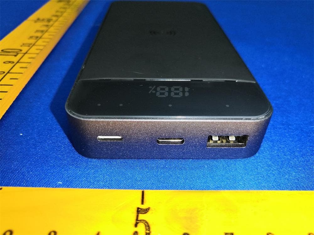
2ATGY-PWB1085SG
Apr 10, 2021Power Bank
Equipment Class
DXX - Part 15 Low Power Communication Device Transmitter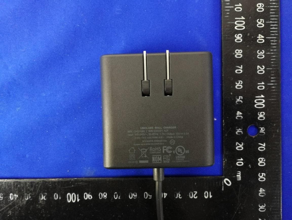
2ATGY-AWC1109
Mar 11, 2021Wireless Charging Stand
Equipment Class
DCD - Part 15 Low Power Transmitter Below 1705 kHz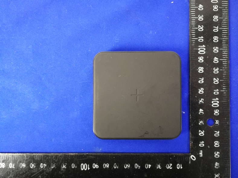
2ATGY-AWC1098
Feb 23, 2021Wireless Charging Pad
Equipment Class
DCD - Part 15 Low Power Transmitter Below 1705 kHz