2ATIH-DR02PDASH CAM
Aukey Technology Co.,Ltd.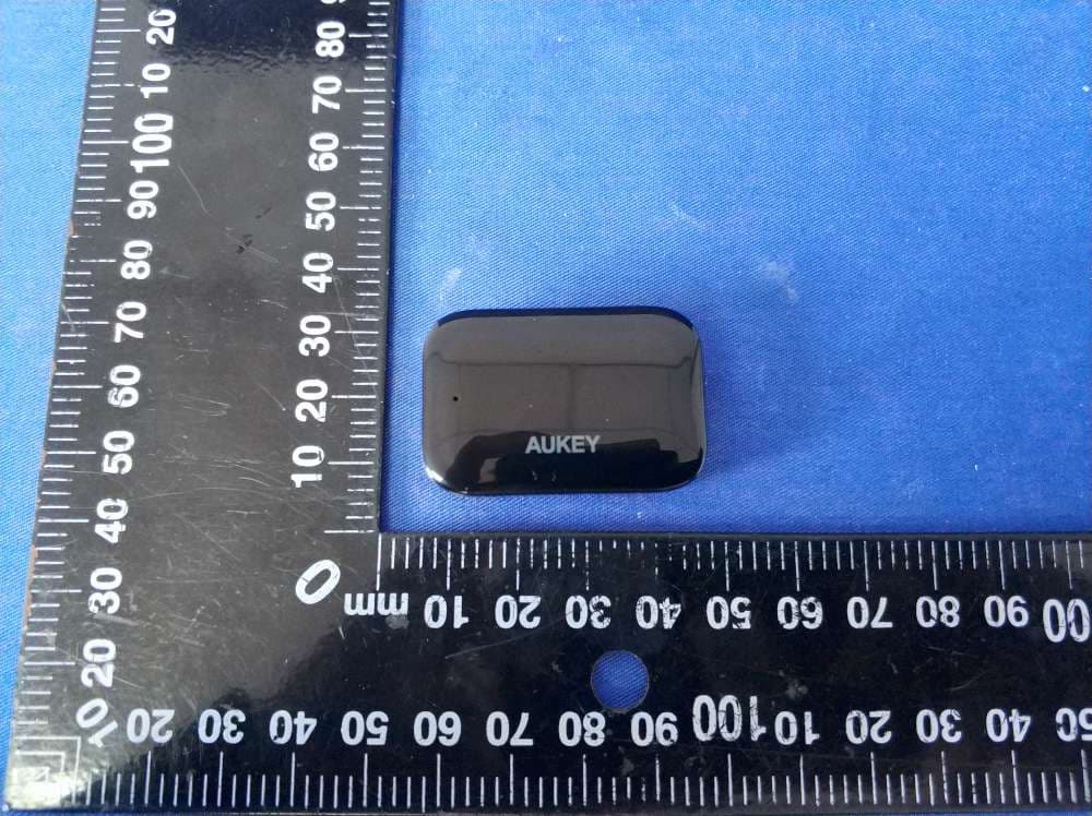
Click to zoom
Application Details
- Equipment Class
- DTS - Digital Transmission System
- Date of Grant
- Apr 08, 2020
- Application Purpose
- Original Equipment
- Date of Application
- Apr 08, 2020
- Equipment Note
- DASH CAM
- Frequency Range
- 2422.00000000 - 2452.00000000
- Company
- Aukey Technology Co.,Ltd.
- Country
- China
Documents & Files
Document Text
Text extracted from the exhibit documents filed with the FCC. Open a document above to read the original.
Users Manual
Settings Tap in the upper-right corner of the app to enter settings. Snapshot Tap to stop recording (the icon will change to ); then tap to take a snapshot. Audio Recording Tap to turn on/off audio recording. Downloading and Viewing Photos and Videos Tap to stop recording (the icon will change to ); then tap to view photos and videos. Tap the photo or video you want to save; then tap to download it to your phone. Alternatively, tap to delete it. Note: Files and settings can’t be accessed while recording is in progress. Video Recording Loop Recording Recording will begin automatically after powering on with a microSD card in the device. Each recorded file is up to ten minutes long, with old footage being replaced when microSD card storage is full. Motion Detection Recording Switch on motion detection in ‘Setup.’ This function will start recording video when the dash camera detects motion in front and stop recording when motion is no longer detected. Time-Lapse Recording Switch on time-lapse recording in ‘Setup.’ This function will capture a picture per second to make a video played at 30fps. Press to delete or to lock/unlock a photo or video file after selecting it from the playlist. If a video is being played, press to stop it and then press to delete or to lock/unlock Once deleted, photos and videos can’t be recovered If you lock a photo or video, it will be protected and not overwritten Hold down for 3 seconds to take a snapshot while in recording mode The snapshot files are located in the \AUKEY\PHOTO folder on the microSD card The icon will be shown after you take a snapshot. This will not interrupt the video recording - 01 - User Manual Screen Control Buttons LED Indicator USB Mini-B Power Input GPS Input Wi-Fi Transmitter Connection Port Mount Locking Clip Lens Microphone Micro SD Card Slot Reset Button Wi-Fi Transmitter Wi-Fi Transmitter Cable Model Image Sensor CPU Screen Wide-Angle Lens Exposure Value Recording Resolutions Recording Modes Sound Recording Gravity Sensor Sensitivity Image Format MicroSD Card Input Operating Temperature Materials DR02 P Sony Exmor IMX323 2.19-megapixel CMOS sensor NT96655 1.5” LCD 170° -1.0, -2/3, -1/3, +0.0, +1/3, +2/3, +1.0 1080p (30fps), 720p (60fps), 720p (30fps), WVGA, VGA Loop, Motion Detection, Time-Lapse, Emergency Recording On / Off Low / Medium / High JPEG Class 10 or higher, 128GB Max DC 5V 1A–2A -30°C – 75°C (-22°F – 167°F) PC, ABS, glass Dash camera: 77 x 51 x 37mm / 3” x 2” x 1.45” Wi-Fi transmitter: 40 x 27 x 11mm / 1.57” x 1.06” x 0.43” - 02 -- 03 -- 04 -- 05 -- 06 -- 07 -- 08 -- 09 -- 09 - Thank you for purchasing the AUKEY DR02 P Wi-Fi Dashboard Camera. Please read this user manual carefully and keep it for future reference. If you need any assistance, please contact our support team with your product model number and Amazon order number. Package Contents Wi-Fi Dashboard Camera Wi-Fi Transmitter Wi-Fi Transmitter Cable Dual-Port USB Car Charger USB Mini-B Cable Sticker Mount Two 3M Stickers Six Cable Clips User Manual Warranty Card Optional Accessory: The AUKEY GM-32 GPS Antenna provides accurate position and speed data to the DR02 P that is saved and displayed on recorded videos. This extended information may support your case in any driving disputes or incidents. Product DiiagramSpecifications Dimensions System LED Indicator Status Solid Green Flashing Green Off Meaning On; not recording On; recording Off Control Buttons ButtonRecording Mode Enter Emergency Recording mode View playlist (short press) Turn on/off Audio Recording (long press) Open Setup menu (short press) Take a snapshot (long press) Turn on/off the screen Playlist & Setup Menu Return to previous menu Enter / Confirm Playback Mode Return to playlist / Stop Play / Pause Reset Button Short press to restart the device (this won’t affect saved files) Move downLock & Unlock / Fast-forward Delete / Rewind Move up Using a MicroSD Card The camera doesn’t include internal storage and requires a microSD card (Class 10+ recommended and 128GB Max supported) to function. A 128GB microSD card should store around 20 hours of 1080p recordings. Use a high-quality, branded card for maximum reliability. Insert a microSD card into the camera microSD card slot. Later, when the camera is powered on, format it (‘Format’ option in Dash Camera ‘Setup’) to prepare the card for first use in the dash camera. Formatting will permanently erase any data on the microSD card. For best performance, format periodically (after backing up any important files). ‘Format Warning’ in ‘Settings’ can be switched on to remind you to do this. Installation & Powering On/Off For optimal performance, install the AUKEY DR02 P in the top-center of your windshield, facing directly ahead. Connect the Wi-Fi transmitter to the dash camera with the Wi-Fi transmitter cable, and fix the transmitter in a suitable position near the dash camera. Use the cable clips to help fix the USB mini-B power cable conveniently and safely like in the picture below. Caution: AUKEY is not responsible for any damage caused to or by the air bag due to incorrect placement of the device or its cable. To power on, insert the car charger into your car’s 12V socket, then connect the power cable to the car charger and to the USB mini-B port of the DR02 P. After powering on each time, the system will start recording automatically. To power off, disconnect the power cable. Using the AukeyOnboard App Download and use the AukeyOnboard dash camera app to download, view, and share your footage, and also to conveniently change camera settings with a smartphone or tablet. Setting Up the App Emergency Recording Manual File Backup Press to back up the current file so that it won’t be overwritten. A icon will appear in the top left of the LCD screen to indicate a protected emergency recording is in progress. Auto File Backup Once the G-sensor is activated by a sudden impact, the device will automatically protect the current recording from being overwritten…
Text truncated - open the document above for the full version.
Cover Letter(s)
CONFIDENTIALITY REQUEST for Certification Service in USA Federal Communication Commission Equipment Authorization Division, Application Processing Branch 7435 Oakland Mills Road Columbia, MD 21046 <2020-04-03> TO WHOM IT MAY CONCERN Pursuant to Paragraphs §0.457 and 0.459 of the Commission’s Rules (47 C.F.R.) and Section §552(b)(4) of the Freedom of Information Act, we requests confidentiality for the following products: FCC ID Model name 2ATIH-DR02PDR02 P For the product stated above, we request that the following information be held confidential; Exhibits Long-Term Confidentiality Short-Term Confidentiality Short-Term Confidentiality Days External Photos Internal Photos Block Diagram Schematics Test Setup Photos User’s Manual Parts List Tune Up Operational Descriptions The long-term confidentiality exhibits contain our trade secrets and proprietary information that could be of benefit to our competitors. The short-term confidentiality on the basis of ensuring that business sensitive information remains confidential until the actual marketing of our new device. If you have any questions, please feel free to contact me at the address shown below. Sincerely, ------------------------------------ Name:Jiaguang Zhou/Manage r Company:Aukey Technology Co., Ltd Address: No.102, Bldg. P09, Electronics Trade Center Huanan City, Pinghu Town, Longgang, Shenzhen, Guangdong, 518111, China Phone:(86) 755-33620645 Fax:(86) 755-33620645 E-Mail:[email protected]
Cover Letter(s)
Aukey Technology Co., Ltd No.102, Bldg. P09, Electronics Trade Center Huanan City, Pinghu Town, Longgang, Shenzhen, Guangdong, 518111, China Tel: (86) 755-33620645 Fax:(86) 755-33620645 Date: Apr. 03 , 2020 FCC ID: 2ATIH-DR02P Model Number: DR02 P, To: Federal Communications Commission Authorization and Evaluation Division 7435 Oakland Mills Road Columbia, MD To Whom It May Concern, We,AukeyTechnologyCo.,Ltd, declare that this EUT (FCC ID:2ATIH-DR02P) doesn’t have Ad Hoc mode function on“non-US/Canada frequencies”. In addition. The frequency selection feature is disabled by firmware for devices marked to the US/Canada. For DTS part of this device, only channels 1-11 will be used in North America, Country code selection is disabled. Should you have any questions or comments regarding this matter, please have Aukey Technology Co., Ltd No.102, Bldg. P09, Electronics Trade Center Huanan City, Pinghu Town, Longgang, Shenzhen, Guangdong, 518111, China Tel: (86) 755-33620645 Fax:(86) 755-33620645 my best attention. Sincerely, Name:Jiaguang Zhou/Manager Company: Aukey Technology Co., Ltd Address: No.102, Bldg. P09, Electronics Trade Center Huanan City, Pinghu Town, Longgang, Shenzhen, Guangdong, 518111, China Phone:(86) 755-33620645 Fax:(86) 755-33620645 E-Mail:[email protected]
Cover Letter(s)
Aukey Technology Co., Ltd No.102, Bldg. P09, Electronics Trade Center Huanan City, Pinghu Town, Longgang, Shenzhen, Guangdong, 518111, China Tel: (86) 755-33620645 Fax:(86) 755-33620645 Federal Communications Commission Authorization and Evaluation Division Equipment Authorization Branch 7435 Oakland Mills Road Columbia, MD 21046 4/6/20 To whom it may concern: We, the undersigned, hereby authorize Eurofins Product Service GmbH to act on our behalf in all matters relating to applications for equipment authorization FCC ID:[ 2ATIH-DR02P ]including the signing of all documents related to these matters. Any and all acts carried out by Eurofins Product Service GmbH on our behalf shall have the same effect as acts of our own. We also hereby certify that no party to this application is subject to a denial of benefits, including FCC benefits, pursuant to Section 5301 of the Anti-Drug Abuse Act of 1988, 21 U.S.C. 862. Sincerely, Name:Jiaguang Zhou/Manager Company: Aukey Technology Co., Ltd Address: No.102, Bldg. P09, Electronics Trade Center Huanan City, Pinghu Town, Longgang, Shenzhen, Guangdong, 518111, China Phone:(86) 755-33620645 Fax:(86) 755-33620645 E-Mail:[email protected]
External Photos
Parts EUT
ID Label/Location Info
10.5 mm FCC ID: 2ATIH-DR02P FCC ID: 2ATIH-DR02P
Internal Photos
Ant
RF Exposure Info
FCC ID:2ATIH-DR02P 1. M e t h o d o f m e a s u r e m e n t 1.1. Applicable Standard According to §1.1307(b)(1), systems operating under the provisions of this section shall be operated in a manner that ensures that the public is not exposed to radio frequency energy level in excess of the Commission’s guidelines. According to §1.1310 and §2.1091 RF exposure requirement KDB447498 v06: Mobile and Portable Devices RF Exposure Procedures and Equipment Authorization Policies. 1.2. Requirement According to KDB447498 D01 General RF Exposure Guidance v06 Section 4.3.1 Standalone SAR test exclusion considerations: “Unless specifically required by the published RF exposure KDB procedures, standalone 1-g head or body and 10-g extremity SAR evaluation for general population exposure conditions, by measurement or numerical simulation, is not required when the corresponding SAR Test Exclusion Threshold condition, listed below, is satisfied. These test exclusion conditions are based on source-based time-averaged maximum conducted output power of the RF channel requiring evaluation, adjusted for tune-up tolerance, and the minimum test separation distance required for the exposure conditions.22 The minimum test separation distance is determined by the smallest distance from the antenna and radiating structures or outer surface of the device, according to the host form factor, exposure conditions and platform requirements, to any part of the body or extremity of a user or bystander (see 5) of section 4.1). To qualify for SAR test exclusion, the test separation distances applied must be fully explained and justified by the operating configurations and exposure conditions of the transmitter and applicable host platform requirements, typically in the SAR measurement or SAR analysis report, according to the required published RF exposure KDB procedures. When no other RF exposure testing or reporting is required, a statement of justification and compliance must be included in the equipment approval, in lieu of the SAR report, to qualify for the SAR test exclusion. When required, the device specific conditions described in the other published RF exposure KDB procedures must be satisfied before applying these SAR test exclusion provisions; for example, handheld PTT two-way radios, handsets, laptops & tablets etc.23 “ [(max. power of channel, including tune-up tolerance, mW)/ (min. test separation distance, mm)] · [√f (GHz)] ≤ 3.0 for 1-g SAR and ≤ 7.5 for 10-g extremity SAR, where: • f (GHz) is the RF channel transmit frequency in GHz • Power and distance are rounded to the nearest mW and mm before calculation • The result is rounded to one decimal place for comparison • 3.0 and 7.5 are referred to as the numeric thresholds in the step 2 below The test exclusions are applicable only when the minimum test separation distance is ≤ 50 mm and for transmission frequencies between 100 MHz and 6 GHz. When the minimum test separation distance is < 5 mm, a distance of 5 mm according to 5) in section 4.1 is applied to determine SAR test exclusion. Report No.: UNIA20032003-1FR Page 2 of 3 1.3. Limit Limits for Maximum Permissible Exposure (MPE)/Controlled Exposure Frequency Range(MHz) Electric Field Strength(V/m) Magnetic Field Strength(A/m) Power Density (mW/cm²) Averaging Time (minute) Limits for Occupational/Controlled Exposure 0.3 – 3.0 3.0 – 30 30 – 300 300 – 1500 1500 – 100,000 614 1842/f 61.4 / / 1.63 4.89/f 0.163 / / (100) * (900/f 2 )* 1.0 f/300 5 6 6 6 6 6 Limits for Maximum Permissible Exposure (MPE)/Uncontrolled Exposure Frequency Range(MHz) Electric Field Strength(V/m) Magnetic Field Strength(A/m) Power Density (mW/cm²) Averaging Time (minute) Limits for Occupational/Controlled Exposure 0.3 – 3.0 3.0 – 30 30 – 300 300 – 1500 1500 – 100,000 614 824/f 27.5 / / 1.63 2.19/f 0.073 / / (100) * (180/f 2 )* 0.2 f/1500 1.0 30 30 30 30 30 F=frequency in MHz *=Plane-wave equivalent power density 1.4. MPE Calculation Method Predication of MPE limit at a given distance Equation from page 18 of OET Bulletin 65, Edition 97-01 S=PG/4πR² Where: S=power density P=power input to antenna G=power gain of the antenna in the direction of interest relative to an isotropic radiator R=distance to the center of radiation of the antenna As declared by the Applicant, the EUT transmits with the maximum soure-baed Duty Cycle of 100%-see the User manual, and the EUT is a wireless device used in a mobile application, at least 20 cm from any body part of the user or nearby persons; from the maximum EUT RF output power, the minimum mobile separation distance, r =20cm, as well as the gain of the used antenna is 1.06dBi for WLAN, and the power drift from Turn-up Procedure provide by manufacturer as following states, the RF power density can be obtained.. Report No.: UNIA20032003-1FR Page 3 of 3 1.5. Antenna Information only use antennas certificated as follows provided by manufacturer; Antenna Identification in Internal photos Antenna type and antenna number Operate frequency band Maximum antenna gain 2.4G Wifi Internal Antenna 2.412GHz – 2.462 GHz 2.43 dBi Evaluation Results for Standalone Modulati on Type Target power W/ tolerance (dBm) Max tune up power tolerance(dB m) Max Output power to antenna (mW) Antenna Gain (Numeric) Power Density at R=20cm (mW/cm2) Limit (mW/cm2) Result 802.11b 11±1.0 12 15.849 2.43 0.00552 1.0 Pass 802.11g 10±1.0 11 12.589 2.43 0.00438 1.0 Pass 802.11n (HT20) 10±1.0 11 12.589 2.43 0.00438 1.0 Pass 802.11n (HT40) 9±1.0 10 10.000 2.43 0.00348 1.0 Pass 2. C o n c l u s i o n The measurement results comply with the FCC Limit per 47 CFR 2.1091 for the uncontrolled RF Exposure of mobile device. .....................End of Report.........................
Test Report
Page 1 of 52 Report No.: UNIA20032003FR-01 FCC RADIO TEST REPORT FCC ID: 2ATIH-DR02P Product: DASH CAM Trade Name: AUKEY Model Name: DR02 P Serial Model: DR01 P, DRA1 P Report No.: UNIA20032003FR-01 Prepared for Aukey Technology Co., Ltd Room 102, Building P09, South China City Electronic trading center, Longgang District, Shenzhen Prepared by Shenzhen United Testing Technology Co., Ltd. 2F, Annex Bldg, Jiahuangyuan Tech Park, #365 Baotian 1 Rd, Tiegang Community, Xixiang Str, Bao'an District, Shenzhen, China Page 2 of 52 Report No.: UNIA20032003FR-01 TEST RESULT CERTIFICATION Applicant’s name .................... : Aukey Technology Co., Ltd Address ...................................... : Room 102, Building P09, South China City Electronic trading center, Longgang District,Shenzhen Manufacture's Name .............. : Aukey Technology Co.,Ltd Address ...................................... : Room 102, Building P09, South China City Electronic trading center, Longgang District,Shenzhen Product description Product name ............................... : DASH CAM Trade Mark ................................. : AUKEY Model and/or type reference . : DR02 P, DR01 P, DRA1 P Standards .................................. : FCC Rules and Regulations Part 15 Subpart C Section 15.247 ANSI C63.10: 2013 This device described above has been tested by Shenzhen United Testing Technology Co., Ltd., and the test results show that the equipment under test (EUT) is in compliance with the FCC requirements. And it is applicableonly to the tested sample identified in the report. This report shall not be reproduced except infull, without the written approval of UNI, this document may be altered or revised by Shenzhen United Testing Technology Co., Ltd., personnel only, and shall be noted in the revision of the document. Date of Test ............................................... : Date (s) of performance of tests ............... : Mar. 18 ~ Mar. 30, 2020 Date of Issue..............................................: Apr. 02, 2020 Test Result .................................................. :Pass Prepared by: Kahn yang/Editor Reviewer: Sherwin Qian/Supervisor Approved & Authorized Signer: Liuze/Manager Page 3 of 52 Report No.: UNIA20032003FR-01 Table of ContentsPage 1. TEST SUMMARY ................................................................................................................... 5 2. GENERAL INFORMATION...................................................................................................6 2.1 GENERAL DESCRIPTION OF EUT ......................................................................................... 6 2.2 Carrier Frequency of Channels ................................................................................................. 7 2.3 Operation of EUT during testing ................................................................................................ 7 2.4 DESCRIPTION OF TEST SETUP ............................................................................................. 7 2.5 MEASUREMENT INSTRUMENTS LIST .................................................................................. 8 3. CONDUCTED EMISSIONS TEST .................................................................................... 9 3.1 Conducted Power Line Emission Limit.....................................................................................9 3.2 Test Setup.....................................................................................................................................9 3.3 Test Procedure.............................................................................................................................9 3.4 Test Result....................................................................................................................................9 4. RADIATED EMISSION TEST ............................................................................................. 10 4.1 Radiation Limit ........................................................................................................................... 10 4.2 Test Setup ................................................................................................................................... 10 4.3 Test Procedure ........................................................................................................................... 11 4.4 Test Result ................................................................................................................................... 11 5. BAND EDGE.........................................................................................................................26 5.1 Limits ........................................................................................................................................... 26 5.2 Test Procedure ........................................................................................................................... 26 5.3 Test Result .................................................................................................................................. 26 6. OCCUPIED BANDWIDTH MEASUREMENT .................................................................. 29 6.1 Test Limit.....................................................................................................................................29 6.2 Test Procedure...........................................................................................................................29 6.3 Measurement Equipment Used...............................................................................................29 6.4 Test Result..................................................................................................................................29 7. POWER SPECTRAL DENSITY TEST .............................................................................. 36 7.1 Test Limit ........................................…
Text truncated - open the document above for the full version.
Test Setup Photos
Radiated Emission (Below 1G) Radiated Emission (Above 1G)
Contact Information
Applicant
Jiaguang Zhou(Manager)
Test Firm
Shenzhen United Testing Technology Co., Ltd.Liu Ze
[email protected]86-755-86180996
Technical Specifications
| # | Rule Parts | Frequency Range | Power Output |
|---|---|---|---|
| 2 | 15C | 2.42 GHz - 2.45 GHz | 9.00 mW |
Other Applications from Aukey Technology Co.,Ltd.
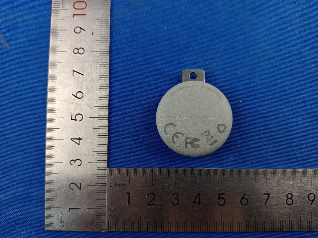
2ATIH-TM-10
Sep 07, 2024Smart Bluetooth Tracker
Equipment Class
DTS - Digital Transmission System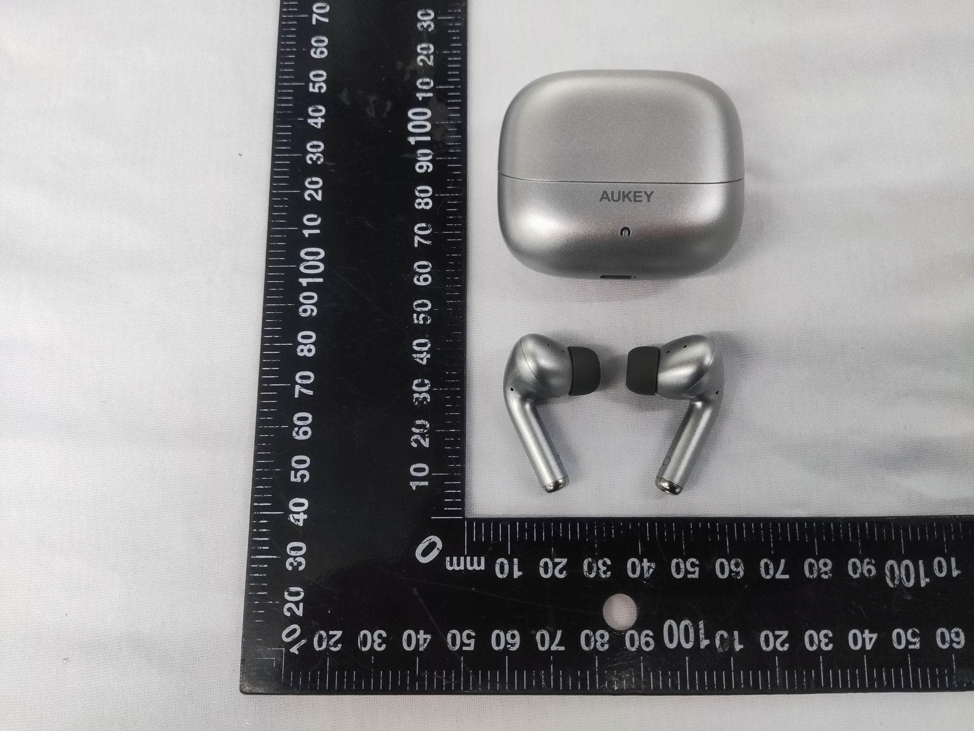
2ATIH-EP-B1
Aug 15, 2024True Wireless Earbuds with Hybrid ANC
Equipment Class
DSS - Part 15 Spread Spectrum Transmitter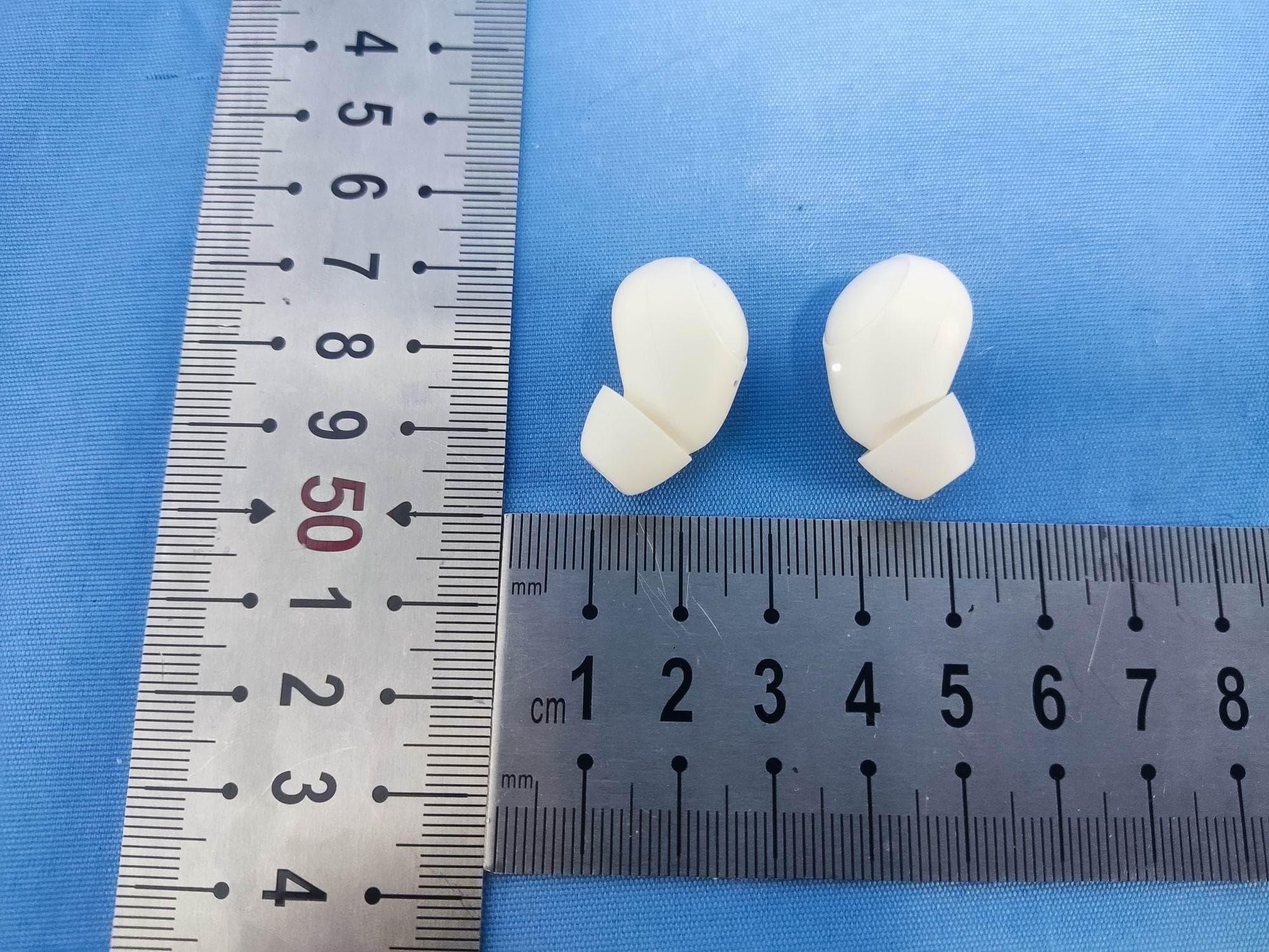
2ATIH-EP-M3A
Jul 30, 2024True Wireless Earbuds
Equipment Class
DSS - Part 15 Spread Spectrum Transmitter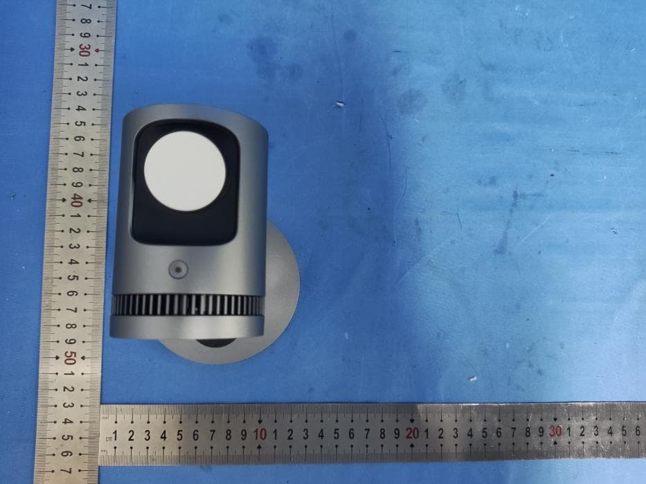
2ATIH-LC-MC311A
Jul 21, 2024MagFusion 3-in-1 Pro Qi2 Magnetic Fast Wireless Charging Station with Active Cooling System
Equipment Class
DCD - Part 15 Low Power Transmitter Below 1705 kHz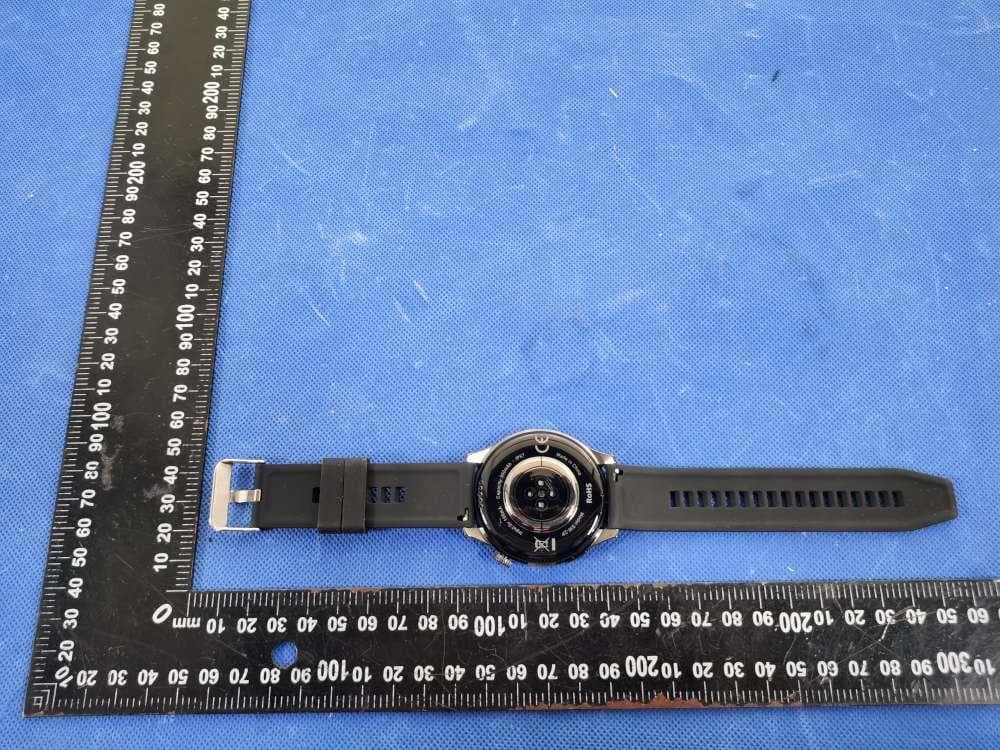
2ATIH-SW2P
Dec 09, 2023SmartWatch
Equipment Class
DXX - Part 15 Low Power Communication Device Transmitter