2ATIH-EP-N5Bluetooth Wireless Earbuds
Aukey Technology Co.,Ltd.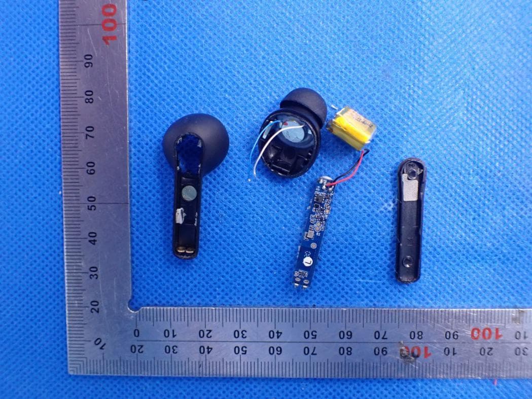
Click to zoom
Application Details
- Equipment Class
- DSS - Part 15 Spread Spectrum Transmitter
- Date of Grant
- Nov 17, 2020
- Application Purpose
- Original Equipment
- Date of Application
- Nov 17, 2020
- Equipment Note
- Bluetooth Wireless Earbuds
- Frequency Range
- 2402.00000000 - 2480.00000000
- Company
- Aukey Technology Co.,Ltd.
- Country
- China
Documents & Files
Document Text
Text extracted from the exhibit documents filed with the FCC. Open a document above to read the original.
Users Manual
材质:105g 铜版纸 尺寸:85*85mm 风琴折页(双面印刷) 印刷颜色:单黑 封面背面留白 - 01 - English Deutsch Français Español Italiano 01~11 12~21 22~31 32~41 42~51 52~60 Contents User Manual Wireless Earbuds Model: EP-N5 - 02 -- 03 -- 04 -- 05 -- 06 -- 07 -- 08 -- 09 -- 10 - Thank you for purchasing the AUKEY EP-N5 True Wireless Earbuds. Please read this user manual carefully and keep it for future reference. If you need any assistance, please contact our support team with your product model number and Amazon order number. Package Contents True Wireless Earbuds Charging Case Three Pairs of Ear-Tips (S/M/L) USB-A to C Cable Quick Start Guide User Manual Warranty Card Product Diagram Getting Started Charging Fully charge the charging case before first use. Connect the charging case to a USB charger or charging port with the included USB-A to C cable. When all 4 LED charging indicator lights are green, the case is fully charged. Charging takes around 2 hours, and after being fully charged, the case can fully charge the earbuds 4 times. The earbuds should be stored in the case when not in use. When the earbuds are charging in the case (with the case itself not charging), the LED indicators on the earbuds will turn solid red. When the indicators turn off, the earbuds are fully charged. USB-C Charging Input Charging Pins LED Charging Indicator Touch-Sensitive Panel Microphone LED Status Indicator Specifications Earbuds Charging Case Model Technology Driver (each channel) Sensitivity Frequency Range Impedance Microphone Type Microphone Sensitivity Microphone Frequency Range Charg ing Time Battery Life Battery Type Operating Range Weight EP-N5 BT 5, A2DP, HFP, HSP, AVRCP 1 x 10mm / 0.3” speaker driver 101dB ±3dB 20Hz – 20kHz 32 ohm MEMS mic (microphone chip) -42dB ±1dB 200Hz – 5kHz 1.5 hours Up to 7 hours Li-polymer (2 x 60mAh) Up to 10m / 33ft 10g / 0.35oz Charging Input Charging Time Battery Type Number of Earbuds Recharges Weight DC 5V 2 hours Li-polymer (500mAh) 4 times (pair) 37.8g / 1.33oz Turning On / Off Turn On Turn Off Open the lid of the charging case Put the earbuds back in the charging case and close the lid Pairing Starting with the earbuds in the case: Using the Left/Right Earbud Only Starting with the earbuds in the case: Regular Use After Pairing Once the earbuds are successfully paired with your device, they can be switched on and off as follows: Open the lid of the charging case. Both earbuds will turn on automatically and connect with each other Turn on the pairing function on the device you want to pair with the earbuds From the list of available devices, find and select “AUKEY EP-N 5” If a code or PIN is required for pairing, enter “0000” Active Noise Canceling Active noise canceling functionality requires the use of both earbuds. 1. 2. 3. 4. Clearing the Pairing List Make sure both earbuds are off and in the charging case. Take one of the earbuds out Tap the touch-sensitive panel 5 times, and then the earbud will enter pairing mode (note: keep one earbud in the charging case, and the lid is closed, when you operate the other one) Tap the touch-sensitive panel 7 times to clear the previous pairing list, and the earbud will turn off Take the other earbud out of the charging case and repeat the previous steps 2 & 3 After that, put both earbuds back in the charging case and close the lid. Open the lid again, and both earbuds will turn on automatically and are ready to pair 1. 2. 3. 4. 5. Löschen der Pairing-Liste Stellen Sie sicher, dass sich beide Ohrhörer ausgeschaltet im Lade-Case befinden. Nehmen Sie einen der Ohrhörer heraus. Tippen Sie 5-mal auf das berührungssensitive Bedienfeld. Der Ohrhörer wechselt daraufhin in den Pairing-Modus. (Hinweis: Bewahren Sie einen Kopfhörer im Ladekoffer auf, und der Deckel ist geschlossen, wenn Sie den anderen bedienen.) Tippen Sie 7-mal auf das berührungssensitive Bedienfeld, um die aktuelle Pairing-Liste zu löschen. Der Ohrhörer schaltet sich daraufhin aus. Nehmen Sie den anderen Ohrhörer aus dem Lade-Case und wiederholen Sie die Schritte 2 und 3. Setzen Sie anschließend beide Ohrhörer wieder in das Lade-Case ein und schließen Sie den Deckel. Öffnen Sie den Deckel erneut. Beide Ohrhörer schalten sich automatisch ein und sind bereit zum Koppeln. 1. 2. 3. 4. 5. Effacer la liste de jumelage Assurez-vous que les deux écouteurs sont éteints et dans le boîtier de charge. Retirez l’un des écouteurs Appuyez 5 fois sur le panneau tactile, puis l’écouteur entrera en mode couplage. (Remarque: gardez un écouteur dans l'étui de chargement et le couvercle est fermé lorsque vous utilisez l'autre) Appuyez 7 fois sur le panneau tactile pour effacer la liste de couplage précéden- te et l’écouteur s’éteindra Retirez l’autre écouteur du boîtier de charge et répétez les étapes 2 et 3 précédentes Après cela, remettez les deux écouteurs dans l’étui de charge et fermez le couvercle. Ouvrez à nouveau le couvercle et les deux écouteurs s’allumeront automatiquement et seront prêts à être couplés 1. 2. 3. 4. 5. Borrar la lista de emparejamiento Asegúrate de que ambos auriculares están apagados y en el estuche de carga. Saca uno de los auriculares. Toca el panel táctil 5 veces, y luego el auricular activará el modo de emparejamiento. (nota: mantenga un auricular en el estuche de carga y la tapa esté cerrada cuando opere el otro) Toca el panel táctil 7 veces para borrar la lista de emparejamiento anterior, y el auricular se apagará. Saca el otro auricular del estuche de carga y repite los pasos anteriores 2 y 3. Después de eso, vuelve a colocar ambos auriculares en el estuche de carga y cierra la tapa. Vuelve a abrir la tapa y ambos auriculares se encenderán automáticamente y estarán listos para emparejarse 1. 2. 3. 4. 5. Cancellazione dell'elenco degli accoppiamenti Assicurarsi che entrambi gli auricolari siano spenti e nella custodia di ricarica. Togliere uno degli auricolari. Toccare il pannello sensibile al tatto 5 volte e l'auricolare entrerà in modalità accoppiamento. (nota: tieni un auricolare …
Text truncated - open the document above for the full version.
Cover Letter(s)
Aukey Technology Co.,Ltd. Room 102, Building P09, South China City Electronic trading center, Longgang District, Shenzhen, China Agent Authorization Company: Aukey Technology Co.,Ltd. Address: Room 102, Building P09, South China City Electronic trading center, Longgang District, Shenzhen, China Product Name: Wireless Earbuds Model Number(s): EP-N5 Product Description: Bluetooth Wireless Earbuds We authorize MiCOM Labs Inc., 575 Boulder Court, Pleasanton, California 94566, USA, to act on our behalf on all matters concerning the certification of above named equipment. We declare that MiCOM Labs Inc. is allowed to forward all information related to the approval and certification of equipment to the regulatory agencies as required and to discuss any issues concerning the approval application. Any and all acts carried out by MiCOM Labs on our behalf shall have the same effect as acts of our own. Signature: Date: Aug. 13, 2020 Name: Jiaguang Zhou Title: General Manager Company: Aukey Technology Co.,Ltd.
ID Label/Location Info
FCC ID and TELEC Label Location Page 1 and 9 from the User Manual
Internal Photos
Internal Photos Left OPEN VIEW OF EUT VIEW OF BATTERY INTERNAL VIEW OF EUT-1 INTERNAL VIEW OF EUT-2 BT Antenna INTERNAL VIEW OF EUT-3 INTERNAL VIEW OF EUT-4 Right OPEN VIEW OF EUT VIEW OF BATTERY INTERNAL VIEW OF EUT-1 INTERNAL VIEW OF EUT-2 BT Antenna INTERNAL VIEW OF EUT-3 INTERNAL VIEW OF EUT-4 Charging Dock OPEN VIEW OF EUT VIEW OF BATTERY INTERNAL VIEW OF EUT-1 INTERNAL VIEW OF EUT-2
RF Exposure Info
RF EXPOSURE EVALUATION 1. PRODUCT INFORMATION Product Description Wireless Earbuds Model Name EP-N5 FCC ID 2ATIH-EP-N5 2. EVALUATION METHOD According to 447498 D01 General RF Exposure Guidance v05 The 1-g and 10-g SAR test exclusion thresholds for 100 MHz to 6 GHz at test separation distances ≤ 50 mm are determined by: [(max. power of channel, including tune-up tolerance, mW)/(min. test separation distance, mm)] ·[√f(GHz)] ≤ 3.0 for 1-g SAR and ≤ 7.5 for 10-g extremity SAR. Where f(GHz) is the RF channel transmit frequency in GHz Power and distance are rounded to the nearest mW and mm before calculation 3. CALCULATION P t =4.608dBm=2.89mW The value of the Maximum output power P t is referred to the test report of the CFR47 §15.247. The result for RF exposure evaluation SAR=(2.89mW /5mm) .[√2.480(GHz)]=0.91<3.0 for 1-g SAR and ≤ 7.5 for 10-g extremity SAR. 4. CONCLUSION The SAR evaluation is not required.
Test Report
Page 1 of 79 FCC Test Report Report No.: AGC08574200601FE03 FCC ID : 2ATIH-EP-N5 APPLICATION PURPOSE : Original Equipment PRODUCT DESIGNATION : Wireless Earbuds BRAND NAME : AUKEY MODEL NAME : EP-N5 APPLICANT : Aukey Technology Co., Ltd. DATE OF ISSUE : Aug. 12, 2020 STANDARD(S) : FCC Part 15.247 REPORT VERSION : V1.0 Attestation of Global Compliance (Shenzhen) Co., Ltd Report No.: AGC08574200601FE03 Page 2 of 79 REPORT REVISE RECORD Report Version Revise Time Issued Date Valid Version Notes V1.0 / Aug. 12, 2020 Valid Initial Release Report No.: AGC08574200601FE03 Page 3 of 79 TABLE OF CONTENTS 1. VERIFICATION OF CONFORMITY .................................................................................................................. 5 2. GENERAL INFORMATION .............................................................................................................................. 6 2.1. PRODUCT DESCRIPTION ........................................................................................................................ 6 2.2. TABLE OF CARRIER FREQUENCYS ....................................................................................................... 6 2.3. RECEIVER INPUT BANDWIDTH .............................................................................................................. 7 2.4. EXAMPLE OF A HOPPING SEQUENCY IN DATA MODE ......................................................................... 7 2.5. EQUALLY AVERAGE USE OF FREQUENCIES AND BEHAVIOUR ......................................................... 7 2.6. RELATED SUBMITTAL(S) / GRANT (S) .................................................................................................... 8 2.7. TEST METHODOLOGY ............................................................................................................................. 8 2.8. SPECIAL ACCESSORIES ......................................................................................................................... 8 2.9. EQUIPMENT MODIFICATIONS ................................................................................................................. 8 2.10. ANTENNA REQUIREMENT .................................................................................................................... 8 3. MEASUREMENT UNCERTAINTY ................................................................................................................... 9 4. DESCRIPTION OF TEST MODES ................................................................................................................. 10 5. SYSTEM TEST CONFIGURATION ................................................................................................................. 11 5.1. CONFIGURATION OF EUT SYSTEM ....................................................................................................... 11 5.2 EQUIPMENT USED IN TESTED SYSTEM ................................................................................................ 11 5.3. SUMMARY OF TEST RESULTS ............................................................................................................... 11 2.THE EUT IS POWERED BY BATTERY.6. TEST FACILITY ............................................................................ 11 7. PEAK OUTPUT POWER ................................................................................................................................ 13 7.1. MEASUREMENT PROCEDURE ............................................................................................................. 13 7.2. TEST SET-UP (BLOCK DIAGRAM OF CONFIGURATION) .................................................................... 13 7.3. LIMITS AND MEASUREMENT RESULT .................................................................................................. 14 8. 20DB BANDWIDTH ........................................................................................................................................ 20 8.1. MEASUREMENT PROCEDURE ............................................................................................................. 20 8.2. TEST SET-UP (BLOCK DIAGRAM OF CONFIGURATION) .................................................................... 20 8.3. LIMITS AND MEASUREMENT RESULTS ............................................................................................... 20 9. CONDUCTED SPURIOUS EMISSION........................................................................................................... 27 9.1. MEASUREMENT PROCEDURE ............................................................................................................. 27 9.2. TEST SET-UP (BLOCK DIAGRAM OF CONFIGURATION) .................................................................... 27 9.3. MEASUREMENT EQUIPMENT USED .................................................................................................... 27 9.4. LIMITS AND MEASUREMENT RESULT .................................................................................................. 27 10. RADIATED EMISSION ................................................................................................................................. 40 10.1. MEASUREMENT PROCEDURE ........................................................................................................... 40 10.2. TEST SETUP ......................................................................................................................................... 42 10.3. LIMITS AND MEASUREMENT RESULT ............................................................................................... 43 10.4. TEST RESULT........................................................................................................................................ 43 11.1. MEASUREMENT PROCEDURE............................................................................................................ 53 11.2. TEST SETUP (BLOCK DIAGRAM OF CONFIGURATION)…
Text truncated - open the document above for the full version.
Test Report
Report No.: AGC08574200601FE03 Page 63 of 79 APPENDIX B: PHOTOGRAPHS OF EUT WHOLE VIEW OF EUT TOP VIEW OF EUT Report No.: AGC08574200601FE03 Page 64 of 79 BOTTOM VIEW OF EUT FRONT VIEW OF EUT Report No.: AGC08574200601FE03 Page 65 of 79 BACK VIEW OF EUT LEFT VIEW OF EUT Report No.: AGC08574200601FE03 Page 66 of 79 RIGHT VIEW OF EUT Left VIEW OF EUT(PORT) Report No.: AGC08574200601FE03 Page 67 of 79 OPEN VIEW OF EUT VIEW OF BATTERY Report No.: AGC08574200601FE03 Page 68 of 79 INTERNAL VIEW OF EUT-1 INTERNAL VIEW OF EUT-2 BT Antenna Report No.: AGC08574200601FE03 Page 69 of 79 INTERNAL VIEW OF EUT-3 INTERNAL VIEW OF EUT-4 Report No.: AGC08574200601FE03 Page 70 of 79 Right VIEW OF EUT(PORT) OPEN VIEW OF EUT Report No.: AGC08574200601FE03 Page 71 of 79 VIEW OF BATTERY INTERNAL VIEW OF EUT-1 BT Antenna Report No.: AGC08574200601FE03 Page 72 of 79 INTERNAL VIEW OF EUT-2 INTERNAL VIEW OF EUT-3 Report No.: AGC08574200601FE03 Page 73 of 79 INTERNAL VIEW OF EUT-4 Charging Dock TOP VIEW OF EUT Report No.: AGC08574200601FE03 Page 74 of 79 BOTTOM VIEW OF EUT FRONT VIEW OF EUT Report No.: AGC08574200601FE03 Page 75 of 79 BACK VIEW OF EUT LEFT VIEW OF EUT Report No.: AGC08574200601FE03 Page 76 of 79 RIGHT VIEW OF EUT VIEW OF EUT(port)-1 Report No.: AGC08574200601FE03 Page 77 of 79 VIEW OF EUT(port)-2 OPEN VIEW OF EUT Report No.: AGC08574200601FE03 Page 78 of 79 VIEW OF BATTERY INTERNAL VIEW OF EUT-1 Report No.: AGC08574200601FE03 Page 79 of 79 INTERNAL VIEW OF EUT-2 ----END OF REPORT---- Conditions of Issuance of Test Reports 1. All samples and goods are accepted by the Attestation of Global Compliance (Shenzhen) Co., Ltd (the “Company”) solely for testing and reporting in accordance with the following terms and conditions. The company provides its services on the basis that such terms and conditions constitute express agreement between the company and any person, firm or company requesting its services (the “Clients”). 2. Any report issued by Company as a result of this application for testing services (the “Report”) shall be issued in confidence to the Clients and the Report will be strictly treated as such by the Company. It may not be reproduced either in its entirety or in part and it may not be used for advertising or other unauthorized purposes without the written consent of the Company. The Clients to whom the Report is issued may, however, show or send it, or a certified copy thereof prepared by the Company to its customer, supplier or other persons directly concerned. The Company will not, without the consent of the Clients, enter into any discussion or correspondence with any third party concerning the contents of the Report, unless required by the relevant governmental authorities, laws or court orders. 3.The Company shall not be called or be liable to be called to give evidence or testimony on the Report in a court of law without its prior written consent, unless required by the relevant governmental authorities, laws or court orders. 4. The non-CMA report issued by AGC is only permitted to be used by the client as internal reference use and shall not be used for public demonstration purpose. 5. In the event of the improper use of the report as determined by the Company, the Company reserves the right to withdraw it, and to adopt any other additional remedies which may be appropriate. 6. Samples submitted for testing are accepted on the understanding that the Report issued cannot form the basis of, or be the instrument for, any legal action against the Company. 7. The Company will not be liable for or accept responsibility for any loss or damage however arising from the use of information contained in any of its Reports or in any communication whatsoever about its said tests or investigations. 8.Clients wishing to use the Report in court proceedings or arbitration shall inform the Company to that effect prior to submitting the sample for testing. 9. The Company is not responsible for recalling the electronic version of the original report when any revision is made to them. The Client assumes the responsibility to providing the revised version to any interested party who uses them. 10. Subject to the variable length of retention time for test data and report stored hereinto as otherwise specifically required by individual accreditation authorities, the Company will only keep the supporting test data and information of the test report for a period of six years. The data and information will be disposed of after the aforementioned retention period has elapsed. Under no circumstances shall we provide any data and information which has been disposed of after retention period. Under no circumstances shall we be liable for damage of any kind, including (but not limited to) compensatory damages, lost profits, lost data, or any form of special, incidental, indirect, consequential or punitive damages of any kind, whether based on breach of contract of warranty, tort (including negligence), product liability or otherwise, even if we are informed in advance of the possibility of such damages.
Test Setup Photos
Test Setup Photos RADIATED EMISSION TEST SETUP BELOW 1GHZ RADIATED EMISSION TEST SETUP ABOVE 1GHZ CONDUCTED TEST SETUP
Contact Information
Applicant
Jiaguang Zhou(Manager)
Technical Contact
Test Firm
Attestation of Global Compliance (Shenzhen) Co., LDoris Li
[email protected]+86-755-25234088
Technical Specifications
| # | Rule Parts | Frequency Range | Power Output |
|---|---|---|---|
| 1 | 15C | 2.40 GHz - 2.48 GHz | 2.90 mW |
Other Applications from Aukey Technology Co.,Ltd.
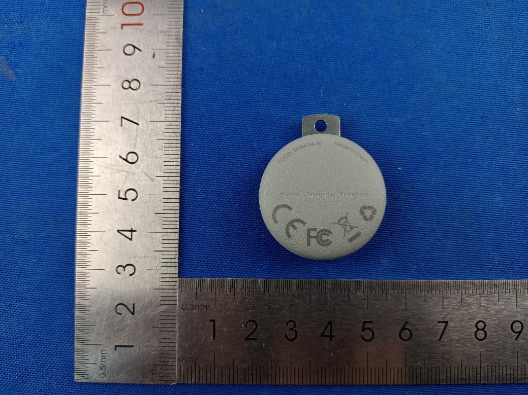
2ATIH-TM-10
Sep 07, 2024Smart Bluetooth Tracker
Equipment Class
DTS - Digital Transmission System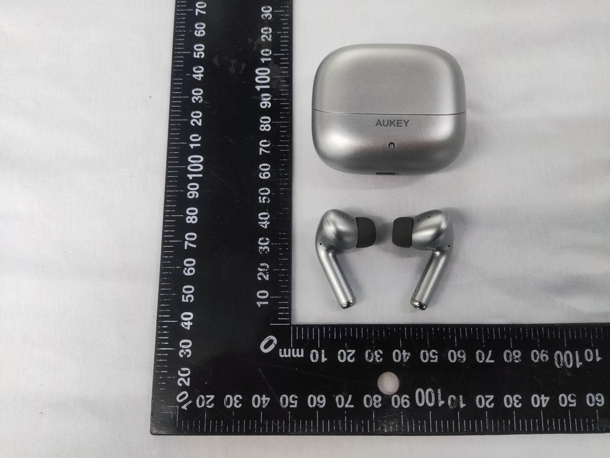
2ATIH-EP-B1
Aug 15, 2024True Wireless Earbuds with Hybrid ANC
Equipment Class
DSS - Part 15 Spread Spectrum Transmitter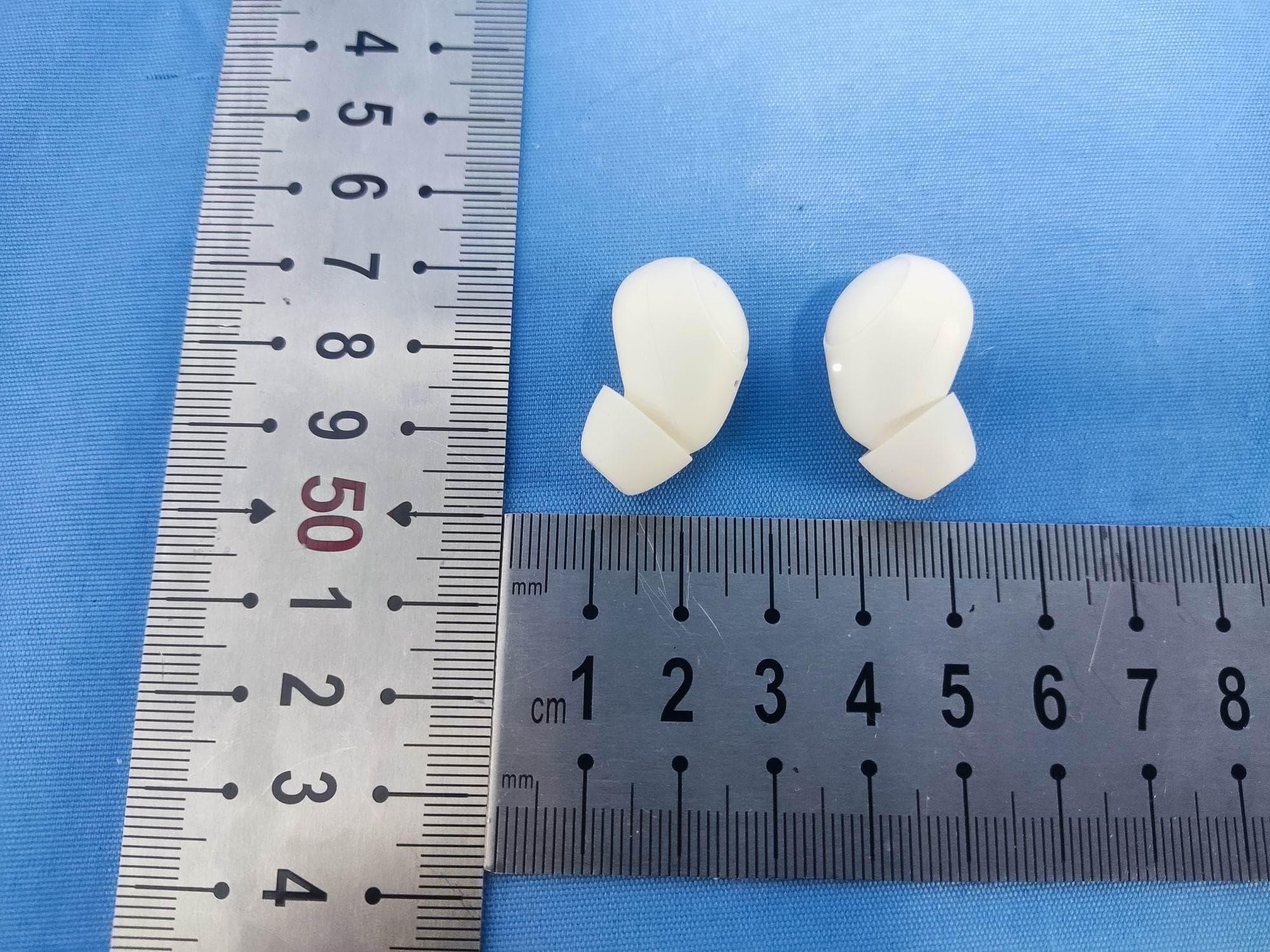
2ATIH-EP-M3A
Jul 30, 2024True Wireless Earbuds
Equipment Class
DSS - Part 15 Spread Spectrum Transmitter
2ATIH-LC-MC311A
Jul 21, 2024MagFusion 3-in-1 Pro Qi2 Magnetic Fast Wireless Charging Station with Active Cooling System
Equipment Class
DCD - Part 15 Low Power Transmitter Below 1705 kHz
2ATIH-SW2P
Dec 09, 2023SmartWatch
Equipment Class
DXX - Part 15 Low Power Communication Device Transmitter