2ATIH-EPT25Wireless Earbuds
Aukey Technology Co.,Ltd.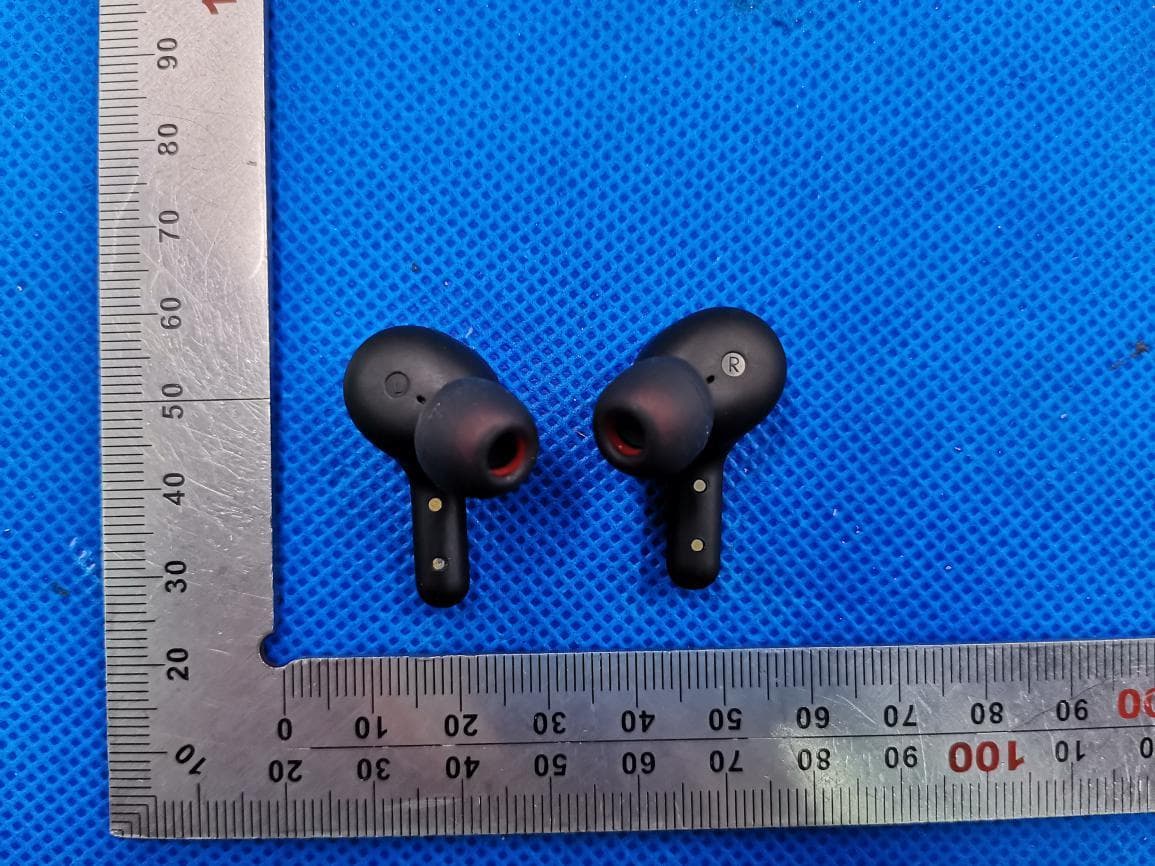
Click to zoom
Application Details
- Equipment Class
- DSS - Part 15 Spread Spectrum Transmitter
- Date of Grant
- Aug 16, 2020
- Application Purpose
- Original Equipment
- Date of Application
- Aug 16, 2020
- Equipment Note
- Wireless Earbuds
- Frequency Range
- 2402.00000000 - 2480.00000000
- Company
- Aukey Technology Co.,Ltd.
- Country
- China
Documents & Files
Document Text
Text extracted from the exhibit documents filed with the FCC. Open a document above to read the original.
Users Manual
FAQ Les écouteurs sont allumés mais ne se connectent pas à mon appareil. Pour que les écouteurs et votre appareil établissent une connexion, vous devez les mettre tous les deux en mode d'appariement. Veuillez suivre les instructions de la section "Appairage" de ce manuel. J’ai établi une connexion avec mon smartphone mais je n'entends aucun son. Vérifiez deux fois le niveau de volume de votre smartphone et des écouteurs. Certains smartphones exigent que vous configuriez les écouteurs comme périphérique de sortie audio avant que l'audio puisse être transmis. Si vous’utilisez un lecteur de musique ou un autre appareil, assurez-vous qu'il prend en charge le profil de musique stéréo A2DP. Le son n'est pas très clair ou l'appelant n’entend pas clairement ma voix. Réglez le volume de votre smartphone et des écouteurs. Essayez de vous rapprocher de votre smartphone pour exclure la possibilité d'interférences ou de problèmes de portée sans fil. Quelle est la portée sans fil des écouteurs ? La portée maximale est de 10 m. Cependant, la portée réelle dépendra de facteurs environnementaux. Pour une performance optimale, gardez vos appareils connectés aux écouteurs dans un rayon de 4 m–8 m et assurez-vous qu'il n'y a pas d'obstacles majeurs (comme des murs d'acier renforcé) entre les écouteurs et vos appareils. Mes écouteurs ne s'allument pas. Essayez de charger les écouteurs pendant un certain temps. Si les écouteurs ne s'allument toujours pas, veuillez contacter notre équipe d'assistance à l'adresse ci-dessous. Je replace les écouteurs dans leur boîtier mais ils restent connectés. Dans ce cas, il se peut que le boîtier de charge soit déchargé. Vous devrez le recharger - 01 - English Deutsch Français Español Italiano 01~09 10~18 19~27 28~36 37~45 46~53 Contents User Manual Wireless Earbuds Aukey Technology Co., Ltd. www.aukey.com | [email protected] Room 102,Building P09 ,South China City Electronic trading center,Longgang District,Shenzhen IC 24100-EPT25 FCC ID2ATIH-EPT25 Made in China XXX-XXXXXX - 02 -- 03 -- 04 -- 05 -- 06 -- 07 -- 08 -- 09 - Thank you for purchasing the AUKEY EP-T25 True Wireless Earbuds. Please read this user manual carefully and keep it for future reference. If you need any assistance, please contact our support team with your product model number. Package Contents True Wireless Earbuds Charging Case Three Pairs of Ear-Tips (S/M/L) USB-A to C Cable User Manual Quick Start Guide Product Diagram Getting Started Charging Fully charge the charging case before first use. To charge, connect the case to a USB charger or charging port with the included USB-A to C cable. When all 4 LED charging indicator lights are blue, the case is fully charged. Charging takes around 1.5 hours, and after being fully charged, the case can fully charge the earbuds 4 times. The earbuds should be stored in the case when not in use. When the earbuds are charging in the case (with the case itself not charging) and the case is opened, the LED charging indicator is solid red. When the red indicator turns blue, the earbuds are fully charged. Specifications Earbuds Charging Case Model Technology Driver (each channel) Sensitivity Frequency Range Impedance Microphone Type Microphone Sensitivity Microphone Frequency Range Charging Time Battery Life Battery Type Operating Range IP Rating Weight EP-T25 BT 5, A2DP, AVRCP, HFP, HSP, AAC 1 x 6mm / 0.24” speaker driver 90 ±3dB SPL (at 1kHz/1mW) 20Hz – 20kHz 16 ohm ±15% MEMS (microphone chip) -38dB ±1dB (at 1kHz) 100Hz – 10kHz 1 hour Up to 5 hours Li-polymer (2 x 40mAh) 10m / 33ft IPX5 7g / 0.25oz (pair) Charging Input Charging Time Battery Type Number of Earbuds Recharges Weight DC 5V 1.5 hours Li-polymer (350mAh) 4 times (pair) 28g / 0.99oz Turning On / Off Turn On Turn Off Pairing Starting with the earbuds in the case: Using the Left/Right Earbud Only Starting with the earbuds in the case: Regular Use After Pairing Once the earbuds are successfully paired with your device, they can be switched on and off as follows: Open the lid of the charging case. Both earbuds will turn on automatically and connect with each other Turn on the pairing function on the device you want to pair with the earbuds From the list of available devices, find and select “AUKEY EP-T25” If a code or PIN is required for pairing, enter “0000” Controls & LED Indicators Streaming Audio Once paired, you can wirelessly stream audio from your device to the earbuds. Music will automatically pause when you receive an incoming phone call and resume once the call has ended. 1. 2. 3. 4. Take the left/right earbud out Turn on the pairing function on the device you want to pair with the earbud From the list of available devices, find and select “AUKEY EP-T25” 1. 2. 3. Open the lid of the charging case, then both earbuds will turn on and connect with each other automatically To power off, put the earbuds back in the charging case and close the lid, and they will begin charging ● ● When you turn on the earbuds, they will automatically reconnect to the last-paired device or enter pairing mode if no paired device is found To clear the pairing list, touch and hold the touch-sensitive panels on both earbuds for 10 seconds after powering off both earbuds In pairing mode, the earbuds will automatically turn off after 2 minutes if no devices are paired If one of the earbuds has no sound output, put both earbuds back into the charging case and take them out again The wireless operating range is 10m (33ft). If you exceed this range, the earbuds will disconnect from your paired device. The connection will be re-established if you re-enter the wireless range within 2 minutes. The earbuds will automatically reconnect to the last-paired device. To connect with other devices, repeat the previous pairing steps ● ● ● ● ● Keep away from liquids and extreme heat Don’t use the earbuds at high volume for extended periods, as this may cause permanent hearing damage or loss Hereby, Aukey Technology Co., Ltd. declares that the radio…
Text truncated - open the document above for the full version.
External Photos
External Photos Test Model: EP-T25 ALL VIEW OF EUT TOP VIEW OF EUT(Headset) BOTTOM VIEW OF EUT FRONT VIEW OF EUT BACK VIEW OF EUT LEFT VIEW OF EUT RIGHT VIEW OF EUT VIEW OF EUT(PORT) VIEW OF EUT(PORT)-1(Charging Dock) VIEW OF EUT(PORT)-2
ID Label/Location Info
Wireless Earbuds EP-T25 FCC ID: 2ATIH-EPT25 Aukey Technology Co.,Ltd This device complies with Part 15 of the FCC Rules. Operation is subject to the following two conditions: (1) this device may not cause harmful interference, and (2) this device must accept any interference received, including interference that may cause undesired operation.
Internal Photos
Internal Photos Test Model: EP-T25 OPEN VIEW OF EUT(Right) VIEW OF BATTERY INTERNAL VIEW-1 OF EUT INTERNAL VIEW-2 OF EUT INTERNAL VIEW-3 OF EUT ANTENNA Antenna OPEN VIEW OF EUT(Left) VIEW OF BATTERY INTERNAL VIEW-1 OF EUT INTERNAL VIEW-2 OF EUT INTERNAL VIEW-3 OF EUT ANTENNA Antenna
Test Report
Page 1 of 73 FCC Test Report Report No.: AGC08574200602FE03 FCC ID : 2ATIH-EPT25 APPLICATION PURPOSE : Original Equipment PRODUCT DESIGNATION : Wireless Earbuds BRAND NAME : AUKEY MODEL NAME : EP-T25 APPLICANT : Aukey Technology Co., Ltd DATE OF ISSUE : July 07, 2020 STANDARD(S) : FCC Part 15.247 REPORT VERSION : V1.0 Attestation of Global Compliance (Shenzhen) Co., Ltd CAUTION: This report shall not be reproduced except in full without the written permission of the test laboratory and shall not be quoted out of context. Report No.: AGC08574200602FE03 Page 2 of 73 REPORT REVISE RECORD Report Version Revise Time Issued Date Valid Version Notes V1.0 / July 07, 2020 Valid Initial Release Report No.: AGC08574200602FE03 Page 3 of 73 TABLE OF CONTENTS 1. VERIFICATION OF CONFORMITY .................................................................................................................. 5 2. GENERAL INFORMATION .............................................................................................................................. 6 2.1. PRODUCT DESCRIPTION ........................................................................................................................ 6 2.2. TABLE OF CARRIER FREQUENCYS ....................................................................................................... 6 2.3. RECEIVER INPUT BANDWIDTH .............................................................................................................. 7 2.4. EXAMPLE OF A HOPPING SEQUENCY IN DATA MODE ......................................................................... 7 2.5. EQUALLY AVERAGE USE OF FREQUENCIES AND BEHAVIOUR ......................................................... 7 2.6. RELATED SUBMITTAL(S) / GRANT (S) .................................................................................................... 8 2.7. TEST METHODOLOGY ............................................................................................................................. 8 2.8. SPECIAL ACCESSORIES ......................................................................................................................... 8 2.9. EQUIPMENT MODIFICATIONS ................................................................................................................. 8 3. MEASUREMENT UNCERTAINTY ................................................................................................................... 9 4. DESCRIPTION OF TEST MODES ................................................................................................................. 10 5. SYSTEM TEST CONFIGURATION ................................................................................................................ 11 5.1. CONFIGURATION OF EUT SYSTEM ...................................................................................................... 11 5.2 EQUIPMENT USED IN TESTED SYSTEM ............................................................................................... 11 5.3. SUMMARY OF TEST RESULTS .............................................................................................................. 11 6. TEST FACILITY .............................................................................................................................................. 12 7. PEAK OUTPUT POWER ................................................................................................................................ 13 7.1. MEASUREMENT PROCEDURE ............................................................................................................. 13 7.2. TEST SET-UP (BLOCK DIAGRAM OF CONFIGURATION) .................................................................... 13 7.3. LIMITS AND MEASUREMENT RESULT .................................................................................................. 14 8. 20DB BANDWIDTH ........................................................................................................................................ 20 8.1. MEASUREMENT PROCEDURE ............................................................................................................. 20 8.2. TEST SET-UP (BLOCK DIAGRAM OF CONFIGURATION) .................................................................... 20 8.3. LIMITS AND MEASUREMENT RESULTS ............................................................................................... 21 9. CONDUCTED SPURIOUS EMISSION........................................................................................................... 27 9.1. MEASUREMENT PROCEDURE ............................................................................................................. 27 9.2. TEST SET-UP (BLOCK DIAGRAM OF CONFIGURATION) .................................................................... 27 9.3. MEASUREMENT EQUIPMENT USED .................................................................................................... 27 Report No.: AGC08574200602FE03 Page 4 of 73 9.4. LIMITS AND MEASUREMENT RESULT .................................................................................................. 27 10. RADIATED EMISSION ................................................................................................................................. 40 10.1. MEASUREMENT PROCEDURE ........................................................................................................... 40 10.2. TEST SETUP ......................................................................................................................................... 42 10.3. LIMITS AND MEASUREMENT RESULT ............................................................................................... 43 10.4. TEST RESULT........................................................................................................................................ 43 11. NUMBER OF HOPPING FREQUENCY .........................................................................…
Text truncated - open the document above for the full version.
Test Setup Photos
Test Setup Photos RADIATED EMISSION TEST SETUP BELOW 1GHZ RADIATED EMISSION TEST SETUP ABOVE 1GHZ CONDUCTED TEST SETUP
Contact Information
Applicant
Jiaguang Zhou(Manager)
Test Firm
Attestation of Global Compliance (Shenzhen) Co., LDoris Li
[email protected]+86-755-25234088
Technical Specifications
| # | Rule Parts | Frequency Range | Power Output |
|---|---|---|---|
| 1 | 15C | 2.40 GHz - 2.48 GHz | 1.20 mW |
Other Applications from Aukey Technology Co.,Ltd.
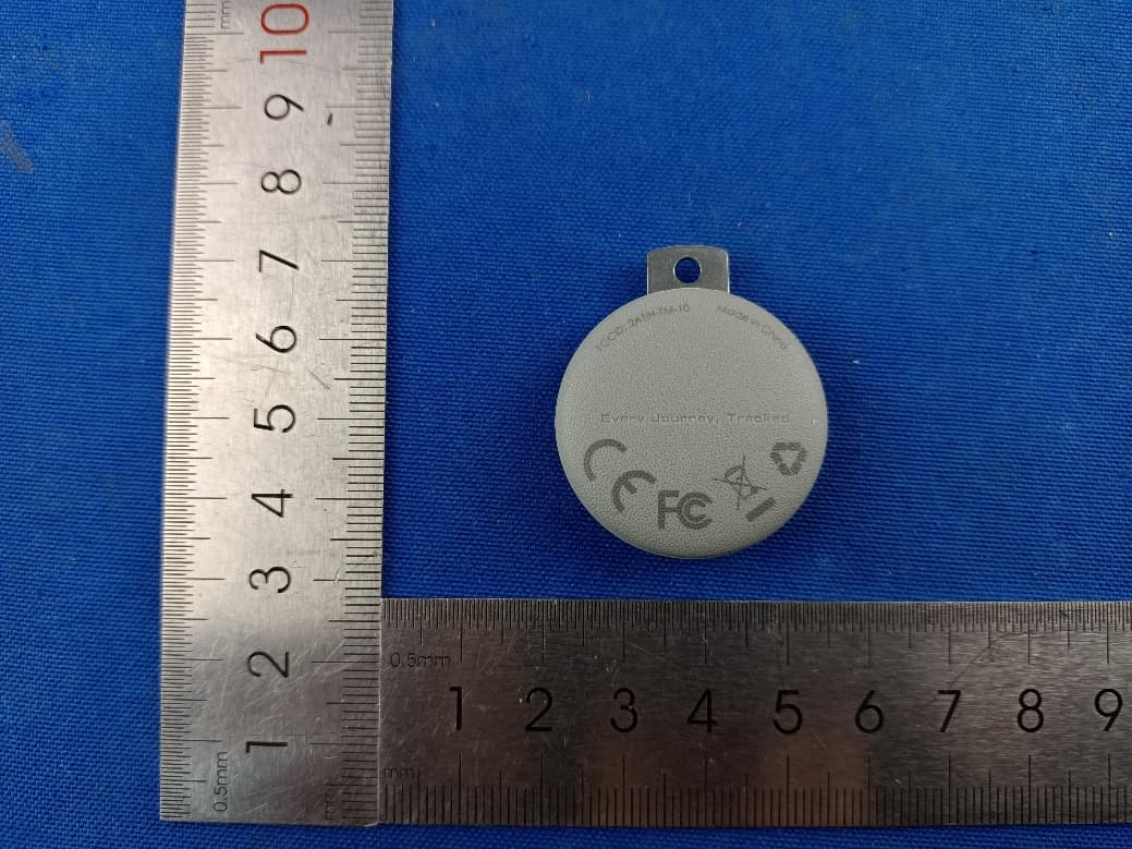
2ATIH-TM-10
Sep 07, 2024Smart Bluetooth Tracker
Equipment Class
DTS - Digital Transmission System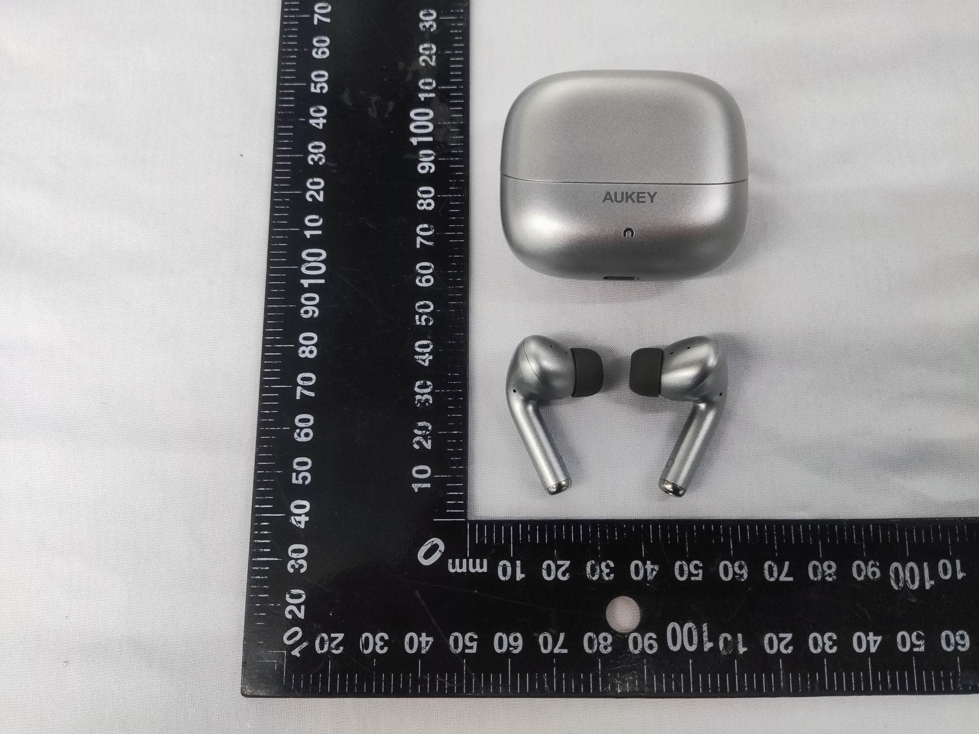
2ATIH-EP-B1
Aug 15, 2024True Wireless Earbuds with Hybrid ANC
Equipment Class
DSS - Part 15 Spread Spectrum Transmitter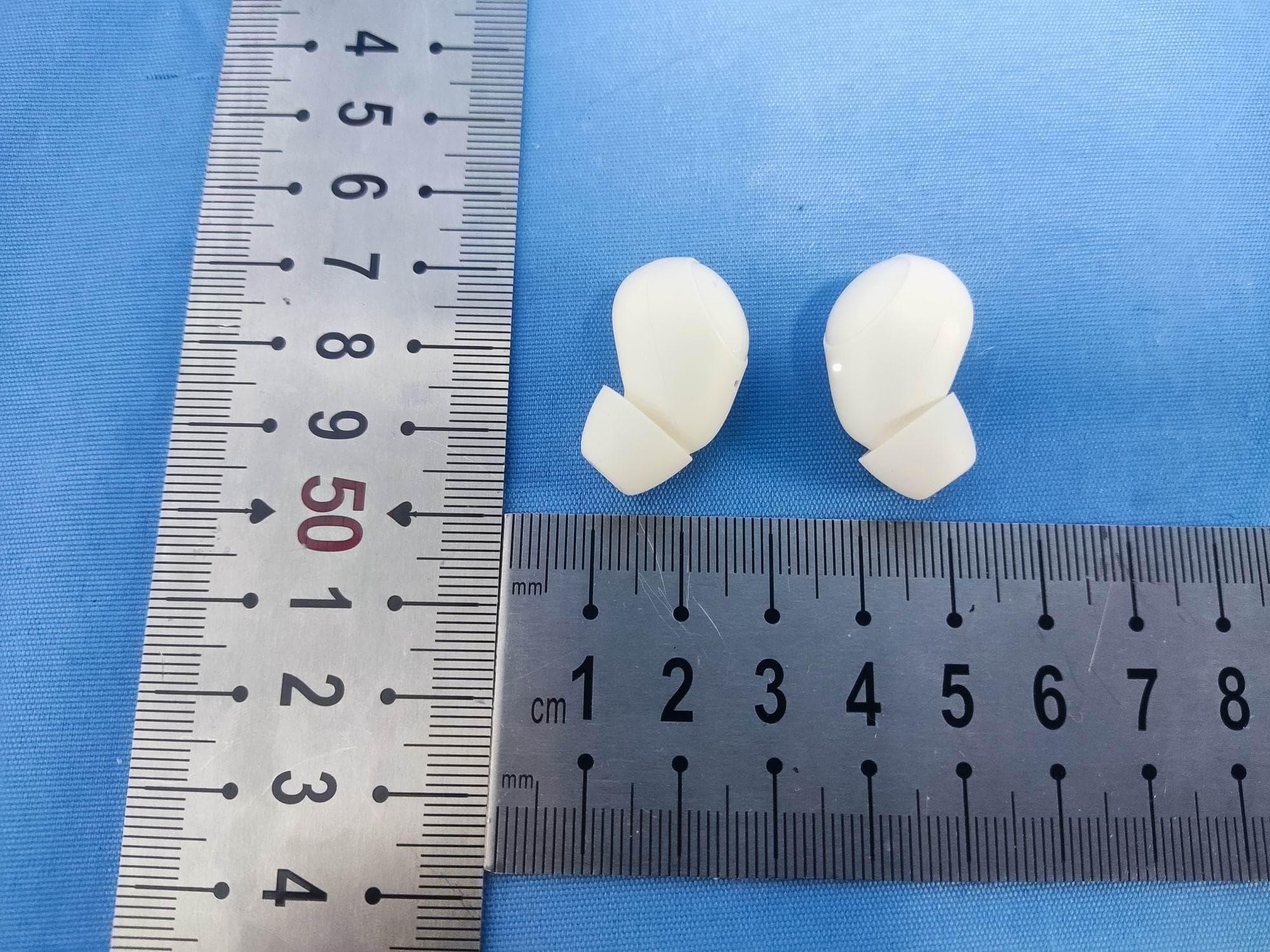
2ATIH-EP-M3A
Jul 30, 2024True Wireless Earbuds
Equipment Class
DSS - Part 15 Spread Spectrum Transmitter
2ATIH-LC-MC311A
Jul 21, 2024MagFusion 3-in-1 Pro Qi2 Magnetic Fast Wireless Charging Station with Active Cooling System
Equipment Class
DCD - Part 15 Low Power Transmitter Below 1705 kHz
2ATIH-SW2P
Dec 09, 2023SmartWatch
Equipment Class
DXX - Part 15 Low Power Communication Device Transmitter