2ATIHEPT25Bluetooth wireless earbuds
Aukey Technology Co.,Ltd.
Click to zoom
Application Details
- Equipment Class
- DSS - Part 15 Spread Spectrum Transmitter
- Date of Grant
- Apr 26, 2021
- Application Purpose
- Original Equipment
- Date of Application
- Apr 26, 2021
- Equipment Note
- Bluetooth wireless earbuds
- Frequency Range
- 2402.00000000 - 2480.00000000
- Company
- Aukey Technology Co.,Ltd.
- Country
- China
Documents & Files
Document Text
Text extracted from the exhibit documents filed with the FCC. Open a document above to read the original.
Users Manual
FAQ The earbuds are on, but not connecting to my device For the earbuds and your device to establish a connection, you need to p ut them both in pairing mod e. Please follow the instructions in the Pairi ng secti on of this manual. - 01 - English Deutsch Français Español Italiano 01~09 10~18 19~27 28~36 37~45 日本語 46~53 Contents User Manual wireless earbuds Model: EP-T25 - 02 - - 03 -- 04 -- 05 -- 06 -- 07 -- 08 -- 09 - Tha nk y ou for purchasing the AUKEY EP-T25 True Wirele ss Earbuds. Please read this us er manual carefully and keep it for future reference. If you need any assistance, ple ase contact our support team with your prod uct model numb er and Ama zon ord er number. Package Contents True Wirele ss Earbuds Cha rgi ng Case Three Pairs of Ear-Tips (S/M/L) USB-A to C Cable Us er Manual Qui ck Sta rt Gu ide Wa rra nty Card Product Diagram Getting Started Charging Fully charge the charging case before first use. To charge, connect the case to a USB charger or charging port with the included USB-A to C cable. When all 4 LED charging indicator lights are blue, the case is fully charged. Charging takes around 1.5 hours, and after being fully charged, the case can fully charge the earbuds 4 times. The earbuds should be stored in the case when not in use. When the earbuds are charging in the case (with the case itself not charging) and the case is opened, the LED charging indicator is solid red. When the red indicator turns blue, the earbuds are fully charged. Specifications Earbuds Charging Case Model Technology Driver (each channel) Sensitivity Frequency Range Impedance Microphone Type Microphone Sensitivity Microphone Frequency Range Charging Time Battery Life Battery Type Operating Range IP Rating Weight EP-T25 BT 5, A2DP, AVRCP, HFP, HSP, AAC 1 x 6mm / 0.24” speaker driver 90 ±3dB SPL (at 1kHz/1mW) 20Hz – 20kHz 16 ohm ±15% MEMS (microphone chip) -38dB ±1dB (at 1kHz) 100Hz – 10kHz 1 hour Up to 5 hours Li-polymer (2 x 40mAh) 10m / 33ft IPX5 7g / 0.25oz (pair) Cha rgi ng Input Cha rgi ng Time Battery Type Numb er of Earbuds Recharges Wei ght DC 5V 1.5 hours Li-po lymer (350mAh) 4 times (pair) 28g / 0. 99oz Turning On / Off Turn On Turn Off Pairing Starting with the earbuds in the case: Using the Left/Right Earbud Only Starting with the earbuds in the case: Regular Use After Pairing Once the earbuds are successfully paired with your device, they can be switched on and off as follows: Open the lid of the charging case. Both earbuds will turn on automatically and connect with each other Turn on the pairing function on the device you want to pair with the earbuds From the list of available devices, find and select “AUKEY EP-T25” If a code or PIN is required for pairing, enter “0000” Controls & LED Indicators Streaming Audio Once paired, you can wirelessly stream audio from your device to the earbuds. Music will automatically pause when you receive an incoming phone call and resume once the call has ended. 1. 2. 3. 4. Take the left/right earbud out Turn on the pairing function on the device you want to pair with the earbud From the list of available devices, find and select “AUKEY EP-T25” 1. 2. 3. Open the lid of the charging case, then both earbuds will turn on and connect with each other automatically To power off, put the earbuds back in the charging case and close the lid, and they will begin charging ● ● When you turn on the earbuds, they will automatically reconnect to the last-paired device or enter pairing mode if no paired device is found To clear the pairing list, touch and hold the touch-sensitive panels on both earbuds for 10 seconds after powering off both earbuds In pairing mode, the earbuds will automatically turn off after 2 minutes if no devices are paired If one of the earbuds has no sound output, put both earbuds back into the charging case and take them out again The wireless operating range is 10m (33ft). If you exceed this range, the earbuds will disconnect from your paired device. The connection will be re-established if you re-enter the wireless range within 2 minutes. The earbuds will automatically reconnect to the last-paired device. To connect with other devices, repeat the previous pairing steps ● ● ● ● ● Keep away from liquids and extreme heat Don’t use the earbuds at high volume for extended periods, as this may cause permanent hearing damage or loss CE Statement Max RF power level: BT classic (2402–2480MHz): 2.1dBm RF exposure assessment has been performed to prove that this unit will not generate the harmful EM emission above the reference level as specified in EC Council Recommendation (1999/519/EC). CAUTION: RISK OF EXPLOSION IF BATTERY IS REPLACED BY AN INCORRECT TYPE. DISPOSE OF USED BATTERIES ACCORDING TO THE INSTRUCTIONS. Hereby, A ukey Technology Co., Ltd. d eclares that the radio equipment type (True Wireless Earbuds, EP-T25) is in compliance with Directive 2014/53/EU. ● ● Notes Play or pause Sk ip to next track Sk ip to previous track Tap the touch-sensitive panel on either earbud Double-tap the touch-sensitive panel on right earbud Double-tap the touch-sensitive panel on left earbud Taking Calls Answer or end a call Reject an incoming call Us e Siri or other voi ce assistants Double-tap the touch-sensitive panel on either earbud to answer or end a call. If there’s a second incoming call, double-tap the touch-sensitive panel on either earbud to answer the second call and end the first call; or touch and hold the touch-sensitive panel on either earbud for 2 seconds to answer the second call and put the first call on hold Touch and hold the touch-sensitive panel on either earbud for 2 seconds While your device is connected, triple-tap the touch-sensitive panel on either earbud Status Case charging Case fully charged LED Battery Level Indicator Flashing blue Solid blue Status Earbuds charging Earbuds fully charged LED Charging Indicator Red Blue Warranty & Customer Support For questions, support, or warranty claims, contact us at the address below that …
Text truncated - open the document above for the full version.
Cover Letter(s)
Aukey Technology Co., Ltd. Room 102, Building P09, South China City Electronic trading center, Longgang District, Shenzhen, 518111 China Agent Authorization Company: Aukey Technology Co., Ltd. Address: Room 102, Building P09, South China City Electronic trading center, Longgang District, Shenzhen, 518111 China Product Name: wireless earbuds Model Number(s): EP-T25 Product Description: Bluetooth wireless earbuds We authorize MiCOM Labs Inc., 575 Boulder Court, Pleasanton, California 94566, USA, to act on our behalf on all matters concerning the certification of above named equipment. We declare that MiCOM Labs Inc. is allowed to forward all information related to the approval and certification of equipment to the regulatory agencies as required and to discuss any issues concerning the approval application. Any and all acts carried out by MiCOM Labs on our behalf shall have the same effect as acts of our own. Signature: Date: Aug. 13, 2020 Name: Jiaguang Zhou Title: General Manager Company: Aukey Technology Co., Ltd.
Cover Letter(s)
AukeyTechnologyCo.,Ltd. Room102,BuildingP09,SouthChinaCityElectronictradingcenter,LonggangDistrict, Shenzhen,518111China OfficeofEngineeringTechnology FederalCommunicationsCommission 7435OaklandMillsRoad Columbia,MD21046 USA Date:Apr.13,2021 Subject;RequestforConfidentiality FCCID:2ATIHEPT25 ToWhomItMayConcern, PursuanttotheprovisionsoftheCommission’srulesTitle47Sections§0.457and§0.459,we arerequestingtheCommissiontowithholdthefollowingattachment(s)asconfidential documentsfrompublicdisclosureindefinitely. Thesedocumentscontaindetailedsystemandequipmentdescriptionsandareconsideredas proprietaryinformationinoperationoftheequipment.Thepublicdisclosureofthesedocuments mightbeharmfultoourcompanyandwouldgivecompetitorsanunfairadvantageinthemarket. SchematicDiagram BlockDiagram OperationalDescription Itisourunderstandingthatallmeasurementtestreports,FCCIDlabelformatand correspondenceduringthecertificationreviewprocesscannotbegrantedasconfidential documentsandthisinformationwillbeavailableforpublicreviewoncethegrantofequipment authorizationisissued. Sincerely, Signature: Name:JiaguangZhou Title:GeneralManager
External Photos
External Photos WHOLE VIEW OF EUT TOP VIEW OF EUT BOTTOM VIEW OF EUT FRONT VIEW OF EUT BACK VIEW OF EUT LEFT VIEW OF EUT RIGHT VIEW OF EUT Left VIEW OF EUT(PORT) Right VIEW OF EUT(PORT) Charging Dock TOP VIEW OF EUT BOTTOM VIEW OF EUT FRONT VIEW OF EUT BACK VIEW OF EUT LEFT VIEW OF EUT RIGHT VIEW OF EUT VIEW OF EUT(port)-1 VIEW OF EUT(port)-2
ID Label/Location Info
FCC ID Label Location The product does not have enough space to place the label, and FCC ID label is reflected in the user manual and package, as below:
Internal Photos
Internal Photos Left OPEN VIEW OF EUT VIEW OF BATTERY INTERNAL VIEW OF EUT-1 INTERNAL VIEW OF EUT-2 INTERNAL VIEW OF EUT-3 INTERNAL VIEW OF EUT-4 BT Antenna Right OPEN VIEW OF EUT VIEW OF BATTERY INTERNAL VIEW OF EUT-1 INTERNAL VIEW OF EUT-2 INTERNAL VIEW OF EUT-3 INTERNAL VIEW OF EUT-4 BT Antenna Charging Dock OPEN VIEW OF EUT VIEW OF BATTERY INTERNAL VIEW OF EUT-1 INTERNAL VIEW OF EUT-2
RF Exposure Info
RF EXPOSURE EVALUATION 1. PRODUCT INFORMATION Product Description wireless earbuds Model Name EP-T25 FCC ID 2ATIHEPT25 2. EVALUATION METHOD According to 447498 D01 General RF Exposure Guidance v06 The 1-g and 10-g SAR test exclusion thresholds for 100 MHz to 6 GHz at test separation distances ≤ 50 mm are determined by: [(max. power of channel, including tune-up tolerance, mW)/(min. test separation distance, mm)] ·[√f(GHz)] ≤ 3.0 for 1-g SAR and ≤ 7.5 for 10-g extremity SAR. Where f(GHz) is the RF channel transmit frequency in GHz Power and distance are rounded to the nearest mW and mm before calculation 3. CALCULATION P t =4.083dBm=2.56mW The value of the Maximum output power P t is referred to the test report of the CFR47 §15.247. The result for RF exposure evaluation SAR=(2.56mW /5mm) .[√2.480GHz)]=0.80<3.0 for 1-g SAR and ≤ 7.5 for 10-g extremity SAR. 4. CONCLUSION The SAR evaluation is not required.
Test Report
Page 1 of 83 FCC Test Report Report No.: AGC08574210401FE03 FCC ID : 2ATIHEPT25 APPLICATION PURPOSE : Original Equipment PRODUCT DESIGNATION : wireless earbuds BRAND NAME : AUKEY MODEL NAME : EP-T25 APPLICANT : Aukey Technology Co., Ltd DATE OF ISSUE : Apr. 13, 2021 STANDARD(S) : FCC Part 15.247 REPORT VERSION : V1.0 Attestation of Global Compliance (Shenzhen) Co., Ltd Report No.: AGC08574210401FE03 Page 2 of 83 REPORT REVISE RECORD Report Version Revise Time Issued Date Valid Version Notes V1.0 / Apr. 13, 2021 Valid Initial Release Report No.: AGC08574210401FE03 Page 3 of 83 TABLE OF CONTENTS 1. VERIFICATION OF CONFORMITY .................................................................................................................. 5 2. GENERAL INFORMATION .............................................................................................................................. 6 2.1. PRODUCT DESCRIPTION ........................................................................................................................ 6 2.2. TABLE OF CARRIER FREQUENCYS ....................................................................................................... 6 2.3. RECEIVER INPUT BANDWIDTH .............................................................................................................. 7 2.4. EXAMPLE OF A HOPPING SEQUENCY IN DATA MODE ......................................................................... 7 2.5. EQUALLY AVERAGE USE OF FREQUENCIES AND BEHAVIOUR ......................................................... 7 2.6. RELATED SUBMITTAL(S) / GRANT (S) .................................................................................................... 8 2.7. TEST METHODOLOGY ............................................................................................................................. 8 2.8. SPECIAL ACCESSORIES ......................................................................................................................... 8 2.9. EQUIPMENT MODIFICATIONS ................................................................................................................. 8 2.10. ANTENNA REQUIREMENT..................................................................................................................... 8 3. MEASUREMENT UNCERTAINTY ................................................................................................................... 9 4. DESCRIPTION OF TEST MODES ................................................................................................................. 10 5. SYSTEM TEST CONFIGURATION ................................................................................................................ 11 5.1. CONFIGURATION OF EUT SYSTEM ...................................................................................................... 11 5.2. EQUIPMENT USED IN TESTED SYSTEM .............................................................................................. 11 5.3. SUMMARY OF TEST RESULTS .............................................................................................................. 11 6. TEST FACILITY .............................................................................................................................................. 12 7. PEAK OUTPUT POWER ................................................................................................................................ 13 7.1. MEASUREMENT PROCEDURE ............................................................................................................. 13 7.2. TEST SET-UP (BLOCK DIAGRAM OF CONFIGURATION) .................................................................... 13 7.3. LIMITS AND MEASUREMENT RESULT .................................................................................................. 14 8. 20DB BANDWIDTH ........................................................................................................................................ 26 8.1. MEASUREMENT PROCEDURE ............................................................................................................. 26 8.2. TEST SET-UP (BLOCK DIAGRAM OF CONFIGURATION) .................................................................... 26 8.3. LIMITS AND MEASUREMENT RESULTS ............................................................................................... 27 9. CONDUCTED SPURIOUS EMISSION........................................................................................................... 33 9.1. MEASUREMENT PROCEDURE ............................................................................................................. 33 Report No.: AGC08574210401FE03 Page 4 of 83 9.2. TEST SET-UP (BLOCK DIAGRAM OF CONFIGURATION) .................................................................... 33 9.3. MEASUREMENT EQUIPMENT USED .................................................................................................... 33 9.4. LIMITS AND MEASUREMENT RESULT .................................................................................................. 33 10. RADIATED EMISSION ................................................................................................................................. 46 10.1. MEASUREMENT PROCEDURE ........................................................................................................... 46 10.2. TEST SETUP ......................................................................................................................................... 48 10.3. LIMITS AND MEASUREMENT RESULT ............................................................................................... 49 10.4. TEST RESULT........................................................................................................................................ 49 11. NUMBER OF HOPPING FREQUENCY ...................................................................................…
Text truncated - open the document above for the full version.
Test Report
Report No.: AGC08574210401FE03 Page 65 of 83 APPENDIX A: PHOTOGRAPHS OF TEST SETUP RADIATED EMISSION TEST SETUP BELOW 1GHz RADIATED EMISSION TEST SETUP ABOVE 1GHz Report No.: AGC08574210401FE03 Page 66 of 83 CONDUCTED TEST SETUP Report No.: AGC08574210401FE03 Page 67 of 83 APPENDIX B: PHOTOGRAPHS OF EUT WHOLE VIEW OF EUT TOP VIEW OF EUT Report No.: AGC08574210401FE03 Page 68 of 83 BOTTOM VIEW OF EUT FRONT VIEW OF EUT Report No.: AGC08574210401FE03 Page 69 of 83 BACK VIEW OF EUT LEFT VIEW OF EUT Report No.: AGC08574210401FE03 Page 70 of 83 RIGHT VIEW OF EUT Left VIEW OF EUT(PORT) Report No.: AGC08574210401FE03 Page 71 of 83 OPEN VIEW OF EUT VIEW OF BATTERY Report No.: AGC08574210401FE03 Page 72 of 83 INTERNAL VIEW OF EUT-1 INTERNAL VIEW OF EUT-2 Report No.: AGC08574210401FE03 Page 73 of 83 INTERNAL VIEW OF EUT-3 INTERNAL VIEW OF EUT-4 BT Antenna Report No.: AGC08574210401FE03 Page 74 of 83 Right VIEW OF EUT(PORT) OPEN VIEW OF EUT Report No.: AGC08574210401FE03 Page 75 of 83 VIEW OF BATTERY INTERNAL VIEW OF EUT-1 Report No.: AGC08574210401FE03 Page 76 of 83 INTERNAL VIEW OF EUT-2 INTERNAL VIEW OF EUT-3 Report No.: AGC08574210401FE03 Page 77 of 83 INTERNAL VIEW OF EUT-4 Charging Dock TOP VIEW OF EUT BT Antenna Report No.: AGC08574210401FE03 Page 78 of 83 BOTTOM VIEW OF EUT FRONT VIEW OF EUT Report No.: AGC08574210401FE03 Page 79 of 83 BACK VIEW OF EUT LEFT VIEW OF EUT Report No.: AGC08574210401FE03 Page 80 of 83 RIGHT VIEW OF EUT VIEW OF EUT(port)-1 Report No.: AGC08574210401FE03 Page 81 of 83 VIEW OF EUT(port)-2 OPEN VIEW OF EUT
Test Report
Report No.: AGC08574210401FE03 Page 82 of 83 VIEW OF BATTERY INTERNAL VIEW OF EUT-1 Report No.: AGC08574210401FE03 Page 83 of 83 INTERNAL VIEW OF EUT-2 ----END OF REPORT---- Conditions of Issuance of Test Reports 1. All samples and goods are accepted by the Attestation of Global Compliance (Shenzhen) Co., Ltd (the “Company”) solely for testing and reporting in accordance with the following terms and conditions. The company provides its services on the basis that such terms and conditions constitute express agreement between the company and any person, firm or company requesting its services (the “Clients”). 2. Any report issued by Company as a result of this application for testing services (the “Report”) shall be issued in confidence to the Clients and the Report will be strictly treated as such by the Company. It may not be reproduced either in its entirety or in part and it may not be used for advertising or other unauthorized purposes without the written consent of the Company. The Clients to whom the Report is issued may, however, show or send it, or a certified copy thereof prepared by the Company to its customer, supplier or other persons directly concerned. The Company will not, without the consent of the Clients, enter into any discussion or correspondence with any third party concerning the contents of the Report, unless required by the relevant governmental authorities, laws or court orders. 3.The Company shall not be called or be liable to be called to give evidence or testimony on the Report in a court of law without its prior written consent, unless required by the relevant governmental authorities, laws or court orders. 4. The non-CMA report issued by AGC is only permitted to be used by the client as internal reference use and shall not be used for public demonstration purpose. 5. In the event of the improper use of the report as determined by the Company, the Company reserves the right to withdraw it, and to adopt any other additional remedies which may be appropriate. 6. Samples submitted for testing are accepted on the understanding that the Report issued cannot form the basis of, or be the instrument for, any legal action against the Company. 7. The Company will not be liable for or accept responsibility for any loss or damage however arising from the use of information contained in any of its Reports or in any communication whatsoever about its said tests or investigations. 8.Clients wishing to use the Report in court proceedings or arbitration shall inform the Company to that effect prior to submitting the sample for testing. 9. The Company is not responsible for recalling the electronic version of the original report when any revision is made to them. The Client assumes the responsibility to providing the revised version to any interested party who uses them. 10. Subject to the variable length of retention time for test data and report stored hereinto as otherwise specifically required by individual accreditation authorities, the Company will only keep the supporting test data and information of the test report for a period of six years. The data and information will be disposed of after the aforementioned retention period has elapsed. Under no circumstances shall we provide any data and information which has been disposed of after retention period. Under no circumstances shall we be liable for damage of any kind, including (but not limited to) compensatory damages, lost profits, lost data, or any form of special, incidental, indirect, consequential or punitive damages of any kind, whether based on breach of contract of warranty, tort (including negligence), product liability or otherwise, even if we are informed in advance of the possibility of such damages.
Test Setup Photos
Test Setup Photos RADIATED EMISSION TEST SETUP BELOW 1GHz RADIATED EMISSION TEST SETUP ABOVE 1GHz CONDUCTED TEST SETUP
Contact Information
Applicant
Jiaguang Zhou(Manager)
Technical Contact
Test Firm
Attestation of Global Compliance (Shenzhen) Co., LDoris Li
[email protected]+86-755-25234088
Technical Specifications
| # | Rule Parts | Frequency Range | Power Output |
|---|---|---|---|
| 1 | 15C | 2.40 GHz - 2.48 GHz | 2.60 mW |
Other Applications from Aukey Technology Co.,Ltd.
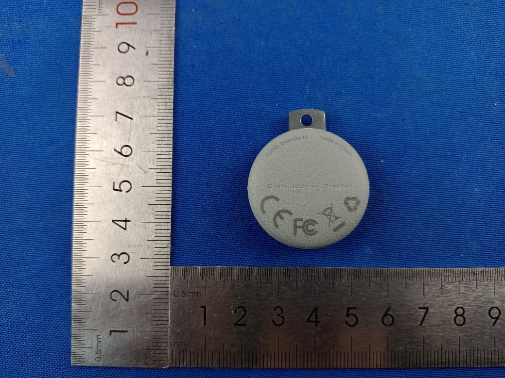
2ATIH-TM-10
Sep 07, 2024Smart Bluetooth Tracker
Equipment Class
DTS - Digital Transmission System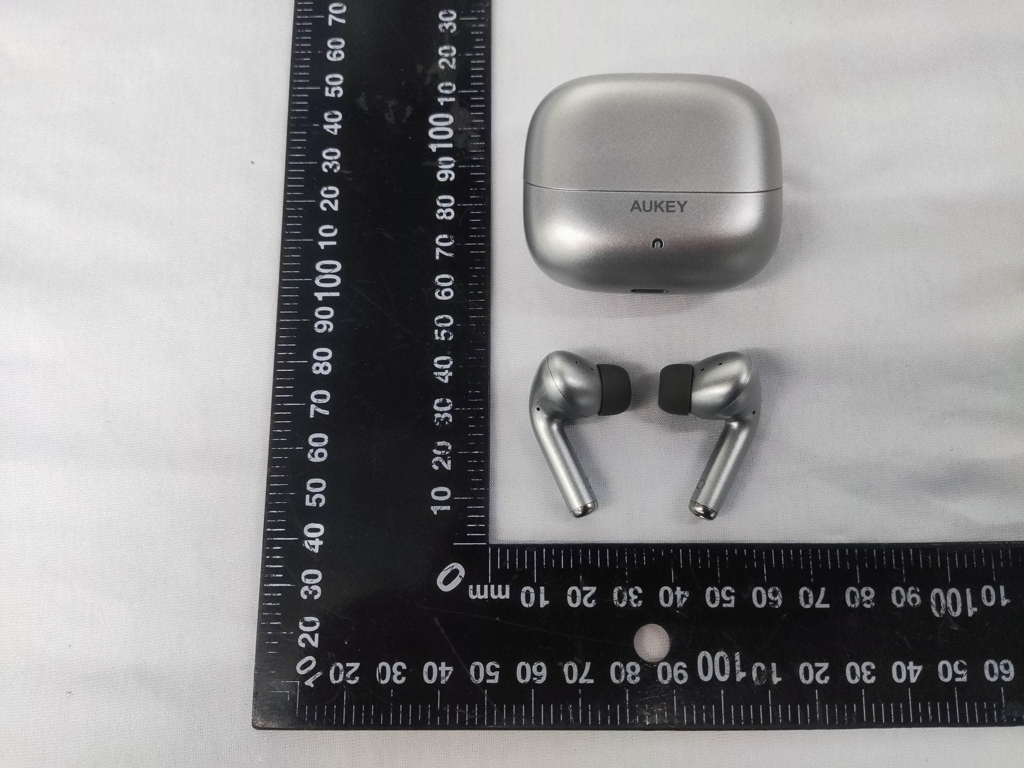
2ATIH-EP-B1
Aug 15, 2024True Wireless Earbuds with Hybrid ANC
Equipment Class
DSS - Part 15 Spread Spectrum Transmitter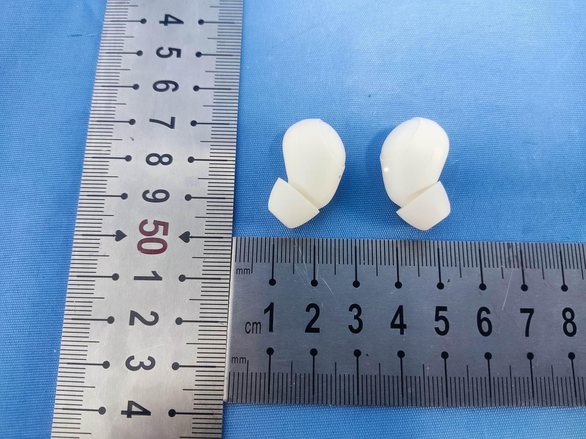
2ATIH-EP-M3A
Jul 30, 2024True Wireless Earbuds
Equipment Class
DSS - Part 15 Spread Spectrum Transmitter
2ATIH-LC-MC311A
Jul 21, 2024MagFusion 3-in-1 Pro Qi2 Magnetic Fast Wireless Charging Station with Active Cooling System
Equipment Class
DCD - Part 15 Low Power Transmitter Below 1705 kHz
2ATIH-SW2P
Dec 09, 2023SmartWatch
Equipment Class
DXX - Part 15 Low Power Communication Device Transmitter