2ATK8SHRFWireless Thermometer
Ningbo Shuanghe Hongsheng Electronic Technology Co.,Ltd
Click to zoom
Application Details
- Equipment Class
- DSC - Part 15 Security/Remote Control Transmitter
- Date of Grant
- Jul 23, 2020
- Application Purpose
- Original Equipment
- Date of Application
- Jul 23, 2020
- Equipment Note
- Wireless Thermometer
- Frequency Range
- 433.92000000 - 433.92000000
- Country
- China
Documents & Files
Document Text
Text extracted from the exhibit documents filed with the FCC. Open a document above to read the original.
Users Manual
WIRELESS THERMOMETER Instruction manual 1.Description of parts -1- Fig. 1: Receiver front side A 3 A 4 A 6 A 7 A 8 A 9 A 10 A1: A8: Time/Alarm RCC symbol A2: A9: Date Indoor low power index A3: A10: Outdoor temperature Alarm symbol A4:Outdoor low power index A5: MAX and MIN temperature A6:Indoor humidity A7:Indoor temperature A 1 A 2 A 5 B1 B2 B3 B5 Fig. 2: Receiver backside B6 B4 B1:Buttons Hanging hole B2: B3: 5V micro usb input B4: RESET button B5: B6: Support Battery door -2- Fig. 3: Transmitter -3- Fig. 3 C1:Wall mounting hole C2:LED index C4: Switch 1-2-3 for channel selection C5:TX button C 1 C 2 C 5 C 4 2. Before you start using it • Please make sure to read the instruction manual carefully. This information will help you to familiarise yourself with your new device, to learn all of its functions and parts, to find out important details about its first use and how to operate it and to get advice in the event of a malfunction. • Following and respecting the instructions in your manual will prevent damage to your instrument and loss of your statutory rights arising from defects due to incorrect use. C 3 C3:Battery compartment • We shall not be liable for any damage occurring as a result of non following of these instructions. Likewise,we take no responsibility for any incorrect readings and for any consequences which may result from them. • Please take particular note of the safety advice! • Please keep this instruction manual for future reference. 3.Scope of delivery • Wireless weather station (Receiver) • Micro USB wire • Outdoor transmitter (CH1) • Instruction manual 4.Specifications • Measuring range indoors:Temperature -10°C~+50°C(14°F~122°F) Humidity 20%~95%. • Measuring range outdoors: Temperature -40°C~+60°C(-40°F~140°F). • Accuracy : Temperature +/-1°C(2°F) between 0°C to 50°C,otherwise +/-2°C(4°F). Humidity +/-5% between 30% to 70%,otherwise +/-8%. • Working temperature and humidity : -10°C~+50°C (14°F~122°F) and 20%~95%. • Storage temperature and humidity : -10°C~+60°C (14°F~140°F) and 10%~95%. • Power Consumption: Receiver 2 X 1,5V AAA or 5V/1A micro usb input. Transmitter 2 X 1,5V AAA. • RCC function: DCF and WWVB choice. • Transmission distance: 60m in free field. • Transmission frequency:433.92MHZ. -4- • This product is exclusively intended for the field of application described above. It should only be used as described within these instructions. 5.For your safety • Unauthorized repairs, modifications or changes to the product are prohibited. • Time date display. • Alarm function. -5- Caution! Risk of injury: • Keep these instruments and the batteries out of the reach of children. • Batteries must not be thrown into a fire, short-circuited, taken apart or recharged. Risk of explosion! • Batteries contain harmful acids. Low batteries should be changed as soon as possible to prevent damage caused by leaking. • Never use a combination of old and new batteries together, nor batteries of different types. • Wear chemical-resistant protective gloves and safety glasses when handling leaking batteries. ! Important information on product safety! • Do not place your device near extreme temperatures, vibrations or shocks. • Protect it from moisture. • The outdoor transmitter is protected against splash water, but is not watertight. Choose a shady and dry position for the outdoor transmitter. ! • Place both instruments on a desk with a distance of approximately 1.5 meter. Avoid getting close to possible interference sources (Electronic devices and radio installations). • Remove the protective foil from the display of the receiver. • Connect the basic station to the attached micro-usb wire,and put USB port into 5V/1A power part,like computer,the charger of phone,etc. (This way the backlight will be light all time.) 6.1 Inserting the batteries in the receiver 6. Getting started -6- • Or remove the battery cover and insert two new batteries 1,5V AAA,polarity as illustrated,Close the battery compartment again. (This way the backlight will be not light all the time, it need press button to turn on the backlight,and the backlight will light few seconds then auto turn off.) • The device will alert you with a beep and all LCD segments will be displayed for a short moment. • The default: DCF: TIME:2020-1-1, 6:00 AL: 6:00, OFF Hour system: 24hr Temperature unit: °C WWVB: TIME:2020-1-1, 12:00 AL: 12:00, OFF Hour system: 12hr Temperature unit: °F 6.2 Inserting the batteries in the outdoor transmitter • Open the battery compartment of the outdoor transmitter. • The slide switch for channel selection is at position 1 (default). • Insert two new batteries 1,5 V AAA, polarity as illustrated. • Close the battery compartment again. • The outdoor values of the outdoor transmitter will be transmitted to the receiver. The displays of the outdoor values are flashing "--.-". • On the display of the receiver appear the channel number. • If receiver receive the signal, it will display the current temperature of transmitter in OUT position. • If the reception of the outdoor values fails within three minutes, "- -"appears on the display. Check the batteries of the transmitter and try it again. Check if there is any source of interference. • You can also start the outdoor transmitter search manually later on (for example when the outdoor transmitter is lost or the batteries are changed). • Hold the button on the receiver for three seconds, "---" blinking on the display. • Press the TX button in the battery compartment of the outdoor transmitter. • The receiver receives the values from the outdoor transmitter. 6.2.1 Reception of the outdoor values -7- • After successful installation close the battery compartment of the outdoor transmitter carefully. 6.3 Reception of the RCC frequency signal • After the reception of the outdoor values, the device will now scan the RCC frequency signal and the RCC symbol will be flashing on the display. • To avoid interference, the other buttons (except ) will no function dur…
Text truncated - open the document above for the full version.
Cover Letter(s)
Ningbo Shuanghe Hongsheng Electronic Technology Co.,Ltd No.2 Binxi south Rd Dayin Industrial Park,Yuyao,Zhejiang,China Tel: +86-574-62915615 Fax: +86-574-62913278 Email: [email protected] QA-FR-170-B 7/29/2014 FCC Authorization Date: 2020-07-08 FEDERAL COMMUNICATIONS COMMISSIONS Authorization and Evaluation Division 7435 Oakland Mills Road Columbia, MD 21046 Subject: Agent Authorization To whom it may concern: We Ningbo Shuanghe Hongsheng Electronic Technology Co.,Ltd, the undersigned, hereby authorizes Bay Area Compliance Laboratories Corporation to act on its behalf in all matters relating to application for Equipment authorization, including the signing of all documents relating to these matters. All acts carried out by Bay Area Compliance Laboratories Corporation on our behalf shall have the same effect as our own action. We, the undersigned, hereby certify that we are not subject to a denial of federal benefits, that includes FCC benefits, pursuant to Section 5301 of the Anti-Drug Abuse Act of 1988, 21 U.S.C. 862. This authorization is valid until further written notice from the applicant. Sincerely Yours, Signature: Steven Li Manager
Cover Letter(s)
Ningbo Shuanghe Hongsheng Electronic Technology Co.,Ltd No.2 Binxi south Rd Dayin Industrial Park,Yuyao,Zhejiang,China Tel: +86-574-62915615 Fax: +86-574-62913278 Email: [email protected] FCC Confidential Authorization Date: 2020-07-08 FEDERAL COMMUNICATIONS COMMISSIONS Authorization and Evaluation Division 7435 Oakland Mills Road Columbia, MD 21046 Subject: Confidentiality Request regarding application for certification of FCC ID: 2ATK8SHRF In accordance with Sections 0.457 and 0.459 of the Commission’s Rules, Grandstream Networks, Inc. hereby requests long-term confidential treatment of information accompanying this application as outlined below: Block Diagram Schematics Operation Description The above materials contain proprietary and confidential information not customarily released to the public. The public disclosure of these materials provides unjustified benefits to its competitors in the market. Sincerely Yours, Signature: Steven Li Manager
Cover Letter(s)
Ningbo Shuanghe Hongsheng Electronic Technology Co.,Ltd No.2 Binxi south Rd Dayin Industrial Park,Yuyao,Zhejiang,China Tel: +86‐574‐62915615 Fax: +86‐574‐62913278 Email: [email protected] Product Similarity Declaration Date: 2020-07-27 Dear Sir/Madam, We, Ningbo Shuanghe Hongsheng Electronic Technology Co.,Ltd hereby declare that we have a product named as Wireless thermometer, (model: SH‐006T) (FCC ID: 2ATK8SHRF ) were tested by BACL, Meanwhile, For our marketing purpose, we would like to list a series model SH‐007B, SH‐074T ,TX151 on reports and certificate. The difference between them is the model name the others are the same. We confirm that all information above is true, and we’ll be responsible for all the consequences. Please contact me if you have any question. Sincerely Yours, Signature: Steven li Manager
External Photos
Bay Area Compliance Laboratories Corp. (Shenzhen) Report No.: RSZ200615010-RF Page 1 of 3 EXHIBIT B - EUT EXTERNAL PHOTOGRAPHS Bay Area Compliance Laboratories Corp. (Shenzhen) Report No.: RSZ200615010-RF Page 2 of 3 Bay Area Compliance Laboratories Corp. (Shenzhen) Report No.: RSZ200615010-RF Page 3 of 3
ID Label/Location Info
Bay Area Compliance Laboratories Corp. (Shenzhen) Report No.: RSZ200615010-RF Page 1 of 1 EXHIBIT A - FCC ID LABEL AND LOCATION FCC ID Label FCC ID Label Location Information The label shown shall be permanently affixed at a conspicuous location on the device and be readily visible to the user at the time purchase (Labeling requirements per 2.925)
Internal Photos
Bay Area Compliance Laboratories Corp. (Shenzhen) Report No.: RSZ200615010-RF Page 1 of 2 EXHIBIT C - EUT INTERNAL PHOTOGRAPHS Bay Area Compliance Laboratories Corp. (Shenzhen) Report No.: RSZ200615010-RF Page 2 of 2 Antenna
Test Report
Note: This report must not be used by the customer to claim product certification, approval, or endorsement by A2LA* or any agency of the Federal Government. This report may contain data that are not covered by the A2LA accreditation and are marked with an asterisk “★”. BACL is not responsible for the authenticity of any test data provided by the applicant. Data included from the applicant that may affect test results are marked with an asterisk ’*’. Customer model name, addresses, names, trademarks etc. are not considered data. This report cannot be reproduced except in full, without prior written approval of the Company. Unless otherwise stated the results shown in this test report refer only to the sample(s) tested. This report is valid only with a valid digital signature. The digital signature may be available only under the Adobe software above version 7.0. FCC PART 15.231 TEST REPORT For Ningbo Shuanghe Hongsheng Electronic Technology Co.,Ltd No.2 Binxi south Rd Dayin Industrial Park, Yuyao, Zhejiang, China FCC ID: 2ATK8SHRF Report Type: Original Report Product Type: Wireless thermometer Report Number: RSZ200615010-00 Report Date: 2020-07-31 Reviewed By: Nancy Wang RF En gineer Prepared By: Bay Area Compliance Laboratories Corp. (Shenzhen) 6/F., West Wing, Third Phase of Wanli Industrial Building, Shihua Road, Futian Free Trade Zone, Shenzhen, Guangdong, China Tel: +86-755-33320018 Fax: +86-755-33320008 www.baclcorp.com.cn Bay Area Compliance Laboratories Corp. (Shenzhen) Report No.: RSZ200615010-00 FCC Part 15.231 Page 2 of 22 TABLE OF CONTENTS GENERAL INFORMATION ....................................................................................................................................... 3 PRODUCT DESCRIPTION FOR EQUIPMENT UNDER TEST (EUT) ..................................................................................... 3 OBJECTIVE ................................................................................................................................................................... 3 RELATED SUBMITTAL(S)/GRANT(S) ............................................................................................................................. 3 TEST METHODOLOGY .................................................................................................................................................. 3 MEASUREMENT UNCERTAINTY .................................................................................................................................... 4 SYSTEM TEST CONFIGURATION .......................................................................................................................... 5 JUSTIFICATION ............................................................................................................................................................. 5 SPECIAL ACCESSORIES ................................................................................................................................................. 5 EQUIPMENT MODIFICATIONS ....................................................................................................................................... 5 SUPPORT EQUIPMENT LIST AND DETAILS .................................................................................................................... 5 EXTERNAL I/O CABLE .................................................................................................................................................. 5 BLOCK DIAGRAM OF TEST SETUP ................................................................................................................................ 5 SUMMARY OF TEST RESULTS ............................................................................................................................... 6 TEST EQUIPMENT LIST AND DETAILS ............................................................................................................... 7 FCC §15.203 - ANTENNA REQUIREMENT ............................................................................................................. 8 APPLICABLE STANDARD .............................................................................................................................................. 8 ANTENNA CONNECTOR CONSTRUCTION ...................................................................................................................... 8 FCC §15.205, §15.209, §15.231 (E) - RADIATED EMISSIONS ............................................................................... 9 APPLICABLE STANDARD .............................................................................................................................................. 9 MEASUREMENT UNCERTAINTY .................................................................................................................................... 9 EUT SETUP ................................................................................................................................................................ 10 EMI TEST RECEIVER SETUP ....................................................................................................................................... 11 TEST PROCEDURE ...................................................................................................................................................... 11 CORRECTED AMPLITUDE & MARGIN CALCULATION ................................................................................................. 11 TEST RESULTS SUMMARY .......................................................................................................................................... 11 TEST DATA ................................................................................................................................................................ 11 DUTY CYCLE ..............................................................................................................…
Text truncated - open the document above for the full version.
Test Setup Photos
Bay Area Compliance Laboratories Corp. (Shenzhen) Report No.: RSZ200615010-RF Page 1 of 1 EXHIBIT D - TEST SETUP PHOTOGRAPHS Radiated Emissions View (Below 1 GHz) Radiated Emissions View (Above 1 GHz)
Contact Information
Applicant
Steven Li(Manager)
Test Firm
Bay Area Compliance Laboratories Corp. (Shenzhen)Well Wang
[email protected]+86 (0) 755 33320018
Technical Specifications
| # | Rule Parts | Frequency Range | Power Output |
|---|---|---|---|
| 1 | 15.231(e) | 433.92 MHz - 433.92 MHz | - |
Other Applications from Ningbo Shuanghe Hongsheng Electronic Technology Co.,Ltd
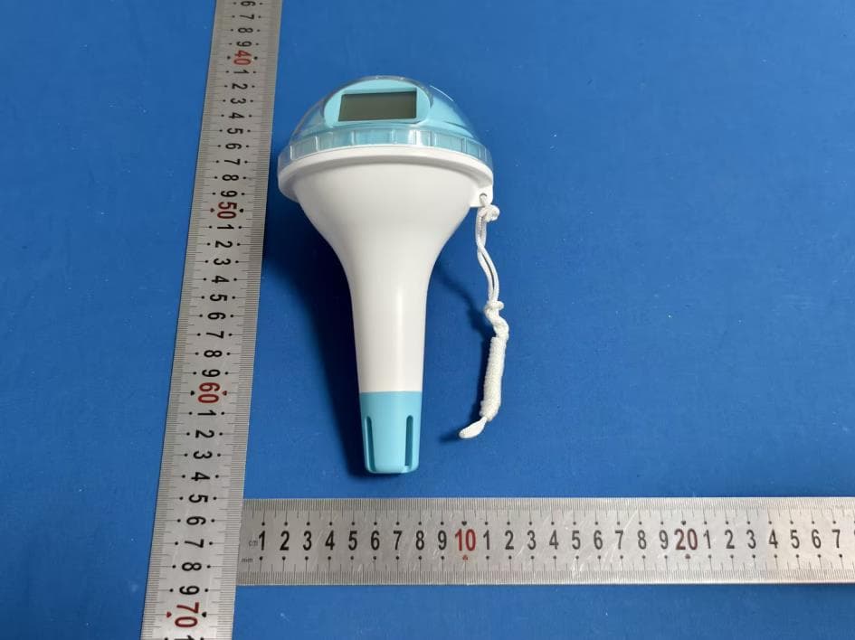
2ATK8-SH062
Jul 29, 2026DIGITAL WIRELESS POOLTHERMOMETER
Equipment Class
DSC - Part 15 Security/Remote Control Transmitter2ATK8-SH066
Sep 30, 2025Wireless Meat Thermometer (Deluxe Version)
Equipment Class
DTS - Digital Transmission System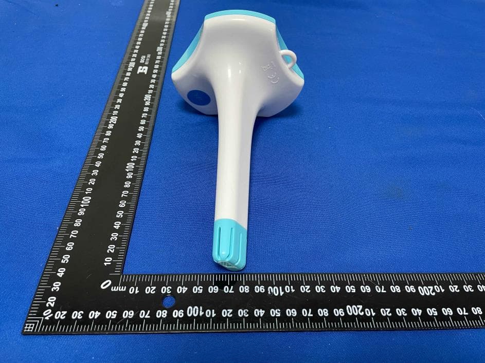
2ATK8SH-PT-002
Sep 12, 2024Circrane Solar Wireless Pool Thermometer
Equipment Class
DSC - Part 15 Security/Remote Control Transmitter