2ATKL-M2-24Satellite Communication Module
Myriota Pty Ltd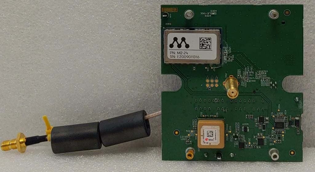
Click to zoom
Application Details
- Equipment Class
- TNB - Licensed Non-Broadcast Station Transmitter
- Date of Grant
- Mar 01, 2021
- Application Purpose
- Original Equipment
- Date of Application
- Mar 01, 2021
- Equipment Note
- Satellite Communication Module
- Frequency Range
- 399.90700000 - 400.04300000
- Company
- Myriota Pty Ltd
- Country
- Australia
Documents & Files
Document Text
Text extracted from the exhibit documents filed with the FCC. Open a document above to read the original.
Users Manual
Myriota Module M2- 24 Maker’s Guide MYRIOTA-TEC-179 26 February 2021 ©Myriota Pty Ltd 2 MYRIOTA-TEC-179-1.1 Revision History Rev Date Description of Change 1.0 February 2021 Initial version 1.1 February 2021 Updated with celltech Suggestions Related Documentation Find the latest versions of all Myriota documentation at developer.myriota.com How to Contact Us Technical Support developer.myriota.com [email protected] Sales Support [email protected] Myriota Online myriota.com 3 MYRIOTA-TEC-179-1.1 Disclaimer The information contained in this document (collectively, the “Information”) is provided to you (both the individual receiving this document and any legal entity on behalf of which such individual is acting) (“You” and “Your”) by Myriota Pty Ltd for information purposes only. — Information in this document is provided solely to enable system and software implementers to use Myriota Pty Ltd products. — Myriota Pty Ltd reserves the right to make changes without further notice to any products herein. — You are responsible for making Your own assessments concerning the Information and Myriota recommends that You assess the accuracy, completeness and relevance of the Information for Your purposes before using or relying on any of the Information. — Myriota is providing the Information to you “AS IS” and without regard to Your specific requirements. — Myriota has exercised reasonable care in preparing the Information, however Myriota does not warrant the accuracy, completeness or relevance of the Information and accepts no liability for any errors or omissions in the Information. — You acknowledge and agree that Your use of the Information is at your sole risk and that to the extent permitted by law Myriota is not liable for any loss or damage of whatever nature (direct, indirect, consequential or other) that arises in any way from Your use of or reliance on the Information. — For further information, see myriota.com or contact your Myriota sales representative. 4 MYRIOTA-TEC-179-1.1 Table of Contents 1 - System Overview 7 1.1 - Features 7 Exceptional Battery Life 7 ARM Cortex-M4 core 7 Inter-Integrated Circuit Interface (I 2 C) 7 Universal Asynchronous Receiver/Transmitter (UART) 7 Serial Peripheral Interface (SPI) 7 Low Energy Universal Asynchronous Receiver/Transmitter (LEUART) 7 Pulse Counter (PCNT) 8 Analog to Digital Converter (ADC) 8 Pre-Programmed UART Bootloader 8 1.2 - Safety and Compliance 8 1.2.1 - FCC Compliance 8 1.2.2 - Industry Canada Compliance 9 English 9 French 9 1.2.3 – Host Integration Compliance 10 2 - Physical Specification 11 2.1 - Module Dimensions and Layout 11 2.3 - Handling Information 12 2.4 - Soldering Information 12 2.5 - PCB Layout Considerations 13 5 MYRIOTA-TEC-179-1.1 2.6 - General Environmental Characteristics 14 3 - Electrical Information 15 Typical Values 15 Absolute Maximum Ratings 15 3.1 - Block Diagram 15 3.2 - Module Pin Assignment 16 3.3 - Power Consumption 19 3.4 - Electrical Specifications 20 Table 5: General Operating Conditions 20 Table 6: General Purpose Input Output 20 Table 7: Analog Digital Converter (ADC) 20 Table 8: I 2 C 21 Table 9: Temperature Sensor 21 Table 10: Test Conditions 23 4 - Radio Elements 24 4.1 Operational Frequencies 24 4.2 - Antenna Connection 24 4.3 - Antenna Integration 24 General considerations 24 4.4 - Antenna Requirements 26 UHF Transmit & Receive 26 Requirement 26 Example Use Case 26 4.4 - RF Characteristics 28 4.5 - GNSS (Global Navigation Satellite System) 28 6 MYRIOTA-TEC-179-1.1 5 - Getting Started 30 Visit the Myriota Developer Site 30 7 MYRIOTA-TEC-179-1.1 1 - System Overview The Myriota M2-24 Module (“the Module”) employs smart power features and onboard edge computing, combined with the super low bandwidth Myriota Network, to provide an ideal IoT communications solution for remote devices. 1.1 - Features Exceptional Battery Life — The Module predicts the location of satellites in the Myriota constellation, waking to transmit and receive only when a satellite is overhead — Intelligent scheduling and specially designed radio waveforms ensure reliable delivery at minimum power ARM Cortex-M4 core — Energy efficient ARM Cortex-M4 with 32-bit RISC processor capable of 1.25 Dhrystone MIPS/MHz Inter-Integrated Circuit Interface (I 2 C) — The Module acts as a master, and supports standard-mode, fast-mode and fast-mode plus speeds Universal Asynchronous Receiver/Transmitter (UART) — The Universal Asynchronous serial Receiver and Transmitter (UART) supports full- and half-duplex asynchronous UART communication. One UART supports hardware flow control Serial Peripheral Interface (SPI) — The Serial Peripheral Interface (SPI) acts as a master, and supports clock data rates up to 24MHz Low Energy Universal Asynchronous Receiver/Transmitter (LEUART) — The Low Energy UART enables two-way communication on a strict power budget. Only a 32.768 kHz clock is needed to allow UART communication up to 9600 baud/s — The LEUART makes asynchronous serial communication possible with minimal software and energy consumption. The LEUART can wake the Module from sleep mode 8 MYRIOTA-TEC-179-1.1 Pulse Counter (PCNT) — The Pulse Counter (PCNT) can be used for counting pulses on an input while the Module is in sleep mode. It can also wake up the Module from sleep mode when a prespecified number of pulses have been counted Analog to Digital Converter (ADC) — 12-bit ADC supporting VIO_REF, 2.5V or 1.25V as reference voltages Pre-Programmed UART Bootloader — The pre-programmed bootloader can be used to program the flash, retrieve Module information and dump logs 1.2 - Safety and Compliance 1.2.1 - FCC Compliance This device complies with Part 15 of the FCC Rules. Operation is subject to the following two conditions: 1. This device may not cause harmful interference, and 2. This device must accept any interference received, including interference that may cause undesired operation. ● This equipment complies with FCC radiation exposure limits set f…
Text truncated - open the document above for the full version.
Cover Letter(s)
© Celltech Labs Inc – 2021 --- Proprietary --- ______________________________________________________________________________________ 21-364 Lougheed Road, Kelowna, British Columbia, Canada V1X 7R8 Tel: 1-250-765-7650 Fax: 1-250-765-7645 Date: 22 February 2021 To: Federal Communications Commission 7435 Oakland Mills Road Columbia, Maryland 21046 USA RE: Single Modular Approval, FCC ID: 2ATKL-M2-24 This is an application for a new certification request for a Single Modular Approval as follows: Applicant: Myriota Pty Ltd. Model Name / PMN: Myriota Module Model Number / HVIN: M2-24 FCC ID: 2ATKL-M2-24 The Module is a Satellite communications Earth Station device operating between 399.907MHz and 400.043MHz. The Module was evaluated in accordance with, and meets the requirements of, 47 CFR §25. The Module meets all of the requirements of 47 CFR §15.212 for Single Modular approval. The Modular Approval Attestation is attached to this document. Should there be any questions or concerns with this filing, please feel free to contact me. Sincerely, Art Voss, P.Eng. Technical Manager 21-364 Lougheed Rd Kelowna, BC, V1X 7R8, Canada 250-765-7650 Ext 202 [email protected] www.celltechlabs.com Date: 16 February 2021 To: Federal Communications Commission Authorization and Evaluation Division 7435 Oakland Mills Rd. Columbia, MD 21046 RE: Single Modular Approval Attestation Letter for FCC ID: 2ATKL-M2-24 This is a request for a Limited Modular Approval of FCC ID: 2ATKL-M2-24 in accordance with 47 CFR 15.212(b). The following is a declaration of conditions. A ✔ denotes compliance to the applicable rule part. §15.212 Modular transmitters. (a) Single modular transmitters consist of a completely self-contained radiofrequency transmitter device that is typically incorporated into another product, host or device. Split modular transmitters consist of two components: a radio front end with antenna (or radio devices) and a transmitter control element (or specific hardware on which the software that controls the radio operation resides). All single or split modular transmitters are approved with an antenna. All of the following requirements apply, except as provided in paragraph (b) of this section. (1) Single modular transmitters must meet the following requirements to obtain a modular transmitter approval. ✔ (i) The radio elements of the modular transmitter must have their own shielding. The physical crystal and tuning capacitors may be located external to the shielded radio elements. ✔ (ii) The modular transmitter must have buffered modulation/data inputs (if such inputs are provided) to ensure that the module will comply with part 15 requirements under conditions of excessive data rates or over-modulation. ✔ (iii) The modular transmitter must have its own power supply regulation. ✔ (iv) The modular transmitter must comply with the antenna and transmission system requirements of §§15.203, 15.204(b) and 15.204(c). The antenna must either be permanently attached or employ a “unique” antenna coupler (at all connections between the module and the antenna, including the cable). The “professional installation” provision of §15.203 is not applicable to modules but can apply to limited modular approvals under paragraph (b) of this section. ✔ (v) The modular transmitter must be tested in a stand-alone configuration, i.e., the module must not be inside another device during testing for compliance with part 15 requirements. Unless the transmitter module will be battery powered, it must comply with the AC line conducted requirements found in §15.207. AC or DC power lines and data input/output lines connected to the module must not contain ferrites, unless they will be marketed with the module (see §15.27(a)). The length of these lines shall be the length typical of actual use or, if that length is unknown, at least 10 centimeters to insure that there is no coupling between the case of the module and supporting equipment. Any accessories, peripherals, or support equipment connected to the module during testing shall be unmodified and commercially available (see §15.31(i)). ✔ (vi) The modular transmitter must be equipped with either a permanently affixed label or must be capable of electronically displaying its FCC identification number. (A) Manufacturers must ensure that only transmitter control elements and radio front end components that have been approved together are capable of operating together. The transmitter module must not operate unless it has verified that the installed transmitter control elements and radio front end have been authorized together. Manufacturers may use means including, but not limited to, coding in hardware and electronic signatures in software to meet these requirements, and must describe the methods in their application for equipment authorization. (B) If the modular transmitter uses an electronic display of the FCC identification number, the information must be readily accessible and visible on the modular transmitter or on the device in which it is installed. If the module is installed inside another device, then the outside of the device into which the module is installed must display a label referring to the enclosed module. This exterior label can use wording such as the following: “Contains FCC certified transmitter module(s).” Any similar wording that expresses the same meaning may be used. The user manual must include instructions on how to access the electronic display. A copy of these instructions must be included in the application for equipment authorization. ✔ (vii) The modular transmitter must comply with any specific rules or operating requirements that ordinarily apply to a complete transmitter and the manufacturer must provide adequate instructions along with the module to explain any such requirements. A copy of these instructions must be included in the application for equipment authorization. ✔ viii) The modular transmitter must comply with any applicable RF…
Text truncated - open the document above for the full version.
Cover Letter(s)
Date: 16 February 2021 To: Federal Communications Commission 7435 Oakland Mills Road Columbia, Maryland 21046 USA RE: Confidentiality Request regarding application for certification of FCC ID: 2ATKL-M2-24 Pursuant to Sections 0.457 and 0.459 of the Commission’s Rules, we hereby request confidential treatment of information accompanying this application as outlined below: Exhibit TypeFile Name Block DiagramExhibit 12 – Block Diagram.pdf Operation DescriptionExhibit 14 – Operation Description.pdf Schematic DiagramExhibit 15 – Schematic Diagram.pdf Parts ListExhibit 16 – Bill of Material.pdf Tune-Up ProcedureExhibit 17 – Tune-Up Procedure.pdf The above materials contain trade secrets and proprietary information not customarily released to the public. The public disclosure of these materials may be harmful to the applicant and provide unjustified benefits to its competitors. The applicant understands that pursuant to Section 0.457 of the Rules, disclosure of this application and all accompanying documentation will not be made before the date of the Grant for this application. Pursuant to DA04-1705 June 15, 2004 of the Commission’s public notice, we also request temporary confidential treatment of information accompanying this application as outlined below for 180 days: Exhibit TypeFile Name User’s ManualExhibit 18 – User’s Manual.pdf External PhotosExhibit 19 – Photos - External.pdf Internal PhotosExhibit 20 – Photos – Internal.pdf Test Setup PhotosExhibit 21 – Photos – Setup.pdf Sincerely, ________________________________________________________________ Name: Janek Kaucz
External Photos
Applicant: Myriota Pty Ltd / Myriota Canada FCC ID: 2ATKL-M2-24 Test Report S/N: 45461648-R2.0 ISED ID 25148-M224 ©2021 Celltech Labs Inc. This document is not to be reproduced in whole or in part without the expressed written permission of Celltech Labs Inc. Page 12 of 25 EXHIBIT 19 – PHOTOS – DUT EXTERNAL Figure E19.1 – External – Module Top Applicant: Myriota Pty Ltd / Myriota Canada FCC ID: 2ATKL-M2-24 Test Report S/N: 45461648-R2.0 ISED ID 25148-M224 ©2021 Celltech Labs Inc. This document is not to be reproduced in whole or in part without the expressed written permission of Celltech Labs Inc. Page 13 of 25 Figure E19.2 – External – Module Bottom Applicant: Myriota Pty Ltd / Myriota Canada FCC ID: 2ATKL-M2-24 Test Report S/N: 45461648-R2.0 ISED ID 25148-M224 ©2021 Celltech Labs Inc. This document is not to be reproduced in whole or in part without the expressed written permission of Celltech Labs Inc. Page 14 of 25 Figure E19.3 – External – Module on Carrier Board - Top Applicant: Myriota Pty Ltd / Myriota Canada FCC ID: 2ATKL-M2-24 Test Report S/N: 45461648-R2.0 ISED ID 25148-M224 ©2021 Celltech Labs Inc. This document is not to be reproduced in whole or in part without the expressed written permission of Celltech Labs Inc. Page 15 of 25 Figure E19.4 – External – Carrier Board Bottom
ID Label/Location Info
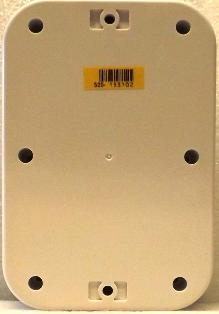
Applicant: Myriota Pty Ltd / Myriota Canada FCC ID: 2ATKL-M2-24 Test Report S/N: 45461648-R2.0 ISED ID 25148-M224 ©2021 Celltech Labs Inc. This document is not to be reproduced in whole or in part without the expressed written permission of Celltech Labs Inc. Page 10 of 25 EXHIBIT 23 – LABEL LOCATION Figure E23.1 – Label Location
Internal Photos
Applicant: Myriota Pty Ltd / Myriota Canada FCC ID: 2ATKL-M2-24 Test Report S/N: 45461648-R2.0 ISED ID 25148-M224 ©2021 Celltech Labs Inc. This document is not to be reproduced in whole or in part without the expressed written permission of Celltech Labs Inc. Page 16 of 25 EXHIBIT 20 – PHOTOS – DUT INTERNAL Figure E20.1 – Internal – Shield Removed
RF Exposure Info
Applicant: Myriota Pty Ltd / Myriota Canada FCC ID: 2ATKL-M2-24 Test Report S/N: 45461648-R2.0 ISED ID 25148-M224 ©2021 Celltech Labs Inc. This document is not to be reproduced in whole or in part without the expressed written permission of Celltech Labs Inc. Page 5 of 15 EXHIBIT 10 –FCC RF EXPOSURE (MPE) REPORT In accordance with FCC 47 CFR §1.1307(b), “In addition to the actions listed in paragraph (a) of this section, Commission actions granting construction permits, licenses to transmit or renewals thereof, equipment authorizations or modifications in existing facilities, require the preparation of an Environmental Assessment (EA) if the particular facility, operation or transmitter would cause human exposure to levels of radiofrequency radiation in excess of the limits in §§1.1310 and 2.1093 of this chapter.” FrequencyElectricMagneticPowerAveraging FieldField StrengthStrength (MHz)(V/m)(A/m)(mW/cm 2 )(minutes) 0.3 - 3.06141.63*1006 3.0 - 301842/ f4.89/ f*900/ f 2 6 30 - 30061.40.1631.06 300 - 1,500--f /3006 1,500-100,000--56 0.3 - 1.346141.63*10030 1.34 - 30824/ f2.19/ f*180/ f 2 30 30 - 30027.50.0730.230 300 - 1,500--f /150030 1,500-100,000--130 Table 1 - Limits for Maximum Permissible Exposure (MPE) FCC 47 CFR § 1.1310 f = Frequency om MHz * = Plane-wave equivalent power density RangeDensityTime (A) Limits for Occupational/Controlled Exposure (B) Limits forGeneral Population/Uncontrolled Exposure Duty Cycle Evaluation: In actual use, this device has a non-user-adjustable transmit duty cycle as follows: Transmission Duration: 260ms (0.26s) Transmission Interval: 5s Duty Cycle = 0.26s/5s = 0.052 = 5.2% The transmit duty cycle is considered in the MPE Calculation. Applicant: Myriota Pty Ltd / Myriota Canada FCC ID: 2ATKL-M2-24 Test Report S/N: 45461648-R2.0 ISED ID 25148-M224 ©2021 Celltech Labs Inc. This document is not to be reproduced in whole or in part without the expressed written permission of Celltech Labs Inc. Page 6 of 15 f 1500 S 20 = S L = S C = R 20 = R c = P T = P A = G N = f = (%) (dB) R C = S C = PASSRESULT (mW/cm 2 ) Power Density of the Device at 20cm Prediction of MPE Limit 47 CFR § 2.1091 S 20 = P A G N R C = √ P A G N S C = P A G N 4πR C 2 4πS L 4πR 20 2 S L = S L = Duty Cycle/Loss Adjusted Power (P A ): Transmit Frequency Transmit Duty Cycle = (dBi) Tx Frequency (f): RF Power at Antenna Input Port (P T ): Transmit Duty Cycle: Use Group = General Popuation 500.00 5.20 400.00 0.267 (mW/cm 2 ) (mW) 5.6 (cm) (mW/cm 2 ) 0.27 (mW/cm 2 ) 5% Power Density Limit Minimum Distance to the Radiating Element to Meet Compliance Power Density of the Device at the Compliance Distance R C 20cm S 20 at 20cm = 0.021 Power Input to Antenna Numeric Gain of the Antenna (MHz) Antenna Gain:6.00 (numeric) 26.00(mW) Cable or Other Loss:0.00 Numeric Antenna Gain (G N ):3.98 Adjust Power
Test Report
Test Report Serial Number: Test Report Date: EMC Test Report - New Filing 45461648 R3.0 Project Number: 18 March 2021 1531 Applicant: © 2021 Celltech Labs Inc, This report shall not be reproduced in any form without the expressed written consent of Celltech Labs Inc. Mobile Earth Stations (MESs) and Ancillary Terrestrial Component (ATC) FCC 47 CFR Part 25 Satellite Communications FCC Registration: CA3874 Ben Hewson, President Celltech Labs Inc. IC Registration 3874A-1 21-364 Lougheed Rd. Kelowna, BC, V1X 7R8 Canada Test Lab Certificate: 2470.01 Approved By: Equipment Operating in the Mobile-Satellite Service (MSS) Bands RSS-GEN, RSS-170 Issue 3 Level 1, McEwin Building Lot 14, North Terrace Myriota Pty Ltd.Myriota Canada 260 Holiday Inn Drive Unit 30, Building B Cambridge, ON, N3C 4E8 In Accordance With: Adelaide, SA 5000 Product Model Number / HVINProduct Name / PMN M2-24Myriota Module 2ATKL-M2-2425148-M224 Australia FCC ID:IC Registration Number Test Report S/N: 45461648 R3.0 Test Report Issue Date: 18 March 2021 ©2021 Celltech Labs Inc. This document is not to be reproduced in whole or in part without the expressed written permission of Celltech Labs Inc. Page 2 of 49 Table of Contents 1.0 DOCUMENT CONTROL ................................................................................................................................................... 4 2.0 CLIENT AND DUT INFORMATION .................................................................................................................................. 5 3.0 SCOPE .............................................................................................................................................................................. 6 4.0 TEST RESULT SUMMARY .............................................................................................................................................. 7 5.0 NORMATIVE REFERENCES ........................................................................................................................................... 8 6.0 FACILITIES AND ACCREDITATIONS ............................................................................................................................. 9 7.0 CONDUCTED POWER ................................................................................................................................................... 10 8.0 OCCUPIED BANDWIDTH AND EMISSION MASKS ..................................................................................................... 13 9.0 CONDUCTED OUT OF BAND SPURIOUS EMISSIONS .............................................................................................. 16 10.0 RADIATED SPURIOUS TX EMISSIONS ..................................................................................................................... 25 11.0 FREQUENCY STABILITY ............................................................................................................................................. 39 APPENDIX A – TEST SETUP DRAWINGS AND EQUIPMENT .......................................................................................... 42 APPENDIX B – EQUIPMENT LIST AND CALIBRATION ..................................................................................................... 47 APPENDIX C – MEASUREMENT INSTRUMENT UNCERTAINTY ..................................................................................... 48 END OF REPORT ................................................................................................................................................................. 49 Test Report S/N: 45461648 R3.0 Test Report Issue Date: 18 March 2021 ©2021 Celltech Labs Inc. This document is not to be reproduced in whole or in part without the expressed written permission of Celltech Labs Inc. Page 3 of 49 Table of Figures Figure A.1 – Test Setup Conducted Measurements ............................................................................................................. 42 Figure A.2 – Test Setup Radiated Emissions Measurements 9kHz – 30MHz ..................................................................... 43 Figure A.3 – Test Setup Radiated Emissions Measurements 30 – 1000MHz ...................................................................... 44 Figure A.4 – Test Setup Radiated Emissions Measurements 30 – 1000MHz w/ Signal Substitution .................................. 44 Figure A.5 – Test Setup Radiated Emissions Measurements 1 – 18GHz ............................................................................ 45 Figure A.6 – Test Setup Radiated Emissions Measurements > 18GHz ............................................................................... 45 Figure A.7 – Test Setup Frequency Stability Measurements ............................................................................................... 46 Table of Plots Plot 7.1 – Conducted Output Power ..................................................................................................................................... 11 Plot 8.1 – Occupied Bandwidth ............................................................................................................................................. 14 Plot 9.1 – Conducted Out of Band Emissions, Emission Mask ............................................................................................ 17 Plot 9.2 – Conducted Out of Band Emissions, 30 – 100MHz ............................................................................................... 18 Plot 9.3 – Conducted Out of Band Emissions, 100 – 500MHz ............................................................................................. 19 Plot 9.4 – Conducted Out of Band Emissions, 500 - 1000MHz ............................................................................................ 20 Plot 9.5 – Conducted Out of Band Emissions, 1 - 3GHz ..............................................................................…
Text truncated - open the document above for the full version.
Test Setup Photos
Applicant: Myriota Pty Ltd / Myriota Canada FCC ID: 2ATKL-M2-24 Test Report S/N: 45461648-R2.0 ISED ID 25148-M224 ©2021 Celltech Labs Inc. This document is not to be reproduced in whole or in part without the expressed written permission of Celltech Labs Inc. Page 14 of 22 EXHIBIT 21 – PHOTOS – EMC SETUP Figure E21.1 – Test Set Up - Conducted Measurements Applicant: Myriota Pty Ltd / Myriota Canada FCC ID: 2ATKL-M2-24 Test Report S/N: 45461648-R2.0 ISED ID 25148-M224 ©2021 Celltech Labs Inc. This document is not to be reproduced in whole or in part without the expressed written permission of Celltech Labs Inc. Page 15 of 22 Figure E21.2 – Test Set Up - Conducted Measurements Applicant: Myriota Pty Ltd / Myriota Canada FCC ID: 2ATKL-M2-24 Test Report S/N: 45461648-R2.0 ISED ID 25148-M224 ©2021 Celltech Labs Inc. This document is not to be reproduced in whole or in part without the expressed written permission of Celltech Labs Inc. Page 16 of 22 Figure E21.3 – Test Set Up - Radiated Measurements 30MHz – 1000MHz, Antenna #1 Applicant: Myriota Pty Ltd / Myriota Canada FCC ID: 2ATKL-M2-24 Test Report S/N: 45461648-R2.0 ISED ID 25148-M224 ©2021 Celltech Labs Inc. This document is not to be reproduced in whole or in part without the expressed written permission of Celltech Labs Inc. Page 17 of 22 Figure E21.4 – Test Set Up - Radiated Measurements 30MHz – 1000MHz, Antenna #2 Applicant: Myriota Pty Ltd / Myriota Canada FCC ID: 2ATKL-M2-24 Test Report S/N: 45461648-R2.0 ISED ID 25148-M224 ©2021 Celltech Labs Inc. This document is not to be reproduced in whole or in part without the expressed written permission of Celltech Labs Inc. Page 18 of 22 Figure E21.5 – Test Set Up - Radiated Measurements 1 – 4GHz, Antenna #1 Applicant: Myriota Pty Ltd / Myriota Canada FCC ID: 2ATKL-M2-24 Test Report S/N: 45461648-R2.0 ISED ID 25148-M224 ©2021 Celltech Labs Inc. This document is not to be reproduced in whole or in part without the expressed written permission of Celltech Labs Inc. Page 19 of 22 Figure E21.6 – Test Set Up - Radiated Measurements 1 – 4GHz, Antenna #2 Applicant: Myriota Pty Ltd / Myriota Canada FCC ID: 2ATKL-M2-24 Test Report S/N: 45461648-R2.0 ISED ID 25148-M224 ©2021 Celltech Labs Inc. This document is not to be reproduced in whole or in part without the expressed written permission of Celltech Labs Inc. Page 20 of 22 Figure E21.7 – Test Set Up - Frequency Stability Applicant: Myriota Pty Ltd / Myriota Canada FCC ID: 2ATKL-M2-24 Test Report S/N: 45461648-R2.0 ISED ID 25148-M224 ©2021 Celltech Labs Inc. This document is not to be reproduced in whole or in part without the expressed written permission of Celltech Labs Inc. Page 21 of 22 Figure E21.8 – Test Set Up - Frequency Stability
Contact Information
Applicant
Janek Kaucz(Mr)
Test Firm
CELLTECH LABS INC.Ben Hewson
Technical Specifications
| # | Rule Parts | Frequency Range | Power Output | Emission | Tolerance |
|---|---|---|---|---|---|
| 1 | 25 | 399.907 MHz - 400.043 MHz | 500.00 mW | 2K36G1D | 0.0001300000 % |
Other Applications from Myriota Pty Ltd
2ATKL-DB2-25
May 02, 2021Product Developers Tool Kit
Equipment Class
JAB - Part 15 Class B Digital Device