2ATLH-OM802SOM802S
Beijing ManThink Technology Co., Ltd.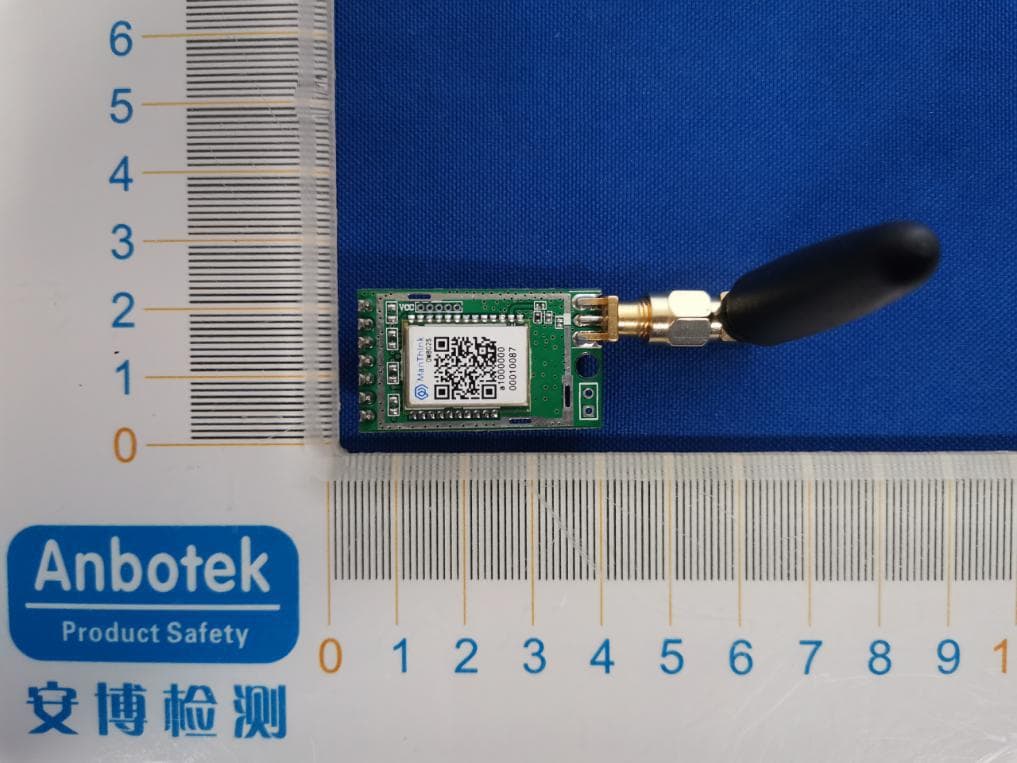
Click to zoom
Application Details
- Equipment Class
- DXX - Part 15 Low Power Communication Device Transmitter
- Date of Grant
- Oct 29, 2020
- Application Purpose
- Original Equipment
- Date of Application
- Oct 29, 2020
- Equipment Note
- OM802S
- Frequency Range
- 923.20000000 - 924.60000000
- Country
- China
Documents & Files
Document Text
Text extracted from the exhibit documents filed with the FCC. Open a document above to read the original.
Users Manual
OMx02 DataSheet 1.1 www.manthink.cn 1 / 10 T EL:+86-010-56229170 OM802S LoRa Module with Open Source OM802S is a highly integrated low-power half-duplex RF transceiver module embedding high-speed low-power MCU and high-performance RF chip with LORA modem which is capable of achieving significant longer range than existing RF transceiver based on FSK or OOK modulation. OM802S can support secondary development to realize an application of LoRaWAN with the SDK supplied by ManThink, OM802S have abundant hardware resource to realize different function which include SPI, IIC, AD and DIO. This module uses LoRa modem to improve the sensitivity up to -137dBm, significantly extending the transmission distance under a low power. Under LoRaWAN protocol, the start network can solve the problem of collision and low power consumption through gateway solution. OM802S module’s interface voltage 2.6- 3.6 V with consuming only 13 mA at the receiving mode. If there is no packet to transmit, the module consumption is only 3uA which is very suitable for a battery- powered system. Using the OM802S module in an application minimize the need or an expensive and time- consuming RF development. Fast time to market is possible with this pre-qualified module. OMx02 DataSheet 1.1 www.manthink.cn 2 / 10 T EL:+86-010-56229170 . Apply Wirelesswater/heat/gas meter reading Wireless sensor Intelligent instrument and meter Intelligent lighting control Auto data collection Remote control and sensing Smart building and security Robot control Power system monitoring Wireless warehousing, logistics management Feature LoRaWAN class-A compliant Globally unique 64-bit identifier Four band and 16 channels support Transmission distance > 5000 m Frequency AS915 High sensitivity -137dBm Maximum transmission power 20dBm Low sleep current 3uA Receiving mode current 13mA Super small size 17.8mm*13mm*2.0mm OMx02 DataSheet 1.1 www.manthink.cn 3 / 10 T EL:+86-010-56229170 Catalog 1.Module Overview ........................................................................................................................................... 4 2. Global Electrical Characteristics ........................................................................................................................ 5 3.Module Package ............................................................................................................................................. 6 3.1 Pin Definition ............................................................................................................................ 6 3.2 Module Dimensions ................................................................................................................. 7 4. Typical Application Schematic .......................................................................................................................... 8 6. Other ..................................................................................................................................................................... 9 6. 1 Contact ....................................................................................................................................... 9 7. FCC STATEMENT ............................................................................................................................................. 10 OMx02 DataSheet 1.1 www.manthink.cn 4 / 10 T EL:+86-010-56229170 1.Module Overview The OM802S is an ultra-long range, high-performance module for wireless communication. It operates in the license free frequency band . The OM802S uses Semtech’s patented LoRa modulation technique which combines Spread spectrum modulation and forward error correction techniques to increase the range and spectrum modulation and forward error correction techniques to increase the range and robustness of radio communication links compared with traditional FSK or OOK based modulation. Typically examples of OM802S receive performances are given in the following table. Table 1 : performance of LoRa with different parameters The module is solderable like a SMD component and can easily be mounted on a simple carrier board with a minimum of required external connections. Signal Bandwidth/[kHz] Spreading Factor Sensitivity/[dBm] 125 7 -123 125 12 -138 250 7 -121 250 12 -135 500 7 -116 500 12 -130 OMx02 DataSheet 1.1 www.manthink.cn 5 / 10 T EL:+86-010-56229170 2. Global Electrical Characteristics Table 2 : Global Electrical Characteristics Radio Frequency 923.2~924.6 MHz Step Frequency 1KHz Transmission Power 5~20dBm, Receiving Sensitivity -138dBm@292bps Air Transfer Rate 292bps~5.4kbps Working Humidity 10%~90% (no condensation) Working Temperature -45°C~85°C The power Supply 2.6~ 3.6V ESD(Human Body Model) 2000V Transmission Current (typical) 120mA@100mW Harmonic Suppression ≤1GHz:<-36dBm, >1GHz:< -30dBm CAD/ Receives Current(typical) 13mA Sleep Current(typical) 3uA Size 17.8mm x 13.0mm x 2.0mm Antenna Impedance 50Ω OMx02 DataSheet 1.1 www.manthink.cn 6 / 10 T EL:+86-010-56229170 3. Module Package 3.1 Pin Definition Figure 1 : description of pins and top view OM802S module has nine pins, specific definitions as the following table: Table 3 : description of the pin Pin Name Direction Function 1 S1MOSI/PD6 Input/output Refer the datasheet of KL17x 2 S1MISO/PD7 Input/output Refer the datasheet of KL17x 3 S1SS/PD4 Input/output Refer the datasheet of KL17x 4 PC7 Input/output Refer the datasheet of KL17x 5 S1SCK/PD5 Input/output Refer the datasheet of KL17x 6 NC5 - Keep the Pin float 7 NC4 - Keep the Pin float 8 NC3 - Keep the Pin float 9 NC2 - Keep the Pin float 10 NC1 - Keep the Pin float 11 GND - Digital GND 12 AND - Should be connected to antenna 13 GND Digital GND 14 I1SCL/PC1 - Refer the datasheet of KL17x 15 I1SDA/PC2 Input/output Refer the datasheet of KL17x 16 UART1_RX/PC3 Input/output Refer the datasheet of KL17x OMx02 DataSheet 1.1 www.manthink.cn 7 / 10 T EL:+86-010-56229170 17 UA…
Text truncated - open the document above for the full version.
Cover Letter(s)
Beijing ManThink Technology Co., Ltd. version01 Modular Approval Request Letter Date:2020-10-28 FCC ID:2ATLH-OM802S Type of Equipment: DXX The following requirements according to FCC Part 15.212 are met: iRF shielding The radio portion has his own shielding (see external photos). ii Buffered modulation/data inputs, has been integrated in the chipset iii Power supply regulation, is integrated iv Antenna requirements section 15.203, 15.204 b and 15.204 c The module comes withone permanently attached antenna. The spurious emission requirements are fulfilled (see attached test report). v Stand alone test configuration Please referring to test set up configuration photo vi Labelling The module has its own label. The instruction for labelling rules for the host device has been stated in the users manual vii Compliance on specific rule or operating requirements The required FCC rules has been fulfilled and all instructions for maintaining compliance has been clearly stated in the users manual viii RF Exposure, RF exposure requirements are fulfilled for portable configuration.The module must be installed in the host equipment such that at least 5mm is maintained between the antenna and users’ body; The installation and restriction of the module is clearly stated in the installation instruction of the user manual. Name: donglong Huang Job Title: Engineer Beijing ManThink Technology Co., Ltd.
External Photos
FCCID:2ATLH-OM802S ANT
ID Label/Location Info
LabelLocationOnEUT Label ProductName:OM802S ModelNo.:OM802S FCCID:2ATLH-OM802S
Internal Photos
FCCID:2ATLH-OM802S
Operational Description
version01 BeijingManThinkTechnologyCo.,Ltd. DeclarationconcerningAntennaSpecification Itisherebydeclaredthattheproduct ModelNo.:OM802S,OM802P,OM802T FCCID:2ATLH-OM802S fulfillstherequirementinFCCtestrelatingtotheantennatype. ThedevicespecifiedaboveconfirmstotheFCCrecommendationsforExternalantennatype(s) describedbelow: ModelNo.ofantenna:OM802S,OM802P,OM802T Typeofantenna:Cylindricalantenna Gainoftheantenna:1dBi Frequencyrange:923.2~924.6MHz Themountingoftheantennaisfixedtotheradiomoduleandnootherantennashouldbeused. Companyname:BeijingManThinkTechnologyCo.,Ltd. Address:Room904,JingKaiBuildingBDiShengNorthRoadNo.1,BDABeijingChina City:Beijing ZIP/Postalcode:N/A Country:China Place:ChinaDate:2020-10-26 Signature:
RF Exposure Info
RF EXPOSURE EVALUATION According to FCC 1.1310: The criteria listed in the following table shall be used to evaluate the environment impact of human exposure to radio frequency(RF) Radiation as specified in §1.1307(b) FCC ID: 2ATLH-OM802S EUT Specification EUT WiFi+RF Smart Strip Light Frequency band (Operating) WLAN: 2.412GHz ~ 2.462GHz WLAN: 5.18GHz ~ 5.24GHz WLAN: 5.745GHz ~ 5.825GHz Others: 923.2~924.6 MHz Device category Portable (<20cm separation) Mobile (>20cm separation) Others ___ Antenna diversity Single antenna Multiple antennas Tx diversity Rx diversity Tx/Rx diversity Max. output power 91.26dBuV/m ( -4.0 dBm) (0.398mW) Antenna gain (Max) 1 dBi Evaluation applied MPE Evaluation SAR Evaluation According to FCC 1.1310: The criteria listed in the following table shall be used to evaluate the environment impact of human exposure to radio frequency(RF) Radiation as specified in §1.1307(b): Routine SAR evaluation refers to that specifically required by §2.1093, using measurements or computer simulation. When routine SAR evaluation is not required, portable transmitters with output power greater than the applicable low threshold require SAR evaluation to qualify for TCB approval. Channel Frequency (MHz) Maximum output power (dBm) Tune up tolerance (dBm) Max Tune Up Power (dBm) Distance (mm) Calculati on Value (Note 1) Thresh old Value 923.2 -4.0 -4.0±1 -3.0 5 0.096 3 Test Results: PASS. EIRP=E-104.8+20logD= 91.26 -104.8+20log3= -4.0dbm Note 1: Calculation Value =[(max. power of channel, included Tune up tolerance, mW)/(min. test separation distance, mm)] ·[√f(GHz)]. Fox example: 4.0/5* √0.9232=0.096 ≤3.0 According to KDB447498 D01 V6, threshold at which no SAR required is ≤3.0 for 1-g SAR, separation distance is 5mm, and no simultaneous SAR measurement is required. The SAR measurement is not necessary.
Test Report
ReportNo.:18220WC00141101FCCID:2ATLH-OM802SPage2of38 Code:AB-RF-05-a Contents 1.GeneralInformation ............................................................................................................................................... 4 1.1.ClientInformation ....................................................................................................................................... 4 1.2.DescriptionofDevice(EUT) ..................................................................................................................... 4 1.3.AuxiliaryEquipmentUsedDuringTest ................................................................................................... 5 1.4.DescriptionofTestModes ........................................................................................................................ 5 1.5.ListofChannels .......................................................................................................................................... 5 1.6.DescriptionofTestSetup .......................................................................................................................... 6 1.7.TestEquipmentList .................................................................................................................................... 7 1.8.MeasurementUncertainty ......................................................................................................................... 8 1.9.DescriptionofTestFacility ........................................................................................................................ 8 2.SummaryofTestResults ..................................................................................................................................... 9 3.ConductedEmissionTest ................................................................................................................................... 10 3.1.TestStandardandLimit .......................................................................................................................... 10 3.2.TestSetup .................................................................................................................................................. 10 3.3.TestProcedure .......................................................................................................................................... 10 3.4.TestData .................................................................................................................................................... 10 4.RadiatedEmissionandBandEdge .................................................................................................................. 13 4.1.TestStandardandLimit .......................................................................................................................... 13 4.2.TestSetup .................................................................................................................................................. 13 4.3.TestProcedure .......................................................................................................................................... 15 4.4.TestData .................................................................................................................................................... 16 5.20dBBandwidthTest .......................................................................................................................................... 28 5.1.TestStandardandLimit .......................................................................................................................... 28 5.2.TestSetup .................................................................................................................................................. 28 5.3.TestProcedure .......................................................................................................................................... 28 5.4.TestData .................................................................................................................................................... 28 6.AntennaRequirement ......................................................................................................................................... 31 6.1.TestStandardandRequirement ............................................................................................................ 31 6.2.AntennaConnectedConstruction .......................................................................................................... 31 APPENDIXI--TESTSETUPPHOTOGRAPH ................................................................................................... 32 APPENDIXII--EXTERNALPHOTOGRAPH ..................................................................................................... 34 APPENDIXIII--INTERNALPHOTOGRAPH ..................................................................................................... 36 ReportNo.:18220WC00141101FCCID:2ATLH-OM802SPage4of38 Code:AB-RF-05-a 1.GeneralInformation 1.1.ClientInformation Applicant: BeijingManThinkTechnologyCo.,Ltd. Address: Room904,JingKaiBuildingBDiShengNorthRoadNo.1,BDABeijingChina Manufacturer: BeijingManThinkTechnologyCo.,Ltd. Address: Room904,JingKaiBuildingBDiShengNorthRoadNo.1,BDABeijingChina Factory : BeijingManThinkTechnologyCo.,Ltd. Address: Room904,JingKaiBuildingBDiShengNorthRoadNo.1,BDABeijingChina 1.2.DescriptionofDevice(EUT) ProductName:OM802S ModelNo.: OM802S,OM802P,OM802T (Note:Allsamplesarethesameexceptthemodelnumber,soweprepare "OM802S"fortestonly.) TradeMark: TestPowerSupply: DC3.3V TestSampleNo.: 1-2-1(NormalSample),1-2-2(EngineeringSample) Product Description : OperationFrequency:923.2~924.6MHz NumberofChannel:8Channels ModulationType:LoRa AntennaType:Cylindricalantenna AntennaGain(Peak):1dBi Remark:1)Foramoredetailedfeaturesdescription,pleaserefertothemanufacturer’sspecifications ortheUser’sManual. Re…
Text truncated - open the document above for the full version.
Test Setup Photos
FCCID:2ATLH-OM802S PhotoofPowerLineConductedEmissionTest PhotoofRadiationEmissionTest
Contact Information
Applicant
donglong Huang(Engineer)
Test Firm
Shenzhen Anbotek Compliance Laboratory LimitedJeff Zhu
Technical Specifications
| # | Rule Parts | Frequency Range | Power Output |
|---|---|---|---|
| 1 | 15C | 923.2 MHz - 924.6 MHz | 400.00 µW |
Other Applications from Beijing ManThink Technology Co., Ltd.
2ATLH-GDO518
Feb 03, 2026GDO51
Equipment Class
DTS - Digital Transmission System