2ATOR-NANO-RCAME-NANO Wireless Intercom
XIAMEN CAME TECHNOLOGY CO.,LTD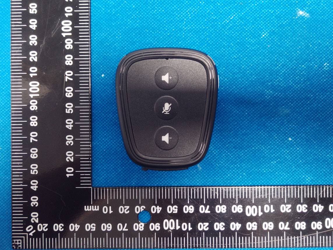
Click to zoom
Application Details
- Equipment Class
- PUT - Part 15 Unlicensed PCS portable Tx worn on body
- Date of Grant
- Feb 05, 2024
- Application Purpose
- Original Equipment
- Date of Application
- Feb 05, 2024
- Equipment Note
- CAME-NANO Wireless Intercom
- Frequency Range
- 1921.53600000 - 1928.44800000
- Country
- China
Documents & Files
Document Text
Text extracted from the exhibit documents filed with the FCC. Open a document above to read the original.
Users Manual
NANO USER MANUAL The CAME-NANO is a compact portable intercom device that adopts full duplex technology, allowing multiple parties to have simultaneous conversations. It features a built-in speaker on the fuselage, which can produce sound externally, and it can also be connected to other audio devices using a 3.5mm audio jack. It offers versatile carrying options, such as hanging, clipping, or holding it by hand. Suggestions for optimal use 1 When you receive NANO, please charge it before turning it on. Make sure the devices are in off state while charging to prevent battery draining when fully charged. When devices are in close proximity, they may generate noise. To mitigate this, press the middle button to turn off the microphone. 2 The intercom system consists of a master and multiple remotes. The master acts as a signal transfer station for the remotes. So in actual use, the remotes should be distributed around the master to achieve the optimal use effect. 3 The best communication quality is achieved when there are no obstacles between the master and remotes. Obstructions like the human body can impact the effectiveness of the device.So we advise using arm belt. 4 Some frequencies used by mobile phone signal base stations may interfere with the Nano system, causing disruptions when it is in use. 5 The signal antenna of the CAME-NANO is generally located around the lanyard hole area. It is important to not cover this region to ensure quality communication. 6 To maximize audio performance, it is recommended to use official standard headphones. The 3.5mm interface follows the OMTP standard. If you have (US) CTIA standard equipment, an audio cable will be required. CAME-NANO Portable Intercom System 1 1 2 3 4 5 6 7 8 CAME-NANO Parameters Parameters StandardDECT technology, GAP compatible Working Distance 1100 ft. radius at Master in the open air Working TimeMaster 8 Hours // Remote 15 Hours Channel Bandwidth1.728MHz Modulation TypeGFSK Duplex OperationTime Division Duplex (TDD) CE Frequency1881.792-1897.344 MHz FCC Frequency1921.536-1928.448 MHz Type-C Charging5V, 500mA Battery Capacity1100 mAh Audio Interface3.5mm TRRS (OMTP) 2 Product Structure The Master buttons are in red with the letter “M”, while the Remote buttons are in white without letters. MASTER REMOTE Microphone Power Switch / Working Indicator Volume Up Volume Down Type-C Charging Port 3.5mm Audio Jack Mute On / Off CAME-NANO 3 Back ClipSpeaker Microphone Power Switch / Working Indicator Lanyard Hole Power Switch / Working StateLED Indicator High battery levelGreen Medium battery levelYellow Low battery levelRed Mute onFlashing Mute offSolid ChargingFlashing in colours Fully chargedTurn off automatically Connected / unpairedSolid Paired but unconnectedFlashing * Make sure the devices are in off state while charging, to prevent battery draining when fully charged. CAME-NANO 4 1100ft(350m)1100ft(350m) 1100ft(350m) 1100ft(350m) 5 Person TeamMax Distance 2200ft 5 Master A A B C K J Master Remote A B C J K Pairing Diagram CAME-NANO 6 1100ft(350m) 1100ft(350m) 1100ft(350m) 1100ft(350m) Master A 7 Person Team Max Distance 2200ft 7 A M1 M2 G D H E I F HUB Master Master Master Remote Remote Remote A M1 M2 R D E F G H I Pairing Diagram CAME-NANO R 8 1100ft(350m) 1100ft(350m) 1100ft(350m) 1100ft(350m) 1100ft(350m) 1100ft(350m) 1100ft(350m) 10 Person Team Max Distance 3300ft Master A 9 B C J Pairing Diagram CAME-NANO M1 M2 R G D H E I F HUB A Master Master Master Remote Remote Remote A M1 M2 R B C J D E F G H I 10 8 Person Team CAME-NANO 8 Person Talking in One Group or Split into Two Groups (Each Group Five Person) 3.5mm Audio Cable ( Make sure connect with two different groups ) Master AMaster A 11 20 Person Team CAME-NANO 3.5mm Audio Cable ( Make sure connect with two different groups ) Master AMaster A Expanding to 20 Person Talking or Split into 2/3/4 Different Groups 12 The Hub incorporates two Masters and one built-in Remote. Each Master within the Hub can accommodate up to 3 Remotes. With this configuration, a single hub enables connections for up to 10 NANO within a single system, while two hubs can facilitate connections for up to 15 NANO. (Please refer to the pairing diagram above for further guidance.) The hub has a micro USB port to power/charge the unit via 5V DC with a USB power supply or power bank. When power is connected it can run directly without batteries and also charge when batteries are installed. The Hub can run alone on batteries and with one installed run time is about 8-10 hours and with two batteries installed, the run time increases to about 15-18 hours. INPUT OFF ON USB Function 1. Direct Power Supply to the HUB 2. Charge batteries in the battery compartment. 3.5mm TRRS audio jack It adheres to the OMTP standard. If your equipment follows the United States CTIA standard, you will need to use a conversion cable. USB 5V Switch button 3.5mm TRRS Nano with Hub Set CAME-NANO 13 Nano with Hub Set M1RemoteM2 Product details CAME-NANO 1 12 3 4 5 6 7 8 9 10 2 3 1010 6 7 8 9 4 5 Working indicator for M1 group Working indicator for HUB remote Working indicator for M2 group Master 1 button Remote buttonMaster 2 button Charging indicator Power indicator Charging indicatorBattery compartment 14 The working indicator aids in distinguishing the Master to which the remote belongs. When viewed vertically from the top, the M1 and M2 indicators display the number of remotes they are connected to, with each Master capable of connecting to up to 3 remotes. Consequently, up to 6 indicators can illuminate simultaneously. If a remote powers off or disconnects, the corresponding indicator will extinguish. For instance, if one of the remotes connected to M1 powers off, only two of M1's indicators will remain lit, while M2's indicators will remain unaffected. As long as an NB-6L battery is present in the battery compartment, it will constantly supply power to the hub. If there is no battery, the hub can also be connected to an exter…
Text truncated - open the document above for the full version.
Attestation Statements
XIAMEN CAME TECHNOLOGY CO.,LTD ADD: Unit 2204-1, NO.5 Chengyi North Street, Phase Three Software Park, Jimei District, Xiamen, 361022 China Tel: +86-592-6283638 Email: [email protected] CFR 47 §2.911(d)(5)(i) Attestation Letter Attestation Letter Date: 2023-12-29 FEDERAL COMMUNICATIONS COMMISSIONS Authorization and Evaluation Division 7435 Oakland Mills Road Columbia, MD 21046 Ref: Attestation Statements CFR 47 §2.911(d)(5)(i) Filing FCC ID:2ATOR-NANO-R XIAMEN CAME TECHNOLOGY CO.,LTDcertifies that the equipment for which authorization is soughtis not “covered” equipment prohibited from receiving an equipment authorization pursuant to section 2.903 of the FCC rules. Sincerely, Signature Contact Person:David Wang Title: Manager
Attestation Statements
XIAMEN CAME TECHNOLOGY CO.,LTD ADD: Unit 2204-1, NO.5 Chengyi North Street, Phase Three Software Park, Jimei District, Xiamen, 361022 China Tel: +86-592-6283638 Email: [email protected] CFR 47 §2.911 (d)(5)(ii) Attestation Letter Attestation Letter Date: 2023-12-29 FEDERAL COMMUNICATIONS COMMISSIONS Authorization and Evaluation Division 7435 Oakland Mills Road Columbia, MD 21046 Ref: Attestation Statements CFR 47 §2.911(d)(5)(ii) Filing FCC ID: 2ATOR-NANO-R XIAMEN CAME TECHNOLOGY CO.,LTDcertifies that as of the date of the filing of the application, the applicant is not identified on the Covered List as an entity producing “covered” equipment. Sincerely, Signature Contact Person:David Wang Title: Manager
Cover Letter(s)
XIAMEN CAME TECHNOLOGY CO.,LTD ADD: Unit 2204-1, NO.5 Chengyi North Street, Phase Three Software Park, Jimei District, Xiamen, 361022 China Tel: +86-592-6283638 Email: [email protected] QA-FR-170-B 7/29/2014 FCC Authorization Date: 2023-12-29 FEDERAL COMMUNICATIONS COMMISSIONS Authorization and Evaluation Division 7435 Oakland Mills Road Columbia, MD 21046 Subject: Agent Authorization To whom it may concern: We XIAMEN CAME TECHNOLOGY CO.,LTD, the undersigned, hereby authorizes China Certification ICT Co., Ltd (Dongguan) to act on its behalf in all matters relating to application for Equipment authorization, including the signing of all documents relating to these matters. All acts carried out by China Certification ICT Co., Ltd (Dongguan) on our behalf shall have the same effect as our own action. We, the undersigned, hereby certify that we are not subject to a denial of federal benefits, that includes FCC benefits, pursuant to Section 5301 of the Anti-Drug Abuse Act of 1988, 21 U.S.C. 862. This authorization is valid until further written notice from the applicant. Sincerely Yours, Signature: David Wang Manager
Cover Letter(s)
XIAMEN CAME TECHNOLOGY CO.,LTD ADD: Unit 2204-1, NO.5 Chengyi North Street, Phase Three Software Park, Jimei District, Xiamen, 361022 China Tel: +86-592-6283638 Email: [email protected] FCC Confidential Authorization Date: 2023-12-29 FEDERAL COMMUNICATIONS COMMISSIONS Authorization and Evaluation Division 7435 Oakland Mills Road Columbia, MD 21046 Subject: Confidentiality Request regarding application for certification of FCC ID: 2ATOR-NANO-R In accordance with Sections 0.457 and 0.459 of the Commission’s Rules, XIAMEN CAME TECHNOLOGY CO.,LTD hereby requests long-term confidential treatment of information accompanying this application as outlined below: • Block Diagram • Schematics • Operation Description The above materials contain proprietary and confidential information not customarily released to the public. The public disclosure of these materials provides unjustified benefits to its competitors in the market. Sincerely Yours, Signature: David Wang Manager
External Photos
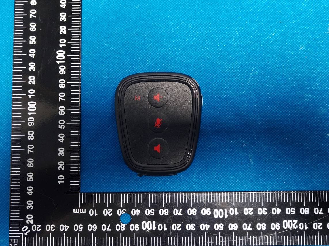
China Certification ICT Co., Ltd (Dongguan) Report No.: CR231165014-EXP EUT EXTERNAL PHOTOGRAPHS China Certification ICT Co., Ltd (Dongguan) Report No.: CR231165014-EXP China Certification ICT Co., Ltd (Dongguan) Report No.: CR231165014-EXP China Certification ICT Co., Ltd (Dongguan) Report No.: CR231165014-EXP
Internal Photos
China Certification ICT Co., Ltd (Dongguan) Report No.: CR231165014-INP EUT INTERNAL PHOTOGRAPHS China Certification ICT Co., Ltd (Dongguan) Report No.: CR231165014-INP China Certification ICT Co., Ltd (Dongguan) Report No.: CR231165014-INP China Certification ICT Co., Ltd (Dongguan) Report No.: CR231165014-INP ANT
RF Exposure Info
SAR TEST REPORT Applicant: XIAMEN CAME TECHNOLOGY CO.,LTD Address: Unit 2204-1, NO.5 Chengyi North Street, Phase Three Software Park, Jimei District, Xiamen, 361022 China FCC ID: 2ATOR-NANO-R Product Name: CAME-NANO Wireless Intercom Model Number: CAME-NANO Multiple Models: N/A Standard(s): 47 CFR Part 2(2.1093) The above device has been tested and found compliant with the requirement of the relative standards by China Certification ICT Co., Ltd (Dongguan) Report Number: CR231165014-SA Date Of Issue: 2023-12-17 Reviewed By: Karl Gong Title: SAR Engineer Test Laboratory: China Certification ICT Co., Ltd (Dongguan) No. 113, Pingkang Road, Dalang Town, Dongguan, Guangdong, China Tel: +86-769-82016888 China Certification ICT Co., Ltd (Dongguan) Report No.: CR231165014-SA Page 2 of 56 SAR TEST RESULTS SUMMARY Operation Frequency Bands Highest Reported 1g SAR (W/kg) Limits (W/kg) Body SAR (Gap 0mm) DECT 0.11 1.6 EUT Received Date: 2023/11/06 Tested Date: 2023/12/01 Tested Result: Pass China Certification ICT Co., Ltd (Dongguan) Report No.: CR231165014-SA Page 3 of 56 Test Facility The Test site used by China Certification ICT Co., Ltd (Dongguan) to collect test data is located on the No. 113, Pingkang Road, Dalang Town, Dongguan, Guangdong, China. The lab has been recognized as the FCC accredited lab under the KDB 974614 D01 and is listed in the FCC Public Access Link (PAL) database, FCC Registration No. : 442868, the FCC Designation No. : CN1314. The lab has been recognized by Innovation, Science and Economic Development Canada to test to Canadian radio equipment requirements, the CAB identifier: CN0123. Declarations China Certification ICT Co., Ltd (Dongguan) is not responsible for the authenticity of any test data provided by the applicant. Data included from the applicant that may affect test results are marked with a triangle symbol “▲”. Customer model name, addresses, names, trademarks etc. are not considered data. Unless otherwise stated the results shown in this test report refer only to the sample(s) tested. This report cannot be reproduced except in full, without prior written approval of the Company. This report is valid only with a valid digital signature. The digital signature may be available only under the Adobe software above version 7.0. This report may contain data that are not covered by the accreditation scope and shall be marked with an asterisk “★”. China Certification ICT Co., Ltd (Dongguan) Report No.: CR231165014-SA Page 4 of 56 CONTENTS DOCUMENT REVISION HISTORY .......................................................................................... 6 1. GENERAL INFORMATION .................................................................................................... 7 1.1 PRODUCT DESCRIPTION FOR EQUIPMENT UNDER TEST (EUT) ....................................................... 7 1.2 TEST SPECIFICATION, METHODS AND PROCEDURES ........................................................................ 8 1.3 SAR LIMITS .......................................................................................................................................... 9 1.4 FACILITIES ...................................................................................................................................... 10 2. SAR MEASUREMENT SYSTEM .......................................................................................... 11 3. EQUIPMENT LIST AND CALIBRATION .......................................................................... 18 3.1 EQUIPMENTS LIST & CALIBRATION INFORMATION ....................................................................... 18 4. SAR MEASUREMENT SYSTEM VERIFICATION ........................................................... 19 4.1 LIQUID VERIFICATION ...................................................................................................................... 19 4.2 SYSTEM ACCURACY VERIFICATION ................................................................................................. 20 4.3 SAR SYSTEM VALIDATION DATA ............................................................................................. 21 5. EUT TEST STRATEGY AND METHODOLOGY .............................................................. 22 5.1 TEST POSITIONS FOR BODY-WORN AND OTHER CONFIGURATIONS ................................................ 22 5.2 TEST DISTANCE FOR SAR EVALUATION .......................................................................................... 22 5.3 SAR EVALUATION PROCEDURE ....................................................................................................... 23 6. CONDUCTED OUTPUT POWER MEASUREMENT ........................................................ 24 6.1 TEST PROCEDURE .............................................................................................................................. 24 6.2 MAXIMUM TARGET OUTPUT POWER ............................................................................................... 24 6.3 TEST RESULTS: .................................................................................................................................. 24 7. Standalone SAR test exclusion considerations ....................................................................... 26 7.1 ANTENNA DISTANCE TO EDGE ......................................................................................................... 26 7.2 STANDALONE SAR TEST EXCLUSION CONSIDERATIONS ................................................................. 26 7.3 STANDALONE SAR TEST EXCLUSION CONSIDERATIONS: ................................................................ 27 7.4 SAR TEST EXCLUSION FOR THE EUT EDGE CONSIDERATIONS RESULT ........................................ 27 SAR TEST EXCLUSION FOR THE EUT EDGE CONSIDERATIONS DETAIL: ............................................. 27 8. SAR MEASUREMENT RESULTS ........................................................................................ 28 8.1 SAR…
Text truncated - open the document above for the full version.
Test Report
1 CORPORATENAME :S HENZHENDEXUNPRECISION E LECTRONICS C O .L ADDRESS :5/F, BUILDINGE ,H ONGYUAN I NDUSTRIAL Z ONE ,H UACHANG R OAD ,D ALANGSTREET , L ONGHUA D ISTRICT ,S HENZHEN 1 深圳德勋精密电子有限公司 ShenzhendexunprecisionElectronicsCo.L Productspecifications ProductName:1.9GhzAntenna 2 CORPORATENAME :S HENZHENDEXUNPRECISION E LECTRONICS C O .L ADDRESS :5/F, BUILDINGE ,H ONGYUAN I NDUSTRIAL Z ONE ,H UACHANG R OAD ,D ALANGSTREET , L ONGHUA D ISTRICT ,S HENZHEN 2 一、Productstructurediagram 3 CORPORATENAME :S HENZHENDEXUNPRECISION E LECTRONICS C O .L ADDRESS :5/F, BUILDINGE ,H ONGYUAN I NDUSTRIAL Z ONE ,H UACHANG R OAD ,D ALANGSTREET , L ONGHUA D ISTRICT ,S HENZHEN 3 二、Passivestandingwave 190041.20% 191041.80% 192046.00% 193042.30% 194048.30% 195051.20% 196049.10% 197057.90% 198055.80% 199057.10% 200061.10% Antennastandingwave Passivegainefficiency Frequency Gain Efficiency 0.5 -0.3 0 -0.2 0.1 0.3 -0.1 0.6 0.5 0.8 1.4 (MHz) (dBi) 4 CORPORATENAME :S HENZHENDEXUNPRECISION E LECTRONICS C O .L ADDRESS :5/F, BUILDINGE ,H ONGYUAN I NDUSTRIAL Z ONE ,H UACHANG R OAD ,D ALANGSTREET , L ONGHUA D ISTRICT ,S HENZHEN 4 三、3DImage 3DImage
Test Report
TEST REPORT Applicant: XIAMEN CAME TECHNOLOGY CO.,LTD Address: Unit 2204-1, NO.5 Chengyi North Street, Phase Three Software Park, Jimei District, Xiamen, 361022 China FCC ID: 2ATOR-NANO-R Product Name: CAME-NANO Wireless Intercom Standard(s): FCC PART 15D ANSI C63.17-2013 The above device has been tested and found compliant with the requirement of the relative standards by China Certification ICT Co., Ltd (Dongguan) Report Number: CR231165014-00 Date Of Issue: 2023/12/6 Reviewed By: Calvin Chen Title: RF Engineer Approved By: Sun Zhong Title: Manager Test Laboratory: China Certification ICT Co., Ltd (Dongguan) No. 113, Pingkang Road, Dalang Town, Dongguan, Guangdong, China Tel: +86-769-82016888 China Certification ICT Co., Ltd (Dongguan) Report No.: CR231165014-00 Page 2 of 50 Test Facility The Test site used by China Certification ICT Co., Ltd (Dongguan) to collect test data is located on the No. 113, Pingkang Road, Dalang Town, Dongguan, Guangdong, China. The lab has been recognized as the FCC accredited lab under the KDB 974614 D01 and is listed in the FCC Public Access Link (PAL) database, FCC Registration No. : 442868, the FCC Designation No. : CN1314. The lab has been recognized by Innovation, Science and Economic Development Canada to test to Canadian radio equipment requirements, the CAB identifier: CN0123. Declarations China Certification ICT Co., Ltd (Dongguan) is not responsible for the authenticity of any test data provided by the applicant. Data included from the applicant that may affect test results are marked with a triangle symbol “▲”. Customer model name, addresses, names, trademarks etc. are not considered data. Unless otherwise stated the results shown in this test report refer only to the sample(s) tested. This report cannot be reproduced except in full, without prior written approval of the Company. This report is valid only with a valid digital signature. The digital signature may be available only under the Adobe software above version 7.0. This report may contain data that are not covered by the accreditation scope and shall be marked with an asterisk “★”. China Certification ICT Co., Ltd (Dongguan) Report No.: CR231165014-00 Page 3 of 50 CONTENTS DOCUMENT REVISION HISTORY .......................................................................................... 5 1. GENERAL INFORMATION .................................................................................................... 6 1.1 PRODUCT DESCRIPTION FOR EQUIPMENT UNDER TEST (EUT) ....................................................... 6 1.2 DESCRIPTION OF TEST CONFIGURATION ........................................................................................... 7 1.2.1 EUT Operation Condition: ............................................................................................................................. 7 1.2.2 Support Equipment List and Details .............................................................................................................. 7 1.2.3 Support Cable List and Details ...................................................................................................................... 7 1.2.4 Block Diagram of Test Setup ......................................................................................................................... 7 1.3 MEASUREMENT UNCERTAINTY .......................................................................................................... 8 2. SUMMARY OF TEST RESULTS ............................................................................................ 9 3. REQUIREMENTS AND TEST PROCEDURES .................................................................. 10 3.1 CONDUCTED EMISSIONS .................................................................................................................... 10 3.1.1 Applicable Standard ..................................................................................................................................... 10 3.1.2 EUT Setup.................................................................................................................................................... 10 3.1.3 EMI Test Receiver Setup ............................................................................................................................. 10 3.1.4 Test Procedure ............................................................................................................................................. 11 3.1.5 Corrected Amplitude & Margin Calculation ................................................................................................ 11 3.2 EMISSION BANDWIDTH: .................................................................................................................... 12 3.2.1 Applicable Standard ..................................................................................................................................... 12 3.2.2 EUT Setup.................................................................................................................................................... 12 3.2.3 Test Procedure ............................................................................................................................................. 12 3.3 PEAK TRANSMIT POWER: ................................................................................................................. 13 3.3.1 Applicable Standard ..................................................................................................................................... 13 3.3.2 EUT Setup.................................................................................................................................................... 13 3.3.3 Test Procedure ............................................................................................................................................. 13 3.4 POWER SPECTRAL DENSITY: .....................................................…
Text truncated - open the document above for the full version.
Test Setup Photos
China Certification ICT Co., Ltd (Dongguan) Report No.: CR231165014-00-TSP TEST SETUP PHOTOGRAPHS Conducted Emissions Front View Conducted Emissions Side View
Contact Information
Applicant
David Wang(Manager)
Test Firm
CHINA CERTIFICATION ICT CO., LTD (DONGGUAN)Tanie Ou
[email protected]0086 0769 86858888
Technical Specifications
| # | Rule Parts | Frequency Range | Power Output |
|---|---|---|---|
| 1 | 15D | 1.92 GHz - 1.93 GHz | 74.00 mW |
Other Applications from XIAMEN CAME TECHNOLOGY CO.,LTD
2ATOR-NANO-M
Feb 05, 2024CAME-NANO Wireless Intercom
Equipment Class
PUT - Part 15 Unlicensed PCS portable Tx worn on body2ATOR-KUMINIK8-2R
Jul 25, 2022Wireless Headsets
Equipment Class
PUE - Part 15 Unlicensed PCS portable Tx held to ear