2ATPO-TB-02Bluetooth module
Shenzhen Ai-Thinker Technology Co., Ltd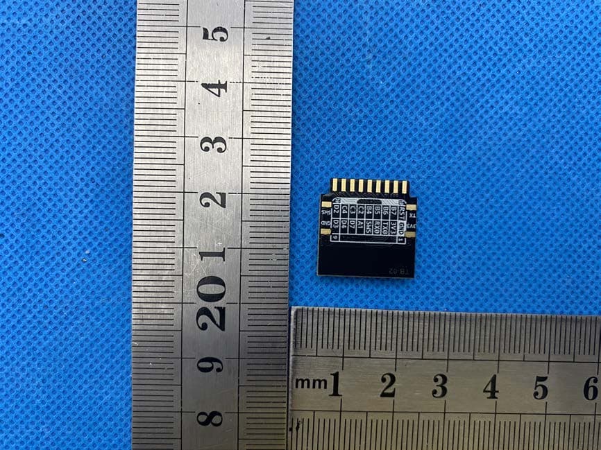
Click to zoom
Application Details
- Equipment Class
- DTS - Digital Transmission System
- Date of Grant
- Mar 16, 2020
- Application Purpose
- Original Equipment
- Date of Application
- Mar 16, 2020
- Equipment Note
- Bluetooth module
- Frequency Range
- 2402.00000000 - 2480.00000000
- Country
- China
Documents & Files
Document Text
Text extracted from the exhibit documents filed with the FCC. Open a document above to read the original.
Users Manual
TB-02 Specification V1.0 Copyright © 2019 Shenzhen Ai-Thinker Technology Co., Ltd All Rights Reserved I TB-02 Specification Version V1.0 Copyright ©2019 TB-02 Specification V1.0 Copyright © 2019 Shenzhen Ai-Thinker Technology Co., Ltd All Rights Reserved II Disclaimer and Copyright Notice The information in this article, including URL addresses for reference, is subject to change without notice. This document is provided "as is" without warranty of any kind, including any warranty of merchantability, fitness for a particular purpose, or non-infringement, and any warranty of any proposal, specification, or sample mentioned elsewhere. No liability is assumed in this document, including any infringement of any patent rights arising out of the use of the information in this document. No license is granted by estoppel or otherwise in this document, either express or implied. The test data obtained in this article are all obtained from the testing performed by Anxinke Labs. Actual results may vary slightly. The Bluetooth Alliance member logo is owned by the Bluetooth Alliance. All trademark names, trademarks and registered trademarks mentioned in this article are the property of their respective owners and are hereby declared. The final interpretation right belongs to Shenzhen Anxinke Technology Co., Ltd. Pay attention The contents of this manual may be changed due to product version upgrades or other reasons. Shenzhen Anxinke Technology Co., Ltd. reserves the right to modify the contents of this manual without any notice or prompt. This manual is only used as a guide. Shenzhen Anxin Ke Technology Co., Ltd. makes every effort to provide accurate information in this manual, but Shenzhen An Xin Ke Technology Co., Ltd. does not ensure that the content of the manual is completely error-free. All statements and information in this manual And recommendations do not constitute any express or implied warranty. TB-02 Specification V1.0 Copyright © 2019 Shenzhen Ai-Thinker Technology Co., Ltd All Rights Reserved III Document development/revision/revocation resume Version Date Revised content Maker Approve V1.0 2019.11.25 First developed Yiji Xie TB-02 Specification V1.0 Copyright © 2019 Shenzhen Ai-Thinker Technology Co., Ltd All Rights Reserved IV CONTENT 1.INTRODUCTION .............................................................................................................................................. V 2.SPECIFICATION .............................................................................................................................................. VII 3.DIMENSION ................................................................................................................................................. VIII 4.PIN DEFINITION ............................................................................................................................................. IX 5.SCHEMATIC .................................................................................................................................................... XI 6.DESIGN GUIDE ............................................................................................................................................... XI 7.REFLOW PROFILE ......................................................................................................................................... XIV 8.PACKAGING .................................................................................................................................................. IXV 9.CONTACT US ................................................................................................................................................ IXV TB-02 Specification V1.0 Copyright © 2019 Shenzhen Ai-Thinker Technology Co., Ltd All Rights Reserved V 1.INTRODUCTION The TB-02 intelligent lighting module is a Bluetooth module based on the TLSR8250F512 chip and compatible with BT 5.0 low-power Tmall Genie Mesh. This module supports the Bluetooth module directly controlled by Tmall Genie and has a Bluetooth mesh networking function. Peer-to-peer network communication, using Bluetooth broadcast for communication, can ensure timely response in the case of multiple devices. It is mainly used in intelligent light control, which can meet the requirements of low power consumption, low latency, and short-range wireless data communication. Features Can be directly controlled by Tmall Elf without a gateway 1.6mm pitch pin vertical solder DIP18 package 6 PWM outputs With on-board antenna, no need to design antenna Brightness (duty cycle) adjustment range 5% -100% Factory default 50% duty cycle for cool and warm colors PWM output power 1KHz With night light function With wall switch to switch color temperature function TB-02 Specification V1.0 Copyright © 2019 Shenzhen Ai-Thinker Technology Co., Ltd All Rights Reserved VI LIST 1 Main Parameters Model Name TB-02 Size 18.0*18.0*2.8(±0.2)MM Wireless Standard Bluetooth V5.0 Frequency Range 2402 ~ 2480MHz Max Sensitivity -93.2dBm Interface GPIO/PWM/SPI/ADC Work Temperature -20°C ~ 70 °C Store Temperature -40 °C ~ 125 °C , < 90%RH Voltage Range Voltage 2.7V ~ 3.6V, Current≥50mA Power Deep Sleep Mode:0.8uA Sleep Mode:1.8uA TX:12.62mA Transmission distance 80m ~ 150m TB-02 Specification V1.0 Copyright © 2019 Shenzhen Ai-Thinker Technology Co., Ltd All Rights Reserved VII 2.SPECIFICATION Electrical characteristics Absolute Maximum Rating Any exceeding the following absolute maximum ratings may cause damage to TLSR8250F512 RF Specification Sensitivity Item Min Typical Max Unit Sensitivity -92dBm-91dBm-90dBm dBm Item Min Typical Max Unit Voltage 2.7 3.3 3.6 V I/O Voltage (VCCIO) -0.3- 3.6 V Work Temperature -20- +70 °C Store Temperature -40- +125 °C TB-02 Specification V1.0 Copyright © 2019 Shenzhen Ai-Thinker Technology Co., Ltd All Rights Reserved VIII 3.DIMENSION TB-02 Specification V1.0 Copyright © 2019 Shenzhen Ai-Thinker Techn…
Text truncated - open the document above for the full version.
Cover Letter(s)
Date: Mar. 13, 2020 Equipment Autorisation Division Federal Communications Commission 7435 Oakland Mills Road Columbia, MD 21046 FCC ID: 2ATPO-TB-02 Product Name: Bluetooth module Request for Confidentiality Pursuant to Sections 0.457 and 0.459 of the commission’s rules, we hereby request that the following documents be held confidential: (List here the documents for which you are seeking confidentiality – for example ...) • Schematics • Block diagram • Operation description These materials contain trade secrets and proprietary information and are not customarily released to the public. The public disclosure of this information might be harmful to the company and provide unjustified benefits to our competitors. <Signature> Name: Su Facheng Title: Engineer Company: Shenzhen Ai-Thinker Technology Co., Ltd
Cover Letter(s)
Date: Mar. 13, 2020 Federal Communications Commission Authorization & Evaluation Division 7345 Oakland Mills Road Columbia, Maryland 21046 Authority to Act as Agent On our behalf, I appoint Shenzhen CTB Testing Technology Co., Ltd. Add: Floor 1&2, Building A, No. 26 of Xinhe Road, Xinqiao Community, Xinqiao Street, Baoan District, Shenzhen, Guangdong, China to act as our agent in the preparation of this application for equipment certification. I certify that submitted documents properly describe the device or system for which equipment certification is sought. I also certify that each unit manufactured, imported or marketed, as defined in the Federal Communications Commission’s regulations will have affixed to it a label identical to that submitted for approval with this application. For instances where our authorized agent signs the application for certification on our behalf, I acknowledge that all responsibility for complying with the terms and conditions for certification, still resides with Shenzhen Ai-Thinker Technology Co., Ltd Add: Room 701, Building B, Huafeng Industrial Park, Hangkong Road, Sanwei Community, Baoan District, Shenzhen China <Signature> Name: Su Facheng Title: Engineer Company: Shenzhen Ai-Thinker Technology Co., Ltd
Cover Letter(s)
Single Modular approval Declaration letter We, Shenzhen Ai-Thinker Technology Co., Ltd apply Single modular approval for Product Name: Bluetooth module MODEL No.: TB-02 FCC ID: 2ATPO-TB-02 According to 996369 D01 Module Equip Auth Guide v01r04 and 15.212 requirement: 1)The radio elements must have the radio frequency circuitry shielded. Physical components and tuning capacitor(s) may be located external to the shield, but must beon the module assembly; Answer :Yes,both side shielded 2)The module must have buffered modulation/data inputs to ensure that the device will comply with Part 15 requirements with any type of input signal; Answer :Yes ;All inputs to the modules are buffered through logic or microprocessor inputs. 3)The modular transmitter must have its own power supply regulation. A nswer :Yes ;A low drop out regulator is used for modular power supply regulation. 4)The module must contain a permanently attached antenna, or contain a unique antenna connector, and be marketed and operated only with specific antenna(s), per Sections 15.203, 15.204(b), 15.204(c), 15.212(a), 2.929(b); Answer :Yes ;Device is equipped with Integral PCB antenna. (5)The module must demonstrate compliance in a stand-alone configuration; Answer :Yes,distance between modular and all AEs are longer than 10cm ,refer to setup photo. ( 6)The module must be labelled with its permanently affixed FCC ID label, or use an electronic display (See KDB Publication 784748 about labelling requirements); Answer :Yes ;The modular has a permanent fixed label, and below statement was listed in the User Manual;The host device must be labeled to display the FCC ID of the module Contains FCC ID: 2ATPO-TB-02 (7)The module must comply with all specific rules applicable to the transmitter including all the conditions provided in the integration instructions by the grantee; Answer :Yes ;The module comply with all specific rules applicable to the transmitter including all the conditions provided in the integration instructions by the grantee, Refer to test report and user manual . (8)The module must comply with RF exposure requirements Answer :Yes ;Transmitter meets MPE calculation of 47 CFR 1.1307 . Refer to MPE R eports and Refer to modular installation manual < Signature> Nam e: Su Facheng Title: Engineer Company: Shenzhen Ai-Thinker Technology Co., Ltd
Cover Letter(s)
Compliance list INTEGRATION INSTRUCTIONS for 996369 D03 OEM the and 996369 D03 OEM by Sections 2.2 through 2.10. Requirement Yes N/A Comment 2.2 List of applicable FCC rules List the FCC rules that are applicable to the modular transmitter. These are the rules that specifically establish the bands of operation, the power, spurious emissions, and operating fundamental frequencies. DO NOT list compliance to unintentional-radiator rules (Part 15 Subpart B) since that is not a condition of a module grant that is extended to a host manufacturer. See also Section 2.10 below concerning the need to notify host manufacturers that further testing is required.3 YES Refer to instruction FCC stan dards: FCC CFR Title 47 Part 15 Subpart C Section 15.247 2.3 Summarize the specific operational use conditions Describe use conditions that are applicable to the modular transmitter, including for example any limits on antennas, etc. For example, if point-to-point antennas are used that require reduction in power or compensation for cable loss, then this information must be in the instructions. If the use condition limitations extend to professional users, then instructions must state that this information also extends to the host manufacturer’s instruction manual. In addition, certain information may also be needed, such as peak gain per frequency band and minimum gain, specifically for master devices in 5 GHz DFS bands. YES Refer to instruction PCB an tenna; Antenna gain: 2 dBi 2.4 Limited module procedures If a modular transmitter is approved as a “limited module,” then the module manufacturer is responsible for approving the host environment that the limited module is used with. The manufacturer of a limited module must describe, both in the filing and in the installation instructions, the alternative means that the limited module manufacturer uses to verify that the host meets the necessary requirements to satisfy the module limiting conditions. A limited module manufacturer has the flexibility to define its alternative method to address the conditions that limit the initial N /A Not applicable approval, such as: shielding, minimum signaling amplitude, buffered modulation/data inputs, or power supply regulation. The alternative method could include that the limited module manufacturer reviews detailed test data or host designs prior to giving the host manufacturer approval. This limited module procedure is also applicable for RF exposure evaluation when it is necessary to demonstrate compliance in a specific host. The module manufacturer must state how control of the product into which the modular transmitter will be installed will be maintained such that full compliance of the product is always ensured. For additional hosts other than the specific host originally granted with a limited module, a Class II permissive change is required on the module grant to register the additional host as a specific host also approved with the module. 2.5 Trace antenna designs For a modular transmitter with trace antenna designs, see the guidance in Question 11 of KDB Publication 996369 D02 FAQ – Modules for Micro-Strip Antennas and traces. The integration information shall include for the TCB review the integration instructions for the following aspects: layout of trace design, parts list (BOM), antenna, connectors, and isolation requirements.4 a) Information that includes permitted variances (e.g., trace boundary limits, thickness, length, width, shape(s), dielectric constant, and impedance as applicable for each type of antenna); b) Each design shall be considered a different type (e.g., antenna length in multiple(s) of frequency, the wavelength, and antenna shape (traces in phase) can affect antenna gain and must be considered); c) The parameters shall be provided in a manner permitting host manufacturers to design the printed circuit (PC) board layout; d) Appropriate parts by manufacturer N/A Not applicable and specifications; e)Test procedures for design verification; and f) P roduction test procedures for ensuring compliance. The module grantee shall provide a notice that any deviation(s) from the defined parameters of the antenna trace, as described by the instructions, require that the host product manufacturer must notify the module grantee that they wish to change the antenna trace design. In this case, a Class II permissive change application is required to be filed by the grantee, or the host manufacturer can take responsibility through the change in FCC ID (new application) procedure followed by a Class II permissive change application. 2.6 RF exposure considerations It is essential for module grantees to clearly and explicitly state the RF exposure conditions that permit a host product manufacturer to use the module. Two types of instructions are required for RF exposure information: (1) to the host product manufacturer, to define the application conditions (mobile, portable – xx cm from a person’s body); and (2) additional text needed for the host product manufacturer to provide to end users in their end-product manuals. If RF exposure statements and use conditions are not provided, then the host product manufacturer is required to take responsibility of the module through a change in FCC ID (new application). YES Refer to instruction This modular complies with FCC RF radiation exposure limits set forth for an uncontrolled environment. This transmitter must not be co- located or operating in conjunction with any other antenna or transmitter. 2.7 Antennas A list of antennas included in the application for certification must be provided in the instructions. For modular transmitters approved as limited modules, all applicable professional installer instructions must be included as part of the information to the host product manufacturer. The antenna list shall also identify the antenna types (monopole, PIFA, dipole, etc. (note that for example an “omni-directional antenna” is not considered YES Refer to ins…
Text truncated - open the document above for the full version.
External Photos
M/N: TB-02 M/N: TB-02 M/N: TB-02
ID Label/Location Info
FCC ID LABEL: L abel Location: FCC ID: 2A TPO-TB-02 Long:0.8cm Width:0.2cm
Internal Photos
M/N: TB-02 PCB A N T.
RF Exposure Info
RF EXPOSURE EVALUATION 1. Standard Requirement According to KDB447498D01 General RF Exposure Guidance v06 Standalone SAR test exclusion considerations Unless specifically required by the published RF exposure KDB procedures, standalone 1- g head or body and 10-g extremity SAR evaluation for general population exposure conditions, by measurement or numerical simulation, is not required when the corresponding SAR Exclusion Threshold condition, listed below, is satisfied. 2. Limits The 1-g and 10-g SAR test exclusion thresholds for 100 MHz to 6 GHz at test separation distances ≤ 50 mm are determined by: [(max. power of channel, including tune-up tolerance, mW)/(min. test separation distance, mm)] .[√f(GHz)] ≤ 3.0 for 1-g SAR and ≤ 7.5 for 10-g extremity SAR, where • f(GHz) is the RF channel transmit frequency in GHz • Power and distance are rounded to the nearest mW and mm before calculation • The result is rounded to one decimal place for comparison • 3.0 and 7.5 are referred to as the numeric thresholds in the step2 below The test exclusions are applicable only when the minimum test separation distance is ≤ 50 mm and for transmission frequencies between 100 MHz and 6 GHz. When the minimum test separation distance is < 5 mm, a distance of 5 mm is applied to determine SAR test exclusion. 3. Test Result The max conducted power including tune-up tolerance is -0.147dBm (0.967mW). [(max.power of channel, mw)/(min. test separation distance, mm)][ √f(GHz)] =0.967/5*(√2.480)=0.3<3.0 Then SAR evaluation is not required
Test Report
Shenzhen CTB Testing Technology Co., Ltd. Report No.: CTB200305017RFX TEST REPORT Compiled by: Reviewed by: Approved by: Victory Rita Xiao Sherwin Qian/ Director The test report is effective only with both signature and specialized stamp. This result(s) shown in this report refer only to the sample(s) tested. Without written approval of Shenzhen HUAK Testing Technology Co., Ltd. this report can’t be reproduced except in full. The tested sample(s) and the sample information are provided by the client. Product Name: Bluetooth module FCC ID: 2ATPO-TB-02 Trademark: Model Number: TB-02 Prepared For: Shenzhen Ai-Thinker Technology Co., Ltd Address: Room 701, Building B, Huafeng Industrial Park, Hangkong Road, Sanwei Community, Baoan District, Shenzhen China Manufacturer: Shenzhen Ai-Thinker Technology Co., Ltd Address: Room 701, Building B, Huafeng Industrial Park, Hangkong Road, Sanwei Community, Baoan District, Shenzhen China Prepared By: Shenzhen CTB Testing Technology Co., Ltd. Address: Floor 1&2, Building A, No. 26 of Xinhe Road, Xinqiao Street, Baoan District, Shenzhen China Sample Received Date: Mar. 2, 2020 Sample tested Date: Mar. 2, 2020 to Mar. 6, 2020 Issue Date: Mar. 6, 2020 Report No.: CTB200305017RFX Test Standards FCC Part15.247 ANSI C63.10:2013 Test Results PASS Remark: This is Bluetooth radio test report. Report Tel: 4008-258-120 Web: http://www.ctb-lab.com Page 1 of 36 Shenzhen CTB Testing Technology Co., Ltd. Report No.: CTB200305017RFX TABLE OF CONTENT Test Report Declaration Page 1. VERSION ............................................................................................................ 4 2. TEST SUMMARY ............................................................................................... 5 3. MEASUREMENT UNCERTAINTY ...................................................................... 6 4. PRODUCT INFORMATION AND TEST SETUP ................................................. 7 4.1 Product Information .............................................................................................. 7 4.2 Test Setup Configuration ...................................................................................... 7 4.3 Support Equipment ............................................................................................... 7 4.4 Channel List .......................................................................................................... 8 4.5 Test Mode ............................................................................................................. 8 4.6 Test Environment .................................................................................................. 8 5. TEST FACILITY AND TEST INSTRUMENT USED ............................................. 9 5.1 Test Facility .......................................................................................................... 9 5.2 Test Instrument Used ........................................................................................... 9 6. AC POWER LINE CONDUCTED EMISSION ..................................................... 11 6.1 Block Diagram Of Test Setup ............................................................................. 11 6.2 Limit .................................................................................................................... 11 6.3 Test procedure.................................................................................................... 11 6.4 Test Result ......................................................................................................... 13 7. RADIATED SPURIOUS EMISSION .................................................................. 15 7.1 Block Diagram Of Test Setup ............................................................................. 15 7.2 Limit .................................................................................................................... 15 7.3 Test procedure.................................................................................................... 16 7.4 Test Result ......................................................................................................... 17 8. BAND EDGE AND RF COUNDUCTED SPURIOUS EMISSIONS ..................... 24 8.1 Block Diagram Of Test Setup ............................................................................. 24 8.2 Limit .................................................................................................................... 24 8.3 Test procedure.................................................................................................... 24 8.4 Test Result ......................................................................................................... 25 9. COUDUCTED PEAK OUTPUT POWER ........................................................... 27 9.1 Block Diagram Of Test Setup ............................................................................. 27 Report Tel: 4008-258-120 Web: http://www.ctb-lab.com Page 2 of 36 Shenzhen CTB Testing Technology Co., Ltd. Report No.: CTB200305017RFX 9.2 Limit .................................................................................................................... 27 9.3 Test procedure.................................................................................................... 27 9.4 Test Result ......................................................................................................... 28 10. 6DB OCCUPIED BANDWIDTH ........................................................................ 30 10.1 Block Diagram Of Test Setup ........................................................................... 30 10.2 Limit .................................................................................................................. 30 10.3 Test procedure .................................................................................................. 30 10.4 Test Result............................................…
Text truncated - open the document above for the full version.
Test Setup Photos
M/N: TB-02 Radiated Emission test M/N: TB-02 Conducted Emission test
Contact Information
Applicant
guan ning
Test Firm
Shenzhen CTB Testing Technology Co., Ltd.Rita Xiao
[email protected]86-13538218145
Technical Specifications
| # | Rule Parts | Frequency Range | Power Output |
|---|---|---|---|
| 1 | 15C | 2.40 GHz - 2.48 GHz | 966.70 µW |
Other Applications from Shenzhen Ai-Thinker Technology Co., Ltd
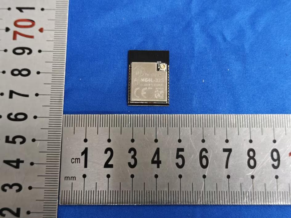
2ATPO-M64L32S
Aug 24, 2026Wi-Fi + BT Module
Equipment Class
DTS - Digital Transmission System
2ATPO-RA20
Jul 29, 2026LoRa Module
Equipment Class
DSC - Part 15 Security/Remote Control Transmitter
2ATPO-MW4N
Jul 16, 2026Wi-Fi + BT Module
Equipment Class
DTS - Digital Transmission System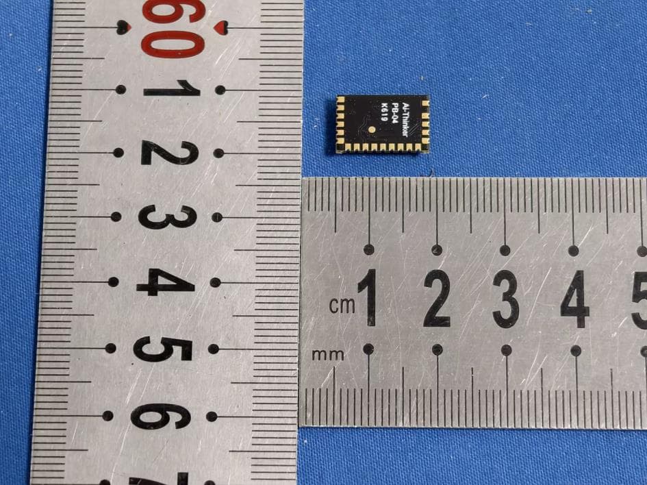
2ATPO-PB04
Jul 14, 2026BT Module
Equipment Class
DTS - Digital Transmission System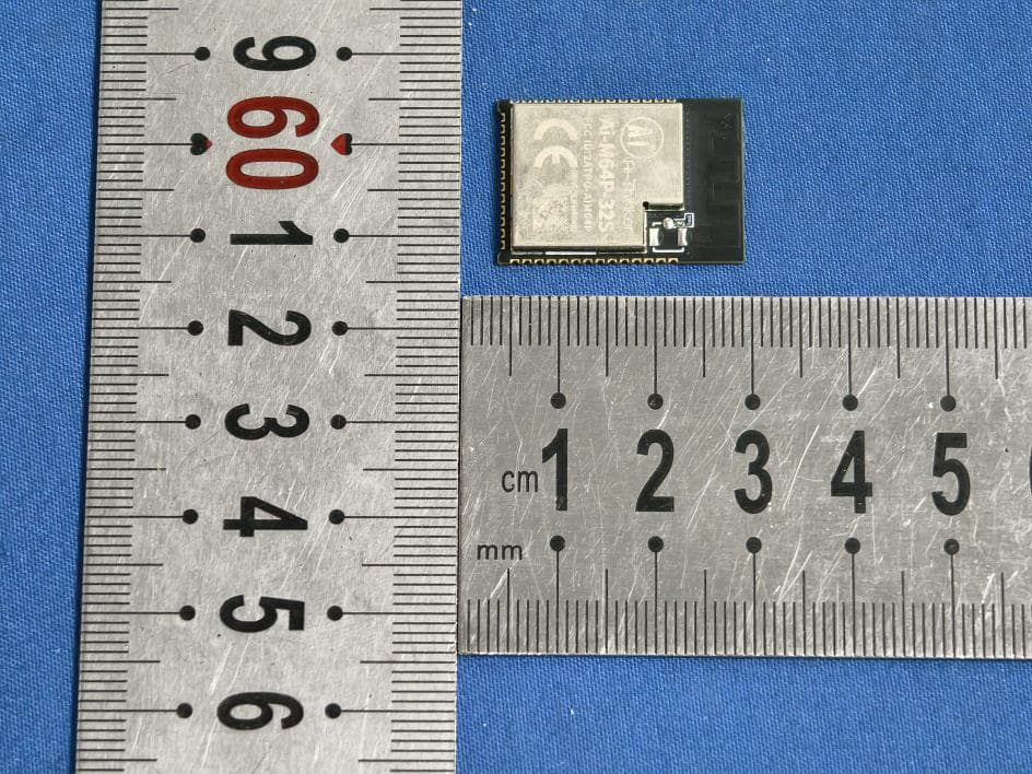
2ATPO-AIM64P
Jul 09, 2026Wi-Fi + BT Module
Equipment Class
DTS - Digital Transmission System