2ATQRSMO5GV1SkydioLink 5GHz Radio
Skydio, Inc.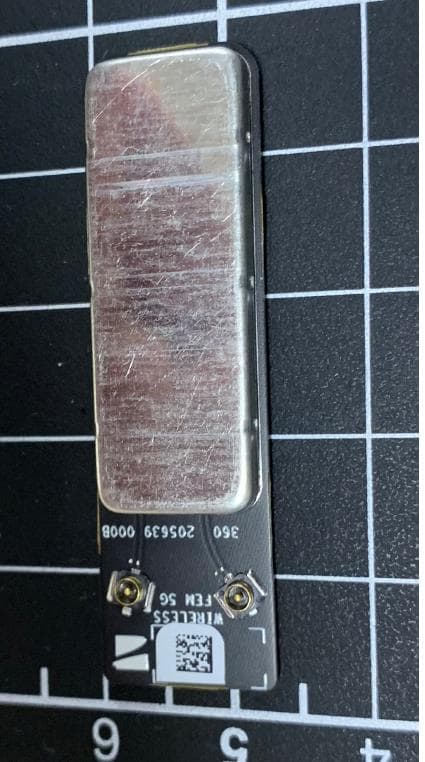
Click to zoom
Application Details
- Equipment Class
- NII - Unlicensed National Information Infrastructure TX
- Date of Grant
- Apr 13, 2021
- Application Purpose
- Original Equipment
- Date of Application
- Apr 08, 2021
- Equipment Note
- SkydioLink 5GHz Radio
- Frequency Range
- 5745.00000000 - 5825.00000000
- Company
- Skydio, Inc.
- Country
- United States
Documents & Files
Document Text
Text extracted from the exhibit documents filed with the FCC. Open a document above to read the original.
Users Manual
SkydioLink 5GHz Radio User Manual version 1.0 (2021/03/16) Table of Contents Table of Contents2 Overview3 Module Integration3 Pinout & power requirements3 Boot Sequence4 Module Mechanical Integration4 Antenna Connectors5 Thermal Management5 Usage Guidelines6 Regional Settings6 Mechanical Requirements6 Compliance Information7 Overview This document provides integration, installation and usage instructions for the SkydioLink 5GHz Radio (FCC 2ATQRSMO5GV1 / IC 25280-SMO5GV1). Module Integration Pinout & power requirements All module power and control signals are passed from the end device to the module over J9800, following the below pinout: Detail on pin-out requirements: Pin Number Required Signal Purpose 1, 3, 5, 7 5V (780 mA minimum) 5V Supply for RF front end modules 2, 4, 6, 8 3.3V 3.3V Supply for Switcher & QCA617A 9 Unused GPIO 10 1.8V Supply for QCA6174A 21 Unused GPIO 25 Unused GPIO 27 SDIO Data (0) from Host to WiFi 29 SDIO Data (1)) from Host to WiFi 31 SDIO Command from Host to WiFi 32 SDIO Data (2) from Host to WiFi 33 WiFi enable signal from Host 34 SDIO Data (3) from Host to WiFi 35 - test point 36 SDIO Clock from Host to WiFi 11 - 20, 23, 23, 26, 28, 30, 37 - 40 - Ground Boot Sequence When first turning on the radio, the below power on sequence must be used to ensure that the radio will operate correctly: Module Mechanical Integration The SkydioLink 5GHz Radio snaps into place using the two board to board connectors (Hirose DF30FC-40DP-0.4V) on the lower side of the module. All power and signal lines are passed via J9800, and J9801 is only used to secure the module in place instead of using screws. When installing the module, it is important to ensure that the technician using ESD protection On the end device, the spacing and board to board MPN must match the module side specifications: Mating board to board type: DF30FC-40DS-0.4V Mating Board to board spacing: 38.44mm, Antenna Connectors The radio module uses two I-PEX u.FL connectors (20441-001E-01) to connect external antennas to the module. The connectors are snapped an place, and do not require any external pressure or screws. On the antenna cable, the mating connector is an I-PEX 20351-1 series (or equivalent) connector. Antenna types and gains must follow the FCC / IC regulatory filings submitted by Skydio. Thermal Management In order to prevent overheating when operating at high power levels, it is important to move heat out of the module. It is recommended to heat sink via the shield can on the top of the module, which has a direct thermal interface to the radio & front end module components that generate the most heat. An example of this is shown below on the Skydio X2 UAV, using a graphite strap to move heat from the module to the UAV chassis. Usage Guidelines Power & frequency settings are not advised to be exposed to the user, and should be set at the factory to ensure that the radio is correctly configured relative to the regulatory filings submitted by Skydio. Regional Settings All power levels & frequency bands must follow regional restrictions. Two methods can be used to ensure that these are followed: 1.During a factory installation, set the power tables based on the intended country of sale for the specific end device SKU 2.Use GPS data from the host device to select a specific power table to be referenced. This is recommended for devices that are portable. Note that the end device ultimately controls power levels, frequency band and other radio settings and it is up to the end device manufacturer to ensure compliance with existing filings for this module. Mechanical Requirements Compliance Information FCC Any changes or modifications to this equipment not expressly approved by Skydio for compliance will void the user’s authorization to operate this equipment. This equipment has been tested and found to comply with the limits for a Class A digital device, pursuant to part 15 of the FCC Rules. These limits are designed to provide reasonable protection against harmful interference when the equipment is operated in a commercial environment. This equipment generates, uses, and can radiate radio frequency energy and, if not installed and used in accordance with the instruction manual, may cause harmful interference to radio communications. Operation of this equipment in a residential area is likely to cause harmful interference in which case the user will be required to correct the interference at his own expense. This device complies with part 15 of the FCC Rules. Operation is subject to the following two conditions: (1) This device may not cause harmful interference, and (2) this device must accept any interference received, including interference that may cause undesired operation. This equipment complies with FCC radiation exposure limits set forth for an uncontrolled environment. The distance between user and products should be no less than 20cm. The end user must follow the specific operating instruction for satisfying RF exposure compliance. This transmitter must not be co-located or operating in conjunction with any other antenna or transmitter. IC The installer of this radio equipment must ensure that the antenna is located or pointed such that it does not emit RF field in excess of Health Canada limits for the general population; consult Safety Code 6, obtainable from Heath Canada’s website www.hc-sc.gc.ca/rpb L'installateur de cet équipement radio doit s'assurer que l'antenne est située ou pointée de manière à ne pas émettre de champ RF au-delà des limites données par Santé Canada pour la population générale; consultez le Code de sécurité 6, disponible sur le site Web de Santé Canada www.hc-sc.gc.ca/rpb.
Cover Letter(s)
REQUEST FOR CONFIDENTIALITY - FCC MaUcK 16, 2020 SUBJECT : ReTXeVW foU ConfidenWialiW\ foU FCC ID: 2ATQRSMO5GV1 WH KHUHb\ UHTXHVW cRQILGHQWLaO WUHaWPHQW RI WKH LQIRUPaWLRQ accRPSaQ\LQJ WKLV aSSOLcaWLRQ aV RXWOLQHG bHORZ: TKH abRYH PaWHULaOV cRQWaLQ WUaGH VHcUHWV aQG SURSULHWaU\ LQIRUPaWLRQ QRW cXVWRPaULO\ UHOHaVHG WR WKH SXbOLc. TKH SXbOLc GLVcORVXUH RI WKHVH PaWHULaOV Pa\ bH KaUPIXO WR WKH aSSOLcaQW aQG SURYLGH XQMXVWLILHG bHQHILWV WR LWV cRPSHWLWRUV. TKH aSSOLcaQW XQGHUVWaQGV WKaW GLVcORVXUH RI WKLV aSSOLcaWLRQ aQG aOO accRPSaQ\LQJ GRcXPHQWaWLRQ ZLOO QRW bH PaGH bHIRUH WKH GaWH RI WKH GUaQW IRU WKLV aSSOLcaWLRQ. SLQcHUHO\, SLJQHG b\: JRH MaUcLQNRZVNL EQJLQHHULQJ PURJUaP MaQaJHU LONG-TERM AND SHORT-TERM CONFIDENTIAL LIST T\Se DeVcUiSWion LRQJ THUP CRQILGHQWLaO BORcN DLaJUaP ScKHPaWLcV TKHRU\ OI OSHUaWLRQV SKRUW THUP CRQILGHQWLaO E[WHUQaO PKRWRV IQWHUQaO PKRWRV THVW SHWXS PKRWRV UVHUJXLGH/IQVWUXcWLRQ MaQXaO
Cover Letter(s)
AXWKRULW\ WR AFW DV AJHQW DDWH: FHEUXDU\ 22, 2021 SN\GLR, IQF 114 HD]HO AYHQXH RHGZRRG CLW\, CA 94061 TR :KRP IW MD\ CRQFHUQ: I DSSRLQW TUV Rheinland of North America, Inc. WR DFW DV RXU DJHQW LQ WKH SUHSDUDWLRQ RI WKLV DSSOLFDWLRQ IRU HTXLSPHQW FHUWLILFDWLRQ. I FHUWLI\ WKDW VXEPLWWHG GRFXPHQWV SURSHUO\ GHVFULEH WKH GHYLFH RU V\VWHP IRU ZKLFK HTXLSPHQW FHUWLILFDWLRQ LV VRXJKW. I DOVR FHUWLI\ WKDW HDFK XQLW PDQXIDFWXUHG, LPSRUWHG RU PDUNHWHG, DV GHILQHG LQ WKH FCC RU IQGXVWU\ CDQDGD¶V UHJXODWLRQV ZLOO KDYH DIIL[HG WR LW D ODEHO LGHQWLFDO WR WKDW VXEPLWWHG IRU DSSURYDO ZLWK WKLV DSSOLFDWLRQ. FRU LQVWDQFHV ZKHUH RXU DXWKRUL]HG DJHQW VLJQV WKH DSSOLFDWLRQ IRU FHUWLILFDWLRQ RQ RXU EHKDOI, I DFNQRZOHGJH WKDW DOO UHVSRQVLELOLW\ IRU FRPSO\LQJ ZLWK WKH WHUPV DQG FRQGLWLRQV IRU CHUWLILFDWLRQ, DV VSHFLILHG E\ T89 RKHLQODQG GURXS, VWLOO UHVLGHV ZLWK SN\GLR, IQF., 114 HD]HO AYHQXH, RHGZRRG CLW\, CA . FRU TCB DSSOLFDWLRQV, :H FHUWLI\ WKDW ZH DUH QRW VXEMHFW WR GHQLDO RI IHGHUDO EHQHILWV, WKDW LQFOXGHV FCC EHQHILWV, SXUVXDQW WR SHFWLRQ 5301 RI WKH AQWL-DUXJ AEXVH AFW RI 1988, 21 8.S.C. 862. FXUWKHU, QR SDUW\, DV GHILQHG LQ 47 CFR 1.2002 (E), WR WKH DSSOLFDWLRQ LV VXEMHFW WR GHQLDO RI IHGHUDO EHQHILWV, WKDW LQFOXGHV FCC EHQHILWV. TKDQN \RX, Agency Agreement Expiration Date: FHEUXDU\ 22, 2022 By: BBBBBBBBBBBBBBBBBBBBBBBBBB JRH MDUFLQNRZVNL (SLJQDWXUH) (PULQW QDPH) Title: EQJLQHHULQJ PURJUDP MDQDJHU Telephone: (925) 766-1258 On behalf of: SN\GLR, IQF
Cover Letter(s)
Modular Approval Letter for FCC and Canada Date: March 5, 2021 Skydio, Inc 114 Hazel Avenue Redwood City, CA 94061 To Whom It May Concern: Skydio is requesting a Limited Modular Approval forthe 5GHz Skydio Link module (FCC ID: 2ATQRSMO5GV1) The radio module satisfies the below requirementsfrom FCC Section 15.212: (i) The radio elements of the modular transmittermust have their own shielding. The physical crystal and tuning capacitors may be locatedexternal to the shielded radio Elements. All primary radio components are located below theshield can. There is an additional shielded area on the bottom side of the module, coveringsupply capacitors and related support circuitry for two Skywork modules. The unshielded components located on the bottom ofthe module are discrete RLC components that support power circuitry of the radio. (ii) The modular transmitter must have buffered modulation/datainputs (if such inputs are provided) to ensure that the module will complywith part 15 requirements under conditions of excessive data rates or over-modulation. Data packets are stored in the host processor memoryand the modulation per data packet would be configured by the WLAN SOC. (iii) The modular transmitter must have its own powersupply regulation. The modular transmitter has power supply regulationvia a Low Dropout Regulator. This component regulates the power supply to the Radiocomponent from 3.3V to 1.1V. (iv) The modular transmitter must comply with theantenna and transmission system requirements of §§15.203, 15.204(b) and 15.204(c).The antenna must either be permanently attached or employ a “unique” antennacoupler (at all connections between the module and the antenna, including the cable).The “professional installation” provision of §15.203 is not applicable to modules but can applyto limited modular approvals under paragraph (b) of this section. The modular transmitter uses a ‘unique’ antenna couplerin the form of two u.FL connectors (vi) The modular transmitter must be equipped witheither a permanently affixed label or must be capable of electronically displaying its FCCidentification number. The module will have a label affixed to the uppershield can. (vii) The modular transmitter must comply with anyspecific rules or operating requirements that ordinarily apply to a complete transmitterand the manufacturer must provide adequate instructions along with the moduleto explain any such requirements. A copy of these instructions must be included in theapplication for equipment Authorization. The modular transmitter follows all specific rulesand operating requirements, as validated by the NRTL. An instruction manual is includedin the application for equipment Authorization. (viii) Radio frequency devices operating under theprovisions of this part are subject to the radio frequency radiation exposure requirementsspecified in §§1.1307(b), 1.1310, 2.1091, and 2.1093 of this chapter, as appropriate.Applications for equipment authorization of modular transmitters under this sectionmust contain a statement confirming compliance with these requirements. Themodular transmitter must comply with any applicable RF exposure requirements in itsfinal configuration. Technical information showing the basis for this statement mustbe submitted to the Commission upon request. This modular transmitter is not subject to radio frequencyradiation exposure requirements. The radio module does not satisfies the below requirements from FCC Section 15.212, forming the basis for the limited modular approval: (v) The modular transmitter must be tested in a stand-aloneconfiguration, i.e., the module must not be inside another device during testingfor compliance with part 15 requirements. Unless the transmitter module will bebattery powered, it must comply with the AC line conducted requirements found in §15.207.AC or DC power lines and data input/output lines connected to the module must notcontain ferrites, unless they will be marketed with the module (see §15.27(a)). The lengthof these lines shall be the length typical of actual use or, if that length is unknown,at least 10 centimeters to insure that there is no coupling between the case of the moduleand supporting equipment. Any accessories, peripherals, or support equipment connectedto the module during testing shall be unmodified and commercially available (see§15.31(i)). The module will be tested in an ‘open’ Skydio 2 UAV,using the UAV main logic as the for power and control inputs. Sincerely, Joe Marcinkowski Engineering Program Manager
RF Exposure Info
Report Number: NN213Z3C.001 Page 1 of 7 EUT Name: SkydioLink 5GHz Radio | Model: SMO5GV1 Report Date: April 8, 2021 FCC ID: 2ATQRSMO5GV1 RF Exposure Report FCC Part 2.1091 EUT Name: SkydioLink 5GHz Radio Model No.: SMO5GV1 Prepared for: Skydio, Inc. 114 Hazel Avenue Redwood City CA 94061 U.S.A. Prepared by: TUV Rheinland of North America, Inc. 5015 Brandin Ct. Fremont CA 94538 USA Tel: (929) 249-9123 Fax: (925) 249-9124 http://www.tuv.com/ Report/Issue Date: April 8, 2021 Report Number: NN213Z3C.001 Job Number: 0234162797 TUV Rheinland of North America, Inc. 5015 Brandin Ct. Fremont CA 94538 USA Tel: (929) 249-9123 Fax: (925) 249-9124 Report Number: NN213Z3C.001 Page 2 of 7 EUT: SkydioLink 5GHz Radio | Model: SMO5GV1 Report Date: April 8, 2021 FCC ID: 2ATQRSMO5GV1 TABLE OF CONTENTS 1 PRODUCT SPECIFICATIONS.................................................................................................... 5 1.1 PRODUCT DESCRIPTION ............................................................................................................ 5 1.2 PRODUCT SPECIFICATIONS....................................................................................................... 5 1.3 AIR INTERFACES ...................................................................................................................... 5 2 RF EXPOSURE EVALUATION .................................................................................................. 6 2.1 PURPOSE .................................................................................................................................. 6 2.2 CATEGORICAL EXCLUSION ASSESSMENT .................................................................................. 6 2.3 MAXIMUM PERMISSIBLE EXPOSURE LIMIT ............................................................................... 6 2.4 ASSESSMENT METHODS ........................................................................................................... 7 2.5 ASSESSMENT CALCULATION .................................................................................................... 7 2.6 CONCLUSION ............................................................................................................................ 7 Statement of Compliance Report Number: NN213Z3C.001 Page 3 of 7 EUT: SkydioLink 5GHz Radio | Model: SMO5GV1 Report Date: April 8, 2021 FCC ID: 2ATQRSMO5GV1 Manufacturer: Skydio, Inc. 114 Hazel Avenue Redwood City CA 94061 U.S.A. Name of Equipment: SkydioLink 5GHz Radio Model No. SMO5GV1 Application of Regulations: FCC Part 2.1091 Guidance Documents: FCC Part 2.1091 Test Methods: FCC Part 1.1310, KDB 447498 D01 The electromagnetic compatibility test and documented data described in this report has been performed and recorded by TUV Rheinland, in accordance with the standards and procedures listed herein. As the responsible authorized agent of the EMC laboratory, I hereby declare that the equipment described above has been shown to be compliant with the EMC requirements of the stated regulations and standards based on these results. If any special accessories and/or modifications were required for compliance, they are listed in this report. This report must not be used to claim product endorsement by A2LA or any agency of the U.S. Government. This report shall not be reproduced except in full, without the written authorization of TUV Rheinland of North America. Osvaldo Casorla April 8, 2021 Richard Decker April 8, 2021 Test Engineer Date Laboratory Signatory Date Test Cert. # 3331.02 TUV Rheinland of North America 1279 Quarry Lane. Pleasanton, CA 94566 Tel: (925) 249-9123, Fax: (925) 249-9124 Report Number: NN213Z3C.001 Page 4 of 7 EUT: SkydioLink 5GHz Radio | Model: SMO5GV1 Report Date: April 8, 2021 FCC ID: 2ATQRSMO5GV1 Revisions Revision No. Date Reason for Change Author 0 4/8/2021 Original Document OC Note: Latest revision report will replace all previous reports. TUV Rheinland of North America 1279 Quarry Lane. Pleasanton, CA 94566 Tel: (925) 249-9123, Fax: (925) 249-9124 Report Number: NN213Z3C.001 Page 5 of 7 EUT: SkydioLink 5GHz Radio | Model: SMO5GV1 Report Date: April 8, 2021 FCC ID: 2ATQRSMO5GV1 1 Product Specifications 1.1 Product Description 1.2 Product Specifications EUT Specifications Exposure Type ☒ General Population / Uncontrolled ☐ Occupational / Controlled Multiple Antenna Feeds: Yes and how many 2 : 2 for the wi-fi antennas. No Hardware Version 720-205639-000-B Software Version Version 2.02_revb_bdf.bin Note: 1.3 Air Interfaces Air Interface Supported Capabilities Modulation Maximum Duty Cycle Band Frequency Range (MHz) Maximum Output Power Including Tolerance (dBm) WLAN: 802.11 a/n/ac a mode n mode, HT20 n mode, HT40 ac mode, VHT20 ac mode, VHT40 DSSS OFDM 96% UNII-1 5150 – 5250 20.9 UNII-3 5725 – 5825 25.18 TUV Rheinland of North America 1279 Quarry Lane. Pleasanton, CA 94566 Tel: (925) 249-9123, Fax: (925) 249-9124 Report Number: NN213Z3C.001 Page 6 of 7 EUT: SkydioLink 5GHz Radio | Model: SMO5GV1 Report Date: April 8, 2021 FCC ID: 2ATQRSMO5GV1 2 RF Exposure Evaluation 2.1 Purpose This report will demonstrate the compliance of RF exposure to the human body of the SMO5GV1 according to FCC rule part 2.1091. All transmitters, regardless if it is categorically excluded, are assessed to ensure the product can operate in manners that meet or exceed the minimum test separation distance as required by KDB 447498. 2.2 Categorical Exclusion Assessment Air Interface Band Frequency Range (MHz) FCC Rule Part Categorically Excluded according to FCC 1.1307 (b)(1) WLAN: 802.11 a/n/ac UNII-1 5150 – 5250 15.407 Yes UNII-3 5725 – 5825 15.407 Yes 2.3 Maximum Permissible Exposure Limit The Maximum Permissible Exposure (MPE) limits according to FCC rule part 1.1310 for general population/uncontrolled exposure is as follows: Frequency Range (MHz) E-field strength (V/m) H-field strength (A/m) Power density (mW/cm 2 ) Averaging time (minutes) 0.3-1.34 614 1.63 *100 30 1.34-3…
Text truncated - open the document above for the full version.
Test Report
Report Number: US21P0XG.001 Page 1 of 93 EUT: SkydioLink 5GHz Radio; Model: SMO5GV1 EMC / Rev 0 FCC ID: 2ATQRSMO5GV1 Emissions Test Report Part 1 EUT Name: SkydioLink 5GHz Radio Model No.: SMO5GV1 CFR 47 Part 15.407 2021 Prepared for: Skydio, Inc. 114 Hazel Avenue Redwood City CA 94061 U.S.A. Prepared by: TUV Rheinland of North America, Inc. 5015 Brandin Ct. Fremont, CA 94538 Tel: (925) 249-9123 Fax: (925) 249-9124 http://www.tuv.com/ Report/Issue Date: Job # April 8,2021 0234162797 Report Number: US21P0XG.001 Report Number: US21P0XG.001 Page 2 of 93 EUT: SkydioLink 5GHz Radio; Model: SMO5GV1 EMC / Rev 0 FCC ID: 2ATQRSMO5GV1 Revisions Revision No. Date MM/DD/YYYY Reason for Change Author 0 04/08/2021 Original Document N/A Note: Latest revision report will replace all previous reports. Statement of Compliance Report Number: US21P0XG.001 Page 3 of 93 EUT: SkydioLink 5GHz Radio; Model: SMO5GV1 EMC / Rev 0 FCC ID: 2ATQRSMO5GV1 Manufacturer: Skydio, Inc. 114 Hazel Avenue Redwood City CA 94061 Requester / Applicant: Skydio, Inc. 925-766-1258 Name of Equipment: SkydioLink 5GHz Radio Model No. SMO5GV1 Type of Equipment: Intentional Radiator Application of Regulations: CFR 47 Part 15.407 2021 Test Dates: February 16, 2021 to April 4, 2021 Guidance Documents: Emissions: ANSI C63.10-2013, KDB 789033 D02 General UNII Test Procedures New Rules v02r01, KDB 662911 D01 Multiple Transmitter Output v02r01 Test Methods: Emissions: ANSI C63.10-2013, KDB 789033 D02 General UNII Test Procedures New Rules v02r01, KDB 662911 D01 Multiple Transmitter Output v02r01 The electromagnetic compatibility test and documented data described in this report has been performed and recorded by TUV Rheinland, in accordance with the standards and procedures listed herein. As the responsible authorized agent of the EMC laboratory, I hereby declare that the equipment described above has been shown to be compliant with the EMC requirements of the stated regulations and standards based on these results. If any special accessories and/or modifications were required for compliance, they are listed in the Executive Summary of this report. This report must not be used to claim product endorsement by A2LA or any agency of the U.S. Government. This report contains data that are not covered by A2LA accreditation. This report shall not be reproduced except in full, without the written authorization of TUV Rheinland of North America. Osvaldo Casorla Richard Decker Test Engineer Date April 8th, 2021 Reviewer Signature Date April 8th, 2021 Testing Cert #3331.02 US1131 2932M Table of Contents Report Number: US21P0XG.001 Page 4 of 93 EUT: SkydioLink 5GHz Radio; Model: SMO5GV1 EMC / Rev 0 FCC ID: 2ATQRSMO5GV1 1 Executive Summary _______________________________________________________ 7 1.1 Scope______________________________________________________________________ 7 1.2 Purpose ____________________________________________________________________ 7 1.3 Summary of Test Results _____________________________________________________ 8 1.4 Special Accessories __________________________________________________________ 8 1.5 Equipment Modifications _____________________________________________________ 8 2 Laboratory Information ____________________________________________________ 9 2.1.1 US Federal Communications Commission _______________________________________________ 9 2.1.2 A2LA ___________________________________________________________________________ 9 2.1.3 Industry Canada ___________________________________________________________________ 9 2.1.4 Japan – VCCI _____________________________________________________________________ 9 2.1.5 Acceptance by Mutual Recognition Arrangement ________________________________________ 10 2.2 Test Facilities & EMC Software ______________________________________________ 11 2.2.1 Emission Test Facility _____________________________________________________________ 11 2.2.2 Immunity Test Facility _____________________________________________________________ 11 2.2.3 Sample Calculation – radiated & conducted emissions ____________________________________ 12 2.2.4 Measurement Uncertainty ___________________________________________________________ 12 Measurement Uncertainty - EMC Immunity ___________________________________________________ 13 2.3 Calibration Traceability _____________________________________________________ 13 3 Product Information ______________________________________________________ 14 3.1 Product Description ________________________________________________________ 14 3.2 Equipment Configuration ___________________________________________________ 14 3.3 Operating Mode ___________________________________________________________ 14 3.4 Unique Antenna Connector __________________________________________________ 15 3.4.1 Results _________________________________________________________________________ 15 3.5 Duty Cycle ________________________________________________________________ 16 3.5.1 Results _________________________________________________________________________ 16 4 Emissions ______________________________________________________________ 22 4.1 Output Power Requirements _________________________________________________ 22 4.1.1 Test Method _____________________________________________________________________ 22 4.1.2 Results _________________________________________________________________________ 23 4.2 Occupied Bandwidth________________________________________________________ 34 4.2.1 Test Method _____________________________________________________________________ 34 4.2.2 Results _________________________________________________________________________ 34 4.3 Power Spectral Density ______________________________________________________ 50 4.3.1 Test Method _____________________________________________________________________ 50 4.3.2 Results _________________________________________________________________________ 50 4.4 Undesirable Emission Limits ____________________________________…
Text truncated - open the document above for the full version.
Test Report
Report Number: US21P0XG.001 Page 1 of 57 EUT: SkydioLink 5GHz Radio; Model: SMO5GV1 EMC / Rev 0 FCC ID: 2ATQRSMO5GV1 Emissions Test Report Part 2 EUT Name: SkydioLink 5GHz Radio Model No.: SMO5GV1 CFR 47 Part 15.407 2021 Prepared for: Skydio, Inc. 114 Hazel Avenue Redwood City CA 94061 U.S.A. Prepared by: TUV Rheinland of North America, Inc. 5015 Brandin Ct. Fremont, CA 94538 Tel: (925) 249-9123 Fax: (925) 249-9124 http://www.tuv.com/ Report/Issue Date: Job # April 8,2021 0234162797 Report Number: US21P0XG.001 Report Number: US21P0XG.001 Page 2 of 57 EUT: SkydioLink 5GHz Radio; Model: SMO5GV1 EMC / Rev 0 FCC ID: 2ATQRSMO5GV1 Revisions Revision No. Date MM/DD/YYYY Reason for Change Author 0 04/08/2021 Original Document N/A Note: Latest revision report will replace all previous reports. Statement of Compliance Report Number: US21P0XG.001 Page 3 of 57 EUT: SkydioLink 5GHz Radio; Model: SMO5GV1 EMC / Rev 0 FCC ID: 2ATQRSMO5GV1 Manufacturer: Skydio, Inc. 114 Hazel Avenue Redwood City CA 94061 Requester / Applicant: Skydio, Inc. 925-766-1258 Name of Equipment: SkydioLink 5GHz Radio Model No. SMO5GV1 Type of Equipment: Intentional Radiator Application of Regulations: CFR 47 Part 15.407 2021 Test Dates: February 16, 2021 to April 4, 2021 Guidance Documents: Emissions: ANSI C63.10-2013, KDB 789033 D02 General UNII Test Procedures New Rules v02r01, KDB 662911 D01 Multiple Transmitter Output v02r01 Test Methods: Emissions: ANSI C63.10-2013, KDB 789033 D02 General UNII Test Procedures New Rules v02r01, KDB 662911 D01 Multiple Transmitter Output v02r01 The electromagnetic compatibility test and documented data described in this report has been performed and recorded by TUV Rheinland, in accordance with the standards and procedures listed herein. As the responsible authorized agent of the EMC laboratory, I hereby declare that the equipment described above has been shown to be compliant with the EMC requirements of the stated regulations and standards based on these results. If any special accessories and/or modifications were required for compliance, they are listed in the Executive Summary of this report. This report must not be used to claim product endorsement by A2LA or any agency of the U.S. Government. This report contains data that are not covered by A2LA accreditation. This report shall not be reproduced except in full, without the written authorization of TUV Rheinland of North America. Osvaldo Casorla Richard Decker Test Engineer Date April 8th, 2021 Reviewer Signature Date April 8th, 2021 Testing Cert #3331.02 US1131 2932M Table of Contents Report Number: US21P0XG.001 Page 4 of 57 EUT: SkydioLink 5GHz Radio; Model: SMO5GV1 EMC / Rev 0 FCC ID: 2ATQRSMO5GV1 1 Executive Summary _______________________________________________________ 7 1.1 Scope______________________________________________________________________ 7 1.2 Purpose ____________________________________________________________________ 7 1.3 Summary of Test Results _____________________________________________________ 8 1.4 Special Accessories __________________________________________________________ 8 1.5 Equipment Modifications _____________________________________________________ 8 2 Laboratory Information ____________________________________________________ 9 2.1.1 US Federal Communications Commission _______________________________________________ 9 2.1.2 A2LA ___________________________________________________________________________ 9 2.1.3 Industry Canada ___________________________________________________________________ 9 2.1.4 Japan – VCCI _____________________________________________________________________ 9 2.1.5 Acceptance by Mutual Recognition Arrangement ________________________________________ 10 2.2 Test Facilities & EMC Software ______________________________________________ 11 2.2.1 Emission Test Facility _____________________________________________________________ 11 2.2.2 Immunity Test Facility _____________________________________________________________ 11 2.2.3 Sample Calculation – radiated & conducted emissions ____________________________________ 12 2.2.4 Measurement Uncertainty ___________________________________________________________ 12 Measurement Uncertainty - EMC Immunity ___________________________________________________ 13 2.3 Calibration Traceability _____________________________________________________ 13 3 Product Information ______________________________________________________ 14 3.1 Product Description ________________________________________________________ 14 3.2 Equipment Configuration ___________________________________________________ 14 3.3 Operating Mode ___________________________________________________________ 14 3.4 Unique Antenna Connector __________________________________________________ 15 3.4.1 Results _________________________________________________________________________ 15 3.5 Duty Cycle ________________________________________________________________ 16 3.5.1 Results _________________________________________________________________________ 16 4 Emissions ______________________________________________________________ 22 4.1 Transmitter Spurious Emissions ______________________________________________ 22 4.1.1 Test Methodology _________________________________________________________________ 22 4.1.2 Transmitter Spurious Emission Limit ____________________…
Text truncated - open the document above for the full version.
Contact Information
Applicant
Joe Marcinkowski
Technical Contact
Skydio, IncJoseph Bernard Marcinkowski
[email protected]925 766 1258
114 Hazel Avenue · Redwood City · United States
Test Firm
TUV Rheinland of North America Inc.David Spencer
Technical Specifications
| # | Rule Parts | Frequency Range | Power Output |
|---|---|---|---|
| 1 | 15E | 5.75 GHz - 5.83 GHz | 223.00 mW |
Other Applications from Skydio, Inc.
2ATQRSMODBV3
Sep 24, 2023SkydioLink Third Generation Radio Module
Equipment Class
DTS - Digital Transmission System