2ATRJRADRadio communication bridge for ticketless reception solution
ESII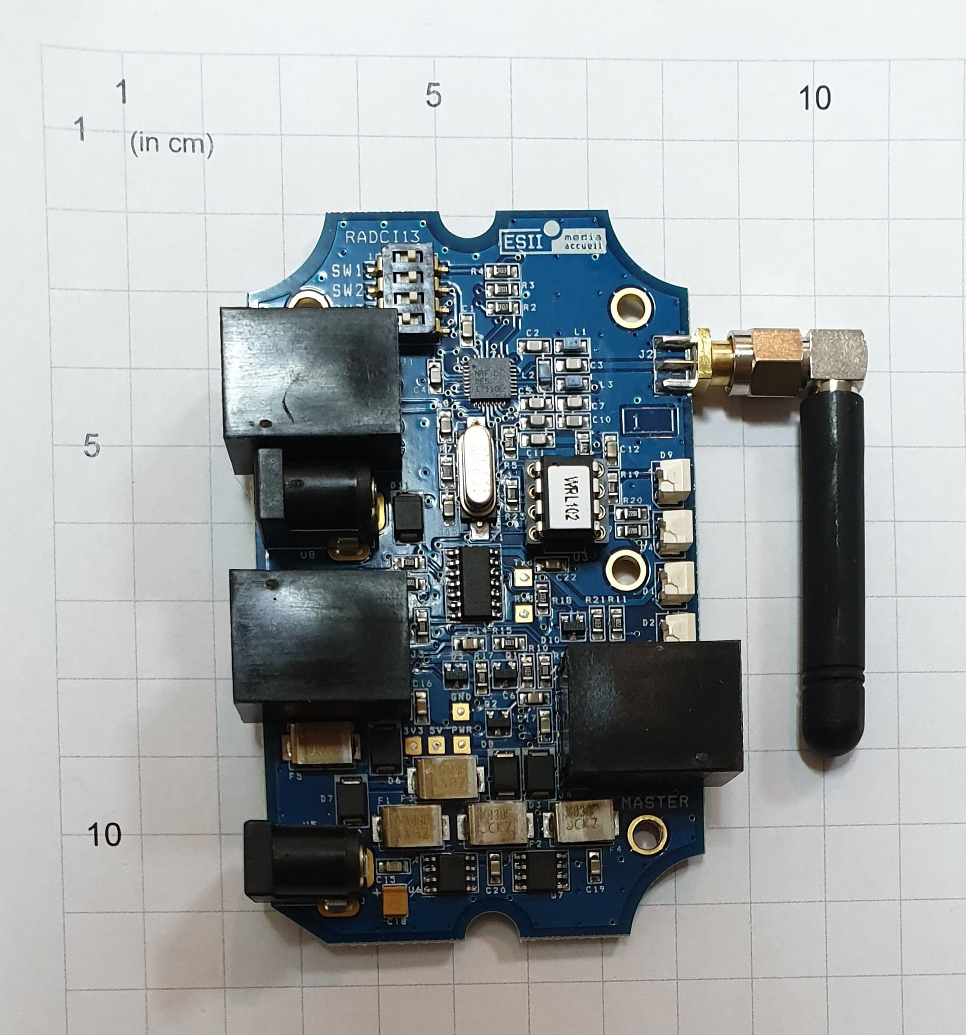
Click to zoom
Application Details
- Equipment Class
- DXX - Part 15 Low Power Communication Device Transmitter
- Date of Grant
- Apr 15, 2020
- Application Purpose
- Original Equipment
- Date of Application
- Apr 15, 2020
- Equipment Note
- Radio communication bridge for ticketless reception solution
- Frequency Range
- 915.00000000 - 920.00000000
- Company
- ESII
- Country
- France
Documents & Files
Document Text
Text extracted from the exhibit documents filed with the FCC. Open a document above to read the original.
Users Manual
Issue ITXT90 Ind.I Tous droit s réservé All rights reserved. © 2020 ESII CONDITIONS OF SITE’S LAY OUT Even if we use authorized radio channels, ESII certified equipments, we draw your attention on internal or external causes in your premises that can induce a lessening of the functional behavior of our systems of reception supervising, and in which ESII shall not be held responsible of, especially on the following points: • Interferences due to external causes, sporadically or permanently. • Topography and structure of your premises (contact us). • Non respect of ESII’s instructions. RESTRICTIONS OF USE RECEPTION SUPERVISOR SYSTEM (eGestat, Pilote, etc.) HUB RADIO MASTER SLAVE HUB RADIO RJ45 "MASTER" RJ45 "MASTER" NOT USED RJ45 "SLAVE" 230VAC-15VDC 15W 230VAC-15VDC 15W HUB RADIO SLAVE RJ45 "SLAVE" CONSOLE AUTOMATIC TICKET DISPENSER RJ45 "SLAVE" SLAVE 230VAC-15VDC 15W RJ45 HUB RADIO DISPLAYS VIDEO RJ45 "MASTER" NOT USED RJ45 "MASTER" NOT USED LIGHT PROCESSING EQUIPMENT RJ45 "SLAVE" NOT USED 25M MAX. 25M MAX. 25M MAX. RJ45 "SLAVE" RJ45 "SLAVE" The radio reach depends essentially on Master/Slave distance and depends on the environment. Generally, a limitation of 25m in direct vision of the Master/Slave distance allows to be protected against the major part of radio reach problems. And a minimum of 5m between 2 devices set on a different frequency. It is very important to be sure that radio waves are going through the minimum quantity of elements (partition, furniture, etc.) which reduce considerably the communication reach. Also check the nature of the walls (avoid concrete, metal parts, etc.) The positioning of the modules is decisive. It is important to free the radio modules from all interference sources (central processing unit, display, metal parts, etc.). For optimum communication, the environment of the radio modules must be free from all objects around 30cm at least. The modules must not be installed inside consoles or metal housings, etc. COMMUNICATION RECOVERY In case of fault communication, check the following points: - Check that all equipments are correctly supplied and wired. - After having checked the correct starting of the system, check that all status visual indicators of the radio link indicate a perfect communication (the red visual indicator, beside the antenna, must be lit without blinking and permanently). If one of the status visual indicators is off or blinks: - First, check detailed points described in the previous chapters: distances, heights, clearing of modules, etc. - Test the radio module showing communication failures by positioning it close to the “Master” to check its correct behavior. - Change the radio module showing communication failures by a new one. In case of serious radio reach, a good solution is to place the “Master” module at the center of the room or site to reduce distances at their lowest value. Issue ITXT90 Ind.I Tous droit s réservé All rights reserved. © 2020 ESII RADIO RELAY MODULE RADMO10(WRL102) ESII reports the RADMO10 complies with guidelines 2014/30/EU (CEM), 2014/35/EU (low voltage), 2014/53/UE (RED), EN 301-489-3 (CEM), EN 301-489-1 (CEM), EN 300 220-2 (RADIO), CEI 62311 (EMF), CEI 62368-1 (Electrical Safety), 2011/65/UE (ROHS) and 2012/19/UE (DEEE) This equipment has been tested and found to comply with the limits for a Class A digital device, pursuant to part 15 of the FCC Rules. These limits are designed to provide reasonable protection against harmful interference when the equipment is operated in a commercial environment. This equipment generates, uses, and can radiate radio frequency energy and, if not installed and used in accordance with the instruction manual, may cause harmful interference to radio communications. Operation of this equipment in a residential area is likely to cause harmful interference in which case the user will be required to correct the interference at his own expense. This device complies with part 15 of the FCC Rules and with Industry Canada licence- exempt RSS standard(s). Operation is subject to the following two conditions: (1) This device may not cause interference, and (2) This device must accept any interference, including interference that may cause undesired operation of the device. NOTE: The grantee is not responsible for any changes or modifications not expressly approved by the party responsible for compliance. Such modifications could void the user’s authority to operate the equipment ELEMENTARY CARES WARNINGS ▪ No part can be repaired by the user. In case of failure, please contact the maintenance service of the company ESII. ▪ Do not put the apparatus on an unstable or hot element. ▪ Do not open the housing for another reason than setting (only a qualified individual can perform this operation). ANTENNA ORIENTATION A B CRACK ! To orientate the antenna : 1. Loosen the connector’s nut (A). 2. Orientate the antenna (B). 3. Tighten the connector’s nut. CONNECTORS AND VISUAL INDICATORS 123 4 9 5 6 7 8 CONNECTORS 1. Supply connector 2. Peripheral #1 connector (“Slave”) 3. Peripheral #2 connector (“Slave”) 4. Reception supervising connector (“Master”) VISUAL INDICATORS 5. Green visual indicator: Tx Transmission of information to the ESII network. 6. Green visual indicator: Rx Reception of information from the ESII network. 7. Yellow visual indicator: Settings indicator At the starting of the module, it indicates during few seconds that the module is supplied. Then, this indicator gives the settings: • Lit: channel #1. • Blinking: channel #2. 8. Red visual indicator: Processing indicator A the starting of the module, it indicates during few seconds the protocol status: • Lit: EBUS protocol. • Off: reception protocol. Then, this indicator gives the communication quality status: • Lit: =100% (normal use). • Blinking: <100% (use limit reached). • Off: <75% (no or bad radio link). OTHER 9. Adjustable antenna FIXING Fixing the HUB RADIO must be done with the 2 adhesives supplied with the product. 1. …
Text truncated - open the document above for the full version.
Cover Letter(s)
Adresse du siège : ESII – ZI Sud – 2 rue de la Prade – 34880 LAVÉRUNE Adresse postale : ESII – ZI Sud Lavérune – 34433 St Jean de Vedas Cedex France Tél. : +33 (0)4 67 07 04 70 Fax : +33 (0)4 67 07 04 77 Internet : www.esii.com Email : [email protected] S.A.S. au capital de 527 448,60€ - SIRET 343 616 751 000 32 N° Identification FR 31 343 616 751 – RC Montpellier B 343 616 751 – NAF 3320C Federal Communications Commission Authorization and Evaluation Division Laverune, Thursday 17 January 2020 Subject: Confidentiality Request regarding application for certification of FCC ID: 2ATRJRAD Applicant: ESII Product: RADMO10 To Whom It May Concern: Pursuant to Sections 0.457 and 0.459 of the Commission’s Rules, we hereby request confidential treatment of information accompanying this application as outlined below: Exhibit Type File Name Block Diagram Schematics Operational Description Parts List RADMO10 BlkDia.pdf” RADMO10 Schem.pdf” RADMO10 Opdes.pdf” RADMO10 PartsLst.pdf The above materials contain trade secrets and proprietary information not customarily released to the public. The public disclosure of these materials may be harmful to the applicant and provide unjustified benefits to its competitors. The applicant understands that pursuant to Section 0.457 of the Rules, disclosure of this application and all accompanying documentation will not be made before the date of the Grant for this application. If you have any queries, please do not hesitate to contact us. Regards, David GELLY, 17 january 2020
Cover Letter(s)
Adresse du siège : ESII – ZI Sud – 2 rue de la Prade – 34880 LAVÉRUNE Adresse postale : ESII – ZI Sud Lavérune – 34433 St Jean de Vedas Cedex France Tél. : +33 (0)4 67 07 04 70 Fax : +33 (0)4 67 07 04 77 Internet : www.esii.com Email : [email protected] S.A.S. au capital de 527 448,60€ - SIRET 343 616 751 000 32 N° Identification FR 31 343 616 751 – RC Montpellier B 343 616 751 – NAF 3320C Laverune, 17 january 2020 Subject: RADIO Certification of RADMO10 Applicant: ESII Product: RADMO10 FCC ID: 2ATRJRAD IC ID: 25190-RAD To Whom It May Concern: We would like to submit the above product for Certification concerning FCC and Canadian rules. Please review all required documents enclosed. This is a ticketless reception solution. It displays dynamically the number of people waiting and when the counter calls, it starts vibrating, buzzing and displaying the point of service to go to. Compliance for RF exposure requirement was demonstrated in this test report. If you have any queries, please do not hesitate to contact us. Regards, David GELLY, 17 january 2020
External Photos
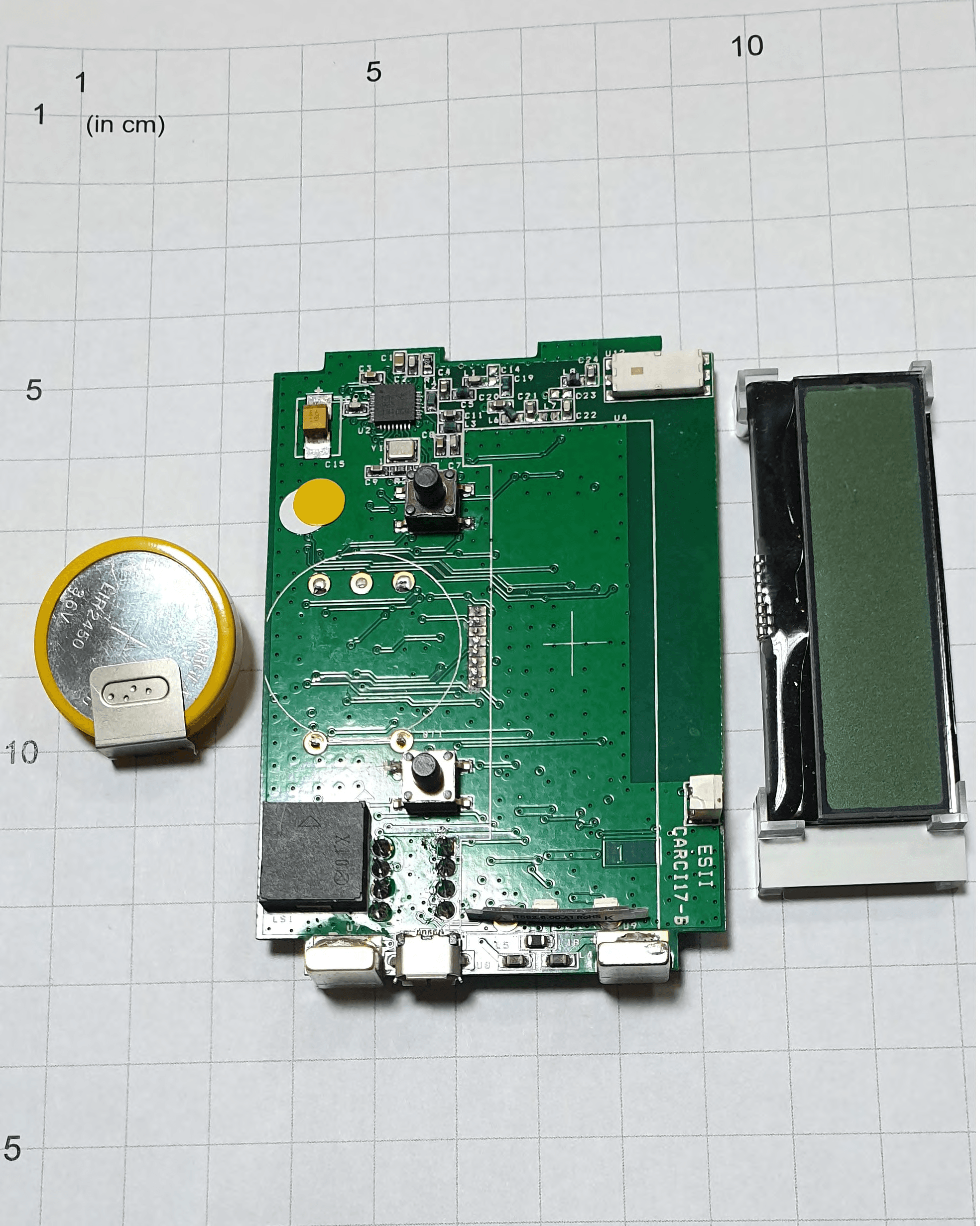
1 5 1 (in cm) 5 • •1 0 _ l 1 15 1 1 (in cm) • 10 \:lao 0· 1 :e~ mo ;an 1 15 5 ---=--;-------~-------------::----. • -.-. ......... .. ~ On Start e : EBUS 0: PACC Deviees Radio Quality ,. z ~ m z z )> e : 100°/o ' ~: < 100°/o '------.... 0 : < 75°/o On Start e: POWER ON 0: NO POWER Radio Configuration •: CHl 0: CH2 t;; r • HUB 1 Rx ... rx-. 0 (") x -t ..... 0 1 -J o. w 10 1 1 1 (in cm) 10 15 0 15 5 1 - l l 1 - 1 l 10 r 15 1 1 RADM010 48 WMax ~~24V-- Fcc ID 2ATRJRAD /IC 25190-RAD www.esil.com E~ll, SN: 137894 Copyright© - 10 -
Test Report
R412-19-100847-5A Ed.0 Duplication of this test report is only permitted for an integral photographic facsimile. It includes the number of pages referenced here above. This document is the result of testing a specimen or a sample of the product submitted. It does not imply an assessment of the conformity of the whole manufactured products of the tested sample. Siège Social : Emitech - 3, rue des Coudriers - CAP 78 - ZA de l’Observatoire - 78180 MONTIGNY LE BX - France Siret : 344 545 645 00022 - Tél. : 33 (0)1 30 57 55 55 - Fax : 33 (0)1 30 43 74 48 - E-mail : [email protected] - URL : www.emitech.fr S.A. au capital de 1 560 000 € - R.C.S. VERSAILLES 344 545 645 - APE 7112B LISTE DES SITES ACCREDITES ET PORTEES DISPONIBLES SUR WWW.COFRAC.FR ACCREDITATIONS N° 1-0107, 1-0826, 1-0827,1-1925, 1-2069,1-2070, 1-2376 & 1-6086 Test report issued under the responsibility of: EMITECH MONTPELLIER laboratory MRA US-EU Designation Number: FR0006 IC Assigned Code: FR0003 RADIO TEST REPORT FCC part 15.249 RSS-210 Issue 10 Company ......................................... : ESII Address............................................. : 2 RUE DE LA PRADE 34880 LAVERUNE FRANCE Test item description. .................... : GATEWAY Trade Mark. ...................................... : ESII Manufacturer. ................................... : ESII Model/Type reference. ...................... : V3/RADMO10 FCC ID. ............................................. : 2ATRJRAD IC. ..................................................... : 25190-RAD Ratings.............................................. : 100-240Vac/50-60Hz Testing Laboratory ......................... : EMITECH MONTPELLIER laboratory Address............................................. : 145 rue de Massacan 34740 VENDARGUES FRANCE Report Reference No. ..................... : R412-19-100847-5A Test procedure. ................................ : FCC IC Certification Diffusion. ........................................... : M. GELLY Applicant’s name. ............................. : ESII Date of issue. .................................... : 14/04/2020 Total number of pages. ..................... : 41 Revision. ........................................... : 0 Modified page(s). .............................. : Creation Compiled by. ..................................... : Morgan PATEY Approved by (+ signature). ............... : David MONTAULON (Technical Manager) R412-19-100847-5A Ed.0 Page 2 on 41 REPORT INDEX: 1. GENERAL INFORMATIONS .......................................................................................................................... 3 2. REFERENCE DOCUMENT(S) ........................................................................................................................ 4 3. EQUIPMENT TECHNICAL DESCRIPTION .................................................................................................... 5 3.1. TEST CONDITIONS ................................................................................................................................... 5 3.2. EUT GENERAL VIEW ............................................................................................................................... 5 3.3. EUT MARKING PLATE .............................................................................................................................. 6 3.4. EUT ELECTRONIC BOARD ........................................................................................................................ 7 3.5. EUT MECHANICAL AND ELECTRICAL DESIGN ............................................................................................. 8 3.6. EUT INPUT/OUTPUT PORTS ...................................................................................................................... 8 3.7. EUT RADIO SPECIFICATIONS .................................................................................................................... 9 4. RESULT SUMMARY ..................................................................................................................................... 10 5. RF EXPOSURE ............................................................................................................................................. 11 6. MEASUREMENT UNCERTAINTY ................................................................................................................ 12 7. TEST CONDITIONS AND RESULTS ........................................................................................................... 13 7.1. CONDUCTED EMISSION (MEASUREMENT) ................................................................................................. 13 7.2. OCCUPIED BANDWIDTH .......................................................................................................................... 17 7.3. 20DB BANDWIDTH .................................................................................................................................. 21 7.4. FIELD STRENGTH OF FUNDAMENTAL ........................................................................................................ 25 7.5. BAND EDGE ........................................................................................................................................... 26 7.6. RADIATED SPURIOUS EMISSIONS ............................................................................................................. 29 R412-19-100847-5A Ed.0 Page 3 on 41 1. GENERAL INFORMATIONS This document submits the results of Radio tests performed on the equipment GATEWAY (denominated hereafter E.U.T.: equipment under test) according to document(s) listed in §2 of this test report. TESTING PROCEDURE AND TESTING LOCATION: Testing Laboratory ..................................... : EMITECH MONTPELLIER laboratory & Open Area Test Site in SALINELLES (30) Address......................................................... : 145 rue de Massacan 34740 VENDARGUES FRANCE Test proced…
Text truncated - open the document above for the full version.
Test Setup Photos
R412-19-100847-5A Ed.0 Page 30 on 41 CATEGORY BRAND TYPE IDENTIFIER CAL. DATE CAL. DUE Cable MegaPhase N-8m 15813 12/11/2018 12/01/2021 Cable Huber + Suhner SF102K 16041 28/02/2019 28/04/2021 Cable MegaPhase TM18-N1N1-118 12841 09/05/2018 09/07/2020 Cable MegaPhase TM18-N1N1-118 12842 09/05/2018 09/07/2020 Filter Micro-Tronics HPM18865 12843 08/06/2018 08/08/2020 Preamplifier IMPULSE CA118-546ACN 9169 29/10/2018 29/12/2019 Receiver Agilent Technologies E4440A 5824 18/04/2018 18/06/2020 Receiver Rohde & Schwarz FSW43 14830 28/12/2018 28/02/2020 Shielded enclosure RAY PROOF C.V1 1123 Shielded enclosure COMTEST SAC 3m 14494 14/02/2017 14/04/2020 Software Nexio 0000 Thermohygrometer Testo 608-H1 7561 25/01/2019 25/03/2021 Thermohygrometer Testo 608-H2 12269 27/11/2017 27/01/2020 Thermohygrometer Bioblock Scientific Météostar 0963 25/01/2019 25/03/2021 Turntable INN-CO CO3000 & DS1200S 11571 BAT-EMC software version: V3.18.0.26 Blank cells = Permanent validity TEST SETUP PHOTO(S) – SPURIOUS – EUT R412-19-100847-5A Ed.0 Page 31 on 41 TEST SETUP PHOTO(S) – SPURIOUS – 9KHZ TO 30 MHZ TEST SETUP PHOTO(S) - SPURIOUS – 30MHZ TO 200 MHZ R412-19-100847-5A Ed.0 Page 32 on 41 TEST SETUP PHOTO(S) - SPURIOUS – 200MHZ TO 1GHZ TEST SETUP PHOTO(S) - SPURIOUS – > 1GHZ R412-19-100847-5A Ed.0 Page 14 on 41 TEST SETUP PHOTO(S) - 110VAC/60HZ POWER SUPPLY EC-test.JP G TEST SETUP PHOTO(S) - 110VAC/60HZ POWER SUPPLY - HUB EC-test2.JP G
Contact Information
Applicant
david gelly
Test Firm
EMITECH MontpellierOlivier HEYER
Technical Specifications
| # | Rule Parts | Frequency Range | Power Output |
|---|---|---|---|
| 1 | 15C | 915 MHz - 920 MHz | - |
Other Applications from ESII
2ATRJWS
Apr 07, 2020Ticketless Reception Solution
Equipment Class
DXX - Part 15 Low Power Communication Device Transmitter