2ATRP-SWITCHSWITCH
Kangaroo Media Inc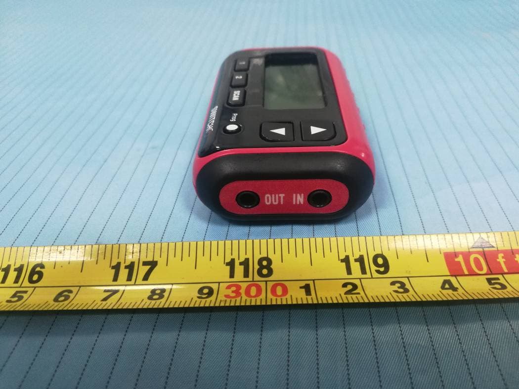
Click to zoom
Application Details
- Equipment Class
- CSR - Scanning Receiver
- Date of Grant
- Jan 20, 2020
- Application Purpose
- Original Equipment
- Date of Application
- Jan 18, 2020
- Equipment Note
- SWITCH
- Frequency Range
- 450.00000000 - 470.00000000
- Company
- Kangaroo Media Inc
- Country
- Canada
Documents & Files
Document Text
Text extracted from the exhibit documents filed with the FCC. Open a document above to read the original.
Users Manual
Racing Electronics SWITCH Manual Version 2.0 11/05/2017 Racing Electronics SWITCH DESCRIPTION Always hear the Race Officials over your Team Radio conversations. This is what the SWITCH does. The Racing Electronics SWITCH And SWITCH RACER combine a 2 Channels Radio Receiver with an Audio Input Port and an Audio Output Port. The Audio Input Port is connected to the output of your 2 way radio. It is internally looped to the Output Port where your headsets are connected so that you normally hear the conversation with your Team. Messages from Officials are detected by the built in Receiver and immediately routed to your headsets. When this happens, your 2 way Radio Audio is attenuated. The frequencies of the 2 channels are Preset but programmable. The Switch is however fully versatile to be used different ways as follow: 1. The Audio from the Audio Input Port is not mandatory. If used, it will always be attenuated when activity is detected on a Preset Channel. You can connect any audio source to that port. 2. The Preset Channels can be used as follow: a. Hold on Preset Channel 1 (Always the default at power ON. Fully programmable) b. Hold on Preset Channel 2 (Fully programmable) c. SCAN Preset Channel 1 or 2. (activity must finish on an active channel before switching to other channel. Not available in SWITCH RACER) d. SCAN with Priority on Preset Channel 1. (Channel 1 interrupts channel 2. Not available on SWITCH RACER) e. SCAN with Priority on Preset Channel 2. (Channel 2 interrupts channel 1. Not Available on SWITCH RACER) The SWITCH is shipped with Preset Channel 1 programmed at 454.0000 MHz, the frequency for the NASCAR Officials. You can however reprogram the frequency to any of the available 12.5 Khz bandwidth channels in the 450-470 MHz range. It is fully compliant with today’s Motor Racing sanctioning body. The SWITCH takes advantage of the Analog and Digital Squelch technology (DTCSS/CDCSS, PL/DPL from Motorola TM ). Using that sub Channel technology insures that if a frequency is used by more than one team, you can select to listen only to the one you want from its sub Channel number. The SWITCH generates distortion free audio, loud enough for the race environment. The Audio Input Port accepts 1/8 jack, mono or stereo. Headsets with 1/8’’ mono or stereo jack can be connected to the Audio Output Port. The Switch Operates from 2 AAA batteries. Normal Alcaline batteries provide 7 hours of continuous operation. A Battery Low indicator turns ON when you still have only 30 minutes of full Racing Electronics SWITCH Manual Version 2.0 11/05/2017 operation. After that, the Radio receiver is turned OFF. In that mode, you still have 5 hours of operation but from the Audio Input Port only. The SWITCH comes with 2x AAA batteries, a lanyard & instruction manual. SPECIFICATIONS Features Audio In: Yes, cabled Always muted when one RF Channel is active. RF Channels: 2, from built in Radio receiver Preset but programmable by user Automatic scan: Between preset channels 1 and 2 only. (Not available on SWITCH RACER) Functionality: Hold on Channel Ch1 or Ch2, Scan, Scan Priority Ch1, SCAN Priority Ch2 (Not available on SWITCH RACER) Operation: Normal (Audio In, Ch1 or Ch2) Battery Low (Audio In, CH1 or Ch2) Bypass mode (Audio In only, RF receiver is OFF when battery too low) Battery Low Indicator: Yes Built In memory: Yes, (last preset saved, even when changing batteries) Compliance: Compliant with official Motor Racing sanctioning body. RF Radio Receiver Frequency Range: 450 MHz to 470 MHz Channels Bandwidth: 12.5 KHz, for a total of 1600 channels Sub Channel Technology: Analog CTCSS or PL (Motorola TM ) Digital CDCSS or DPL (Motorola TM ) Mechanical: Dimensions: 3.00"W x 1.75"H x .80"D Weight: 0,2 g (without batteries) Electrical: Audio Input: 1/8” (3.5mm) Stereo socket, accepts mono and Stereo jack Audio Output: 1/8” (3.5mm) for Stereo earbuds/Headsets, 8 to 32 Ohms Audio Output Level: User adjustable for internal RF receiver. Audio from Audio In adjusted from connected device only. Power: Batteries: 2x AAA (included) Battery life: 7 Hours (continuous) + 5 Hours in bypass mode Accessories: Included: Lanyard with safety clip and quick detach User manual Optionnal accessories: Belt-clip Earbuds Racing Electronics SWITCH Manual Version 2.0 11/05/2017 Racing Electronics ‘’Switch’’ Operation OPERATION MODE (Default mode when you power ON) Audio In Audio In. Used to connect a Radio device, Cell phone or Music player. The volume level for that input is controlled by the connected device only. This audio input is always attenuated whenever a signal is present on Preset Channel 1 or 2. Accepts mono or stereo 1/8’’ jack. Audio Out Audio Out. Used to connect headphones or earbuds. Accepts 1/8’’ mono or stereo jack. Power ON-OFF. Hold for 2 Seconds to power ON-OFF. Preset Channel 1. Press to select Preset Channel 1. This Channel is always the default at power ON. Its as shipped value is NASCAR Officials frequency of 454.0000 Mhz. Preset Channel 2. Press to select Preset 2. SCAN, Press to SCAN between Preset 1 and 2. Once a conversation on one of the Preset is active, it must terminate before the scanning process resumes. (Not Available on SWITCH RACER) SCAN Priority 1, Hold and press to start SCAN with Priority on Preset 1. If Preset 1 becomes active, it will interrupt Preset 2. (Not Available on SWITCH RACER) SCAN Priority 2, Hold and press to start SCAN with Priority on Preset 2. If Preset 2 becomes active, it will interrupt Preset 1. (Not Available on SWITCH RACER) Volume UP. Press to increase volume of Preset 1 or 2. Volume Down. Press to decrease volume of Preset 1 or 2. Long Press PROGRAMMING. Hold for 2 seconds to enter programming mode. Details are provided below, in the Programming Sections. Long Press Hold for 2 seconds to display Preset 1 sub channel information. Long Press Hold for 2 seconds to display Preset 2 sub channel information. PROGRAMMING (Basic) Long Press PROGRAMMING Mode access. Hold for…
Text truncated - open the document above for the full version.
Attestation Statements
Kangaroo Media Inc Address: 20865 Ch de la Cote nord, suite 101 Boisbriand, Quebec, J7E 4H5 Canada Tel.: 450-595-2023 Fax: 450-595-2023 E-mail: [email protected] 2020-01-21 Federal Communications Commission Authorization and Evaluation Division, 7435 Oakland Mills Road Columbia, MD 21046 USA Re: SWITCH (FCC ID: 2ATRP-SWITCH) Gentlemen: The scanner receiver equipment meets the requirements of the FCC Rules, 15.121 (a). Compliance is achieved through the following methods: The scanner receiver in this equipment is incapable of tuning, or readily being altered, by the User to operate within the frequency bands allocated to the Domestic Public Cellular Telecommunications Service in Part 22. Blocking of the cellular frequencies is implemented in the firmware of the unit’s main control central processing unit (CPU). Coverage of 824 -849 MHz and 869 - 894 MHz is completely blocked, since it is done in the microprocessor,and cannot be re-enabled by any user-accessible procedure, including diode, resistor, or jumper changes, nor by connection of any external device such as a personal computer, nor by installation of any “special” enabling semiconductor device. The scanning receiver is designed so that the tuning, control and filtering circuitry is inaccessible. Sincerely, Kangaroo Media Inc Pascal M. Tremblay Project Manager
Cover Letter(s)
Kangaroo Media Inc Address: 20865 Ch de la Cote nord, suite 101 Boisbriand, Quebec, J7E 4H5 Canada Tel.: 450-595-2023 Fax: 450-595-2023 E-mail: [email protected] FCC Confidential Authorization Date: 2019-12-02 FEDERAL COMMUNICATIONS COMMISSIONS Authorization and Evaluation Division 7435 Oakland Mills Road Columbia, MD 21046 Subject: Confidentiality Request regarding application for certification of FCC ID: 2ATRP-SWITCH In accordance with Sections 0.457 and 0.459 of the Commission’s Rules, Kangaroo Media Inc hereby requests long-term confidential treatment of information accompanying this application as outlined below: Block Diagram Schematics Operation Description The above materials contain proprietary and confidential information not customarily released to the public. The public disclosure of these materials provides unjustified benefits to its competitors in the market. Sincerely Yours, Pascal M. Tremblay Project Manager Internal photos
Cover Letter(s)
Kangaroo Media Inc Address: 20865 Ch de la Cote nord, suite 101 Boisbriand, Quebec, J7E 4H5 Canada Tel.: 450‐595‐2023 Fax: 450‐595‐2023 E‐mail: [email protected] Product Similarity Declaration 2019-12-02 To: FEDERAL COMMUNICATIONS COMMISSIONS Authorization and Evaluation Division 7435 Oakland Mills Road Columbia, MD 21046 Dear Sir/Madam, We, Kangaroo Media Inc hereby declare that we have a product named as SWITCH (Model: SWITCH, FCC ID: 2ATRP-SWITCH) was tested by BACL, Meanwhile, for our marketing purpose, we would like to list a series model (SWITCH RACER) on reports and certificate. The two models have the same circuit. The differences are as follows: 1. The model name is different. 2. SWITCH RACER does not have the “SCAN” button. It has no SCAN function. We confirm that all information above is true, and we’ll be responsible for all the consequences. Please contact me if you have any question. Sincerely Yours, Pascal M. Tremblay Project Manager
External Photos
EXHIBIT B - EUT EXTERNAL PHOTOGRAPHS
ID Label/Location Info
EXHIBIT A - FCC ID LABEL AND LOCATION FCC ID Label FCC ID Label Location Information The label shown shall be permanently affixed at a conspicuous location on the device and be readily visible to the user at the time purchase (Labeling requirements per 2.925)
Test Report
Note: This report must not be used by the customer to claim product certification, approval, or endorsement by A2LA* or any agency of the Federal Government. This report may contain data that are not covered by the A2LA accreditation and are marked with an asterisk “★”. BACL is not responsible for the authenticity of any test data provided by the applicant. Data included from the applicant that may affect test results are marked with an asterisk ’*’. Customer model name, addresses, names, trademarks etc. are not considered data. This report cannot be reproduced except in full, without prior written approval of the Company. Unless otherwise stated the results shown in this test report refer only to the sample(s) tested. This report is valid only with a valid digital signature. The digital signature may be available only under the Adobe software above version 7.0. FCC PART 15B, CLASS B TEST REPORT For Kangaroo Media Inc 20865 Ch de la Cote nord, suite 101, Boisbriand, Quebec, J7E 4H5, Canada FCC ID: 2ATRP-SWITCH Report Type: Original Report Product Type: SWITCH Re port Number: RSZ191202004-00 Re port Date: 2020-01-15 Reviewed B y: Joson Xiao EMC En gineer Prepared By: Bay Area Compliance Laboratories Corp. (Shenzhen) 6/F., West Wing, Third Phase of Wanli Industrial Building, Shihua Road, Futian Free Trade Zone, Shenzhen, Guangdong, China Tel: +86-755-33320018 Fax: +86-755-33320008 www.baclcorp.com.cn Bay Area Compliance Laboratories Corp. (Shenzhen) Report No.: RSZ191202004-00 FCC Part 15B, Class B Page 2 of 17 TABLE OF CONTENTS GENERAL INFORMATION ....................................................................................................................................... 3 PRODUCT DESCRIPTION FOR EQUIPMENT UNDER TEST (EUT) ..................................................................................... 3 OBJECTIVE ................................................................................................................................................................... 3 RELATED SUBMITTAL(S)/GRANT(S) ............................................................................................................................. 3 TEST METHODOLOGY .................................................................................................................................................. 3 MEASUREMENT UNCERTAINTY .................................................................................................................................... 4 TEST FACILITY ............................................................................................................................................................. 4 SYSTEM TEST CONFIGURATION .......................................................................................................................... 5 DESCRIPTION OF TEST CONFIGURATION ...................................................................................................................... 5 EUT EXERCISE SOFTWARE .......................................................................................................................................... 5 SPECIAL ACCESSORIES ................................................................................................................................................. 5 EQUIPMENT MODIFICATIONS ....................................................................................................................................... 5 SUPPORT EQUIPMENT LIST AND DETAILS .................................................................................................................... 5 EXTERNAL I/O CABLE .................................................................................................................................................. 5 BLOCK DIAGRAM OF TEST SETUP ................................................................................................................................ 6 SUMMARY OF TEST RESULTS ............................................................................................................................... 7 TEST EQUIPMENT LIST ........................................................................................................................................... 8 FCC §15.109 - RADIATED SPURIOUS EMISSIONS .............................................................................................. 9 APPLICABLE STANDARD .............................................................................................................................................. 9 EUT SETUP .................................................................................................................................................................. 9 EMI TEST RECEIVER SETUP ....................................................................................................................................... 10 TEST PROCEDURE ...................................................................................................................................................... 10 CORRECTED AMPLITUDE & MARGIN CALCULATION ................................................................................................. 10 TEST RESULTS SUMMARY .......................................................................................................................................... 10 TEST DATA ................................................................................................................................................................ 11 FCC §15.121 - COMPLIANCE FOR SCANNING RECEIVER ............................................................................. 16 APPLICABLE STANDARD ............................................................................................................................................ 16 EUT SETUP .................................................................................................................................…
Text truncated - open the document above for the full version.
Test Setup Photos
EXHIBIT D - TEST SETUP PHOTOGRAPHS Radiated Emissions (Below 1 GHz) Radiated Emissions (Above 1 GHz)
Contact Information
Applicant
Pascal M. Tremblay(Project Manager)
Test Firm
Bay Area Compliance Laboratories Corp. (Shenzhen)Well Wang
[email protected]+86 (0) 755 33320018
Technical Specifications
| # | Rule Parts | Frequency Range | Power Output |
|---|---|---|---|
| 1 | 15B | 450 MHz - 470 MHz | - |