2ATURPW2DPleco Display
Nudge Systems LLC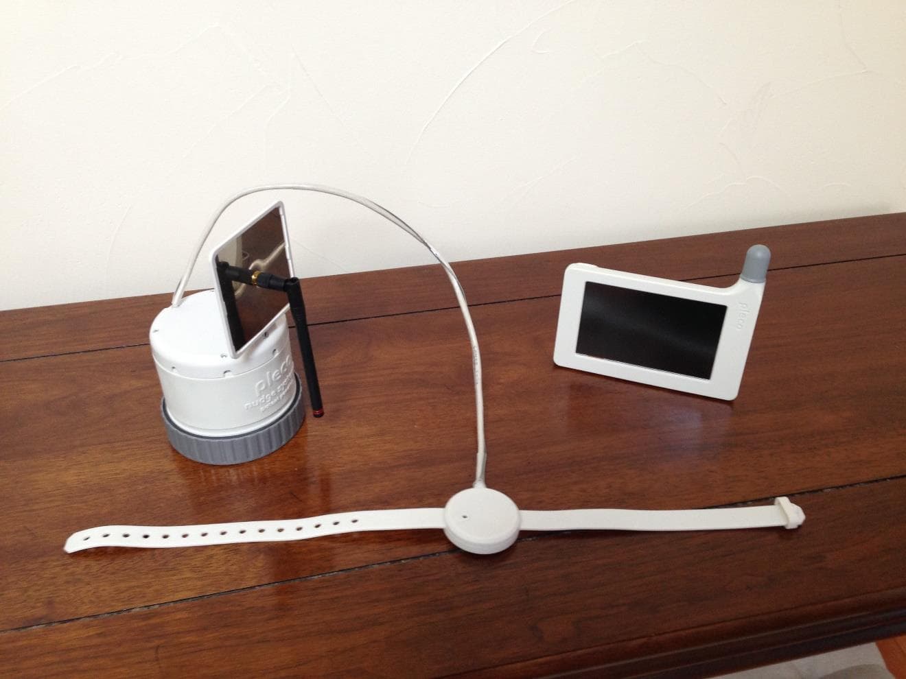
Click to zoom
Application Details
- Equipment Class
- DSC - Part 15 Security/Remote Control Transmitter
- Date of Grant
- Mar 24, 2020
- Application Purpose
- Original Equipment
- Date of Application
- Mar 24, 2020
- Equipment Note
- Pleco Display
- Frequency Range
- 433.92000000 - 433.92000000
- Company
- Nudge Systems LLC
- Country
- United States
Documents & Files
Document Text
Text extracted from the exhibit documents filed with the FCC. Open a document above to read the original.
Users Manual
nudge systems pleco TM Water Watch INSTRUCTION MANUAL Please read this manual before installation PACKAGE CONTAINS: Sensor Display Container USB charger USB cable Manual 1 TABLE OF CONTENTS Product Features .............................................................................. 2 Product Description ........................................................................... 2 Setup Instructions .............................................................................. 3 Display Screens ................................................................................ 4 Battery Replacement & Warnings ......................................................... 6 Care and Maintenance ....................................................................... 7 Warnings ......................................................................................... 7 Trouble Shooting .............................................................................. 8 FCC & ISED Information ..................................................................... 9 Contact Information ............................................................................ 9 2 FEATURES - The Pleco Sensor mounts to an existing water meter and provides water consumption information to the user through the Pleco Display and the Pleco smartphone app. - Water consumption information is provided in near real-time. - Detects different types of water usage: Faucet, flush, shower, irrigation, and other. Usage identification is not 100% accurate due to variability in water supply installations. - Easy setup, no tools required to install. DESCRIPTION SENSOR: The Pleco sensor attaches to a functioning water meter and sends water usage information in near real time to the Pleco display. No tools are required to attach the sensor to the water meter. The sensor uses four (4) standard D-cell batteries that on average are expected to last over four months before being replaced. DISPLAY: The Pleco 5-inch touch-screen display receives sensor data and shows water usage in near real time. It works as a hub connecting to the Internet and the smartphone app. It can be wall mounted or placed on a counter or desk. The display should be within 50 ft. distance from the sensor for effective communication. It comes with a rechargeable battery that lasts over 1-hour. It is recommend to keep the display connected to the external power supply for continuous use. CONTAINER: The container used to ship Pleco is also used to calibrate the system. During calibration you will fill the container to the 1-Gallon water mark in order to start the system. All foam packaging materials should be removed from the container prior to calibration. APP: The Pleco app will show water usage in near real-time in your smartphone. It displays information similar to that on the Pleco display and provides a convenient way to monitor your water usage when you are away. 3 SETUP INSTRUCTIONS 1. Unpack and Power Up - Package contains: Sensor, Display, Container, USB charger, and USB cable. - Connect the power supply to an outlet and to the display and turn on the display. - Follow setup instructions on the display. 2. Attach sensor to water meter - Locate your water meter and make sure it’s sides are accessible. - Attach the sensor around the water meter (as a belt). Do NOT block the water meter reading dial. - Rest the battery enclosure on the ground. 3. Deploy sensor antenna - Unfold sensor antenna. - Use the telescoping mast to move the antenna up as close as possible to ground level. - Rotate antenna so that it is oriented parallel to the front of the house. 4. Setup and calibration - Use the display to setup the system, adjust date/time, connect to Wi-Fi, and to register. - Follow instructions on the display to initialize and calibrate the sensor. Remove all foam from container prior to calibration. - To power up the sensor tighten the battery enclosure lid. LED will light up. After initialization LED stays off. - Pleco is ready to use. 5. Install the smartphone app - The Pleco app is available at no extra cost at the Apple Store and Google Play. 4 DISPLAY SCREENS The Pleco display and smartphone app user interface consists of several screens used to provide water usage information and change system settings. The user navigates through the various screens by selecting the icons and menus on the touch-screen display and smartphone app. Home Screen The Home screen shows the total water usage in the current day and time. It also displays a daily water usage limit that is set to a default value and can be changed by the user through the settings screen. Information on sensor signal strength, time, wi-fi connection, and battery charge are shown on the top of the screen. Icons on the right of the screen are used to navigate to other screens as indicated in the figure below. What Screen The What screen shows what the water was used for. The system identifies 5 different types of water usage: Faucet, flush, shower, irrigation, and other. Due to variations in the water supply systems, the identification is not perfect and some water usage may be misidentified. Icons on the right of the screen are used to select usage for the current day, week, or month as shown in the figure below. Touching the pie chart will show the water used for the type selected. Sensor signal strength wi-fi connection Display battery charge Sensor low-battery warning What screen When screen Settings screen Daily water usage and Time history screen Daily water usage limit Time Water usage left to reach daily limit Current day Current week Current month Time history screen Home screen 5 When Screen The When screen shows when the water was used. Icons on the right of the screen are used to select usage within the current day, week, or year as shown in the figure below. The scale icon on the top-right of the screen toggles between showing and hiding the usage for the previous time period for comparison. Time His…
Text truncated - open the document above for the full version.
Cover Letter(s)
July 14, 2019 Federal Communications Commission Authorization & Evaluation Division 7345 Oakland Mills Road Columbia, Maryland 21046 nud g e systems RE: Short-Tenn Confidentiality Request for EUT MODEL PW2 and Grantee Code 2ATUR FCC ID: 2ATURPW2S and 2ATURPW2D To Whom It May Concern: In accordance with sections 0.457 and 0.459 of CFR 47, Nudge Systems requests Short-Term Confidentiality for the following exhibi1s of this application for a period of 180 days after grant is issued: 1. Test setup photos 4.User's manual 2. External photos3. Internal photos These documents contain detailed system and equipment descriptions and related information about the product, which manufacturer/applicant considers to be proprietary. confidential, and a custom design and otherwise, would not release to the general public. Since this design is a basis from which future technological products will evolve, manufacturer/applicant feels that this information would be of benefit to its competitors, and that the disclosure of the information in these documents would give our competitors an unfair advantage in the market. Grantee will not market or distribute product during the Short-Term Confidentiality period requested. When the device is ready to be marketed the grantee will inform the TCB to release the Short-Term Confidentiality. Please contact me if there is any information you may need. Sincerely, Ana Pedreiro President Nudge Systems, LLC
External Photos
Nudge Systems Proprietary Information Nudge Systems Proprietary Information 1 PLECO DISPLAY UNIT (DU) EXTERNAL PHOTOS October 20, 2019 Subject: Nudge Systems - FCC ID: 2ATURPW2D FRN: 0028614873 - EIN: 475343663 – ISED: 25251-PW2 FCC Grantee Code: 2ATUR FCC Grantee Code Registration Number: GC741333 To: Compliance Testing John Reynolds, TCB Manager 1724 S. Nevada Way Mesa, AZ 85204 (P) 480.926.3100 / (F) 480.926.3598 [email protected] From: Nudge Systems Ana Pedreiro, President 230 Oak Ct. Menlo Park, CA 94025 phone. 650-799-6101 [email protected] Nudge Systems Proprietary Information Nudge Systems Proprietary Information 2 1. PLECO PRODUCT PICTURES FOR FCC CETIFICATION The Pleco product consists of a Display Unit (DU) and a Sensor Unit (SU) as shown in Figure 1. Both units are required for operation. Fig. 1: Pleco product: Display Unit (DU) and Sensor Unit (SU) Display Unit (DU) Sensor Unit (SU) Nudge Systems Proprietary Information Nudge Systems Proprietary Information 3 2. DISPLAY UNIT (DU) PHOTOS – EXTERNAL FCCID: 2ATURPW2D Figure 2 shows the various external views of the Display Unit (DU). The DU contains a built in 433 MHz helical antenna that can only be assessed through complete disassembly of the unit. Fig. 2a: DU Front view Fig. 2b: DU Back view Fig. 2c: DU Side view Fig. 2d: DU Side view Fig. 2e: DU Top view Fig. 2f: DU Bottom view Antenna 433 MHz Nudge Systems Proprietary Information Nudge Systems Proprietary Information 4 3. PLECO PRODUCT – MAIN DIMENSIONS The Pleco product consists of a Display Unit (DU) and a Sensor Unit (SU) as shown in Figure 3. Both units are required for operation. The main dimensions of the DU and SU are shown in the figure. Fig. 3: Pleco product main dimensions Display Unit (DU) Sensor Unit (SU) 3.6 in. 5.2 in. 6.0 in. 3.8 in. 7.0 in. 4.2 in. dia. 2.1 in. dia. 19.8 in.
ID Label/Location Info
Nudge Systems Proprietary Information Nudge Systems Proprietary Information 1 1. PLECO DISPLAY UNIT (DU) - LABEL The Display Unit (DU) will use e-label to display regulatory information. As shown in Figure 1, only two (2) steps are necessary for the user to access regulatory information: From the Home screen the user selects Settings and from the Settings screen the user selects “Regulatory”, which displays the e-label containing the FCC ID and other regulatory information. Fig. 1: User access to regulatory information Step 1: User selects Settings From the Home screen Step 2: User selects Regulatory From the Settings screen Limit Licenses/Notices Units About Wi-Fi Setup Firmware Update Calibration LCD Brightness Regulatory Time and Date Pairing Regulatory information including FCC ID is displayed Nudge Systems Proprietary Information Nudge Systems Proprietary Information 2 Figure 2 shows the Display Unit (DU) electronic label in the size as seen by the user in the screen. Fig. 2: DU screen showing regulatory information label in the size as seen by the user. 2. COMPLIANCE WITH KBD 784748 D02 Following are description of compliance to KDB 7847748 D02, sections 4.1 through 4.6: Section 4.1: User Steps to Access Information – As described in the previous paragraphs (Section 1) no access codes are required for the user to access regulatory information and only two (2) steps are required to access the information. Therefore, the Pleco Display Unit (DU) complies with Section 4.1 KDB 7847748 D02. Section 4.2: Products must not require special accessories or supplemental plug-ins to access the information – No special accessories or access code is required to access regulatory information (Section 1). Therefore, the Pleco Display Unit (DU) complies with Section 4.2 KDB 7847748 D02. Section 4.3: Readability of Regulatory Information – Figure 2 shows the regulatory label in the size as seen by the user in the LCD screen. The font size is 10 points and the information clearly legible without need for magnification. Therefore, the Pleco Display Unit (DU) complies with Section 4.3 KDB 7847748 D02. Section 4.4: Regulatory Information must be secure – The regulatory information is implemented at the factory and stored in non-volatile memory in the Display Unit (SU). It is stored locally in the device and easily accessible to the user. It is also secure and Nudge Systems Proprietary Information Nudge Systems Proprietary Information 3 cannot be changed by the user ensuring the correct information is displayed. Therefore, the Pleco Display Unit (DU) complies with Section 4.4 KDB 7847748 D02. Section 4.5: Physical and Temporary label for Purchasing and Importation – An adhesive label containing regulatory information including FCC ID (Fig. 3) is attached to the product packaging. Therefore, the Pleco product complies with Section 4.5 KDB 7847748 D02. Fig. 3: Adhesive label on the packaging Section 4.6: Additional Considerations – The Display Unit (DU) uses a modular Wi-Fi transmitter and the regulatory information is included in the electronic label screen as shown in Figure 2: “Contains FCC ID: 2ADHKATWINC1500”. Therefore, the Pleco Display Unit (DU) complies with Section 4.6 KDB 7847748 D02.
Internal Photos
Nudge Systems Proprietary Information Nudge Systems Proprietary Information 1 PLECO DISPLAY UNIT (DU) INTERNAL PHOTOS October 20, 2019 Subject: Nudge Systems - FCC ID: 2ATURPW2D FRN: 0028614873 - EIN: 475343663 – ISED: 25251-PW2D FCC Grantee Code: 2ATUR FCC Grantee Code Registration Number: GC741333 To: Compliance Testing John Reynolds, TCB Manager 1724 S. Nevada Way Mesa, AZ 85204 (P) 480.926.3100 / (F) 480.926.3598 [email protected] From: Nudge Systems Ana Pedreiro, President 230 Oak Ct. Menlo Park, CA 94025 phone. 650-799-6101 [email protected] Nudge Systems Proprietary Information Nudge Systems Proprietary Information 2 1. PLECO PRODUCT PICTURES FOR FCC CETIFICATION The Pleco product consists of a Display Unit (DU) and a Sensor Unit (SU) as shown in Figure 1. Both units are required for operation. Fig. 1: Pleco product: Display Unit (DU) and Sensor Unit (SU) Display Unit (DU) Sensor Unit (SU) Nudge Systems Proprietary Information Nudge Systems Proprietary Information 3 2. DISPLAY UNIT (DU) PHOTOS FCCID: 2ATURPW2D The Display Unit is built using a front and back shell that are connected using four fasteners and contain the internal components: Circuit Card Assembly, LCD touch screen, battery, and antenna (Figure 2). The DU contains a built in 433 MHz helical antenna that can only be assessed through complete disassembly of the unit. Fig. 2a: DU Front view Fig. 2b: DU Back view Antenna 433 MHz Nudge Systems Proprietary Information Nudge Systems Proprietary Information 4 3. DISPLAY UNIT PHOTOS – INTERNAL The Display Unit (DU) front and back shells are shown in Figures 3a and 3b. Fig 3a: DU front shell Fig 3b: DU back shell A 5-inch touch screen LCD is mounted to the front shell, followed by the DU antenna, circuit card assembly and battery as shown in Figure 3c. The back shell is then mounted to the front shell using 4 fasteners. Fig. 3c: DU internal assembly Circuit Card Assembly (CCA) Antenna 433 MHz Battery Touch screen LCD Nudge Systems Proprietary Information Nudge Systems Proprietary Information 5 Figures 3d and 3e show both sides of the DU circuit card assembly. Fig. 3d: DU circuit card assembly: Front side view. Fig. 3e: DU circuit card assembly: Back side view. Nudge Systems Proprietary Information Nudge Systems Proprietary Information 6 The DU contains a Wi-Fi module that is an Atmel device p/n ATWINC1500-MR210PB, which has been granted modular approval (FCC ID: 2ADHKATWINC1500). The module includes a 2.4 GHz antenna. Figure 3f shows a close up view of the Wi-Fi module, including a view of the integrated antenna. Fig 3f: Close-up view of Wi-Fi module (Atmel part number ATWINC1500-MR210PB) WiFi module with integrated 2.4GHz antenna (FCC ID: 2ADHKATWINC1500) (IC ID: 20266-ATWINC1510) Nudge Systems Proprietary Information Nudge Systems Proprietary Information 7 4. PLECO PRODUCT – MAIN DIMENSIONS The Pleco product consists of a Display Unit (DU) and a Sensor Unit (SU) as shown in Figure 4. Both units are required for operation. The main dimensions of the DU and SU are shown in the figure. Fig. 4: Pleco product main dimensions Display Unit (DU) Sensor Unit (SU) 3.6 in. 5.2 in. 6.0 in. 3.8 in. 7.0 in. 4.2 in. dia. 2.1 in. dia. 19.8 in.
Test Report
p1940005_FCC_Part 15.231_Rev 3.0 Page 1 of 14 Test Report Prepared for : Nudge system Model: Pleco Display, PW2D Description: Water Usage measurement Device Serial Number: NA FCC ID: 2ATURPW2D IC ID: 25251-PW2D To FCC Part 15.231 & RSS 210 Date of Issue: February 8 TH , 2020 On the behalf of the applicant: Nudge systems 230 Oak CT. Menlo Park, CA 94025 Attention of: Nelson Pedreiro Ph: (650)387-4760 E-mail: [email protected] Prepared by Compliance Testing, LLC 1724 S. Nevada Way Mesa, AZ 85204 (480) 926-3100 phone / (480) 926-3598 fax www.compliancetesting.com Project No: p1940005 Poona Saber Project Test Engineer This report may not be reproduced, except in full, without written permission from Compliance Testing. All results contained herein relate only to the sample tested. p1940005_FCC_Part 15.231_Rev 3.0 Page 2 of 14 Test Report Revision History Revision Date Revised By Reason for Revision 1.0 February 8 th , 2020 Poona Saber Original Document 2.0 March 12 th , 2020 Poona Saber Added model number PW2D Added average measurement methods on page 9 3.0 March 23,2020 Poona Saber Revised duty cycle factor, power level and average measurements of fundamental and spurious p1940005_FCC_Part 15.231_Rev 3.0 Page 3 of 14 Table of Contents Description Page STANDARD TEST CONDITIONS ENGINEERING PRACTICES .................................................................................................................. 6 TEST RESULTS SUMMARY .................................................................................................................................................................. 8 FIELD STRENGTH OF FUNDAMENTAL AND SPURIOUS EMISSIONS ..................................................................................................... 9 99% OCCUPIED BANDWIDTH ........................................................................................................................................................... 15 TEST EQUIPMENT UTILIZED ............................................................................................................................................................. 16 p1940005_FCC_Part 15.231_Rev 3.0 Page 4 of 14 ILAC / A2LA Compliance Testing, LLC, has been accredited in accordance with the recognized International Standard ISO/IEC 17025:2005. This accreditation demonstrates technical competence for a defined scope and the operation of a laboratory quality management system (refer to the joint ISO-ILAC-IAF Communiqué dated January 2009). The tests results contained within this test report all fall within our scope of accreditation, unless noted below. Please refer to http://www.compliancetesting.com/labscope.html for current scope of accreditation. Testing Certificate Number: 2152.01 FCC Site Reg. #349717 IC Site Reg. #2044A-2 Non-accredited tests contained in this report: N/A p1940005_FCC_Part 15.231_Rev 3.0 Page 5 of 14 The applicant has been cautioned as to the following 15.21: Information to User The user’s manual or instruction manual for an intentional radiator shall caution the user that changes or modifications not expressly approved by the party responsible for compliance could void the user’s authority to operate the equipment. 15.27(a): Special Accessories Equipment marketed to a consumer must be capable of complying with the necessary regulations in the configuration in which the equipment is marketed. Where special accessories, such as shielded cables and/or special connectors are required to enable an unintentional or intentional radiator to comply with the emission limits in this part, the equipment must be marketed with, i.e. shipped and sold with, those special accessories. However, in lieu of shipping or packaging the special accessories with the unintentional or intentional radiator the responsible part may employ other methods of ensuring that the special accessories are provided to the consumer, without an additional charge. Information detailing any alternative method used to supply the special accessories for a grant of equipment authorization or retained in the verification records, as appropriate. The party responsible for the equipment, as detailed in § 2.909 of this chapter, shall ensure that these special accessories are provided with the equipment. The instruction manual for such devices shall include appropriate instructions on the first page of text concerned with the installation of the device that these special accessories must be used with the device. It is the responsibility of the user to use the needed special accessories supplied with the equipment. p1940005_FCC_Part 15.231_Rev 3.0 Page 6 of 14 Standard Test Conditions Engineering Practices Except as noted herein, the following conditions and procedures were observed during the testing: In accordance with ANSI C63.10-2014 and unless otherwise indicated in the specific measurement results, the ambient temperature of the actual EUT was maintained within the range of 10° to 40°C (50° to 104°F) unless the particular equipment requirements specified testing over a different temperature range. Also, unless otherwise indicated, the humidity levels were in the range of 10% to 90% relative humidity. Measurement results, unless otherwise noted, are worst-case measurements. Environmental Conditions Temperature (°C) Humidity (%) Pressure (Mbar) 24-25.3 24.1-32.2 956-962 EUT Description Model: Pleco display, PW 2D Description: Water Usage measurement Device Serial Number: NA Highest Clock Frequency: Sensor -16 MHz Display- 336 MHz and 2.4 GHz WiFi module Additional Information: EUT consists of display unit (DU) and Sensor unit (SU) which will be paired together with a 433.92 MHz radio module and the operation and transmit power of the sensor unit is controlled by display unit which is served as the main user interface. Display unit has a rechargeable Li-Ion battery that is normally connected to AC/DC power adapter. It incorporated a pre- certified WiFi module which…
Text truncated - open the document above for the full version.
Test Setup Photos
Test Setup Photos FCC ID: 11223344 RF Radiated 30 MHz-1GHz RF Radiated 1-18 GHz
Contact Information
Applicant
Ana Pedreiro(President)
Test Firm
Compliance Testing, LLCMichael Schafer
Technical Specifications
| # | Rule Parts | Frequency Range | Power Output |
|---|---|---|---|
| 1 | 15.231(e) | 433.92 MHz - 433.92 MHz | - |
Other Applications from Nudge Systems LLC
2ATURPW2S
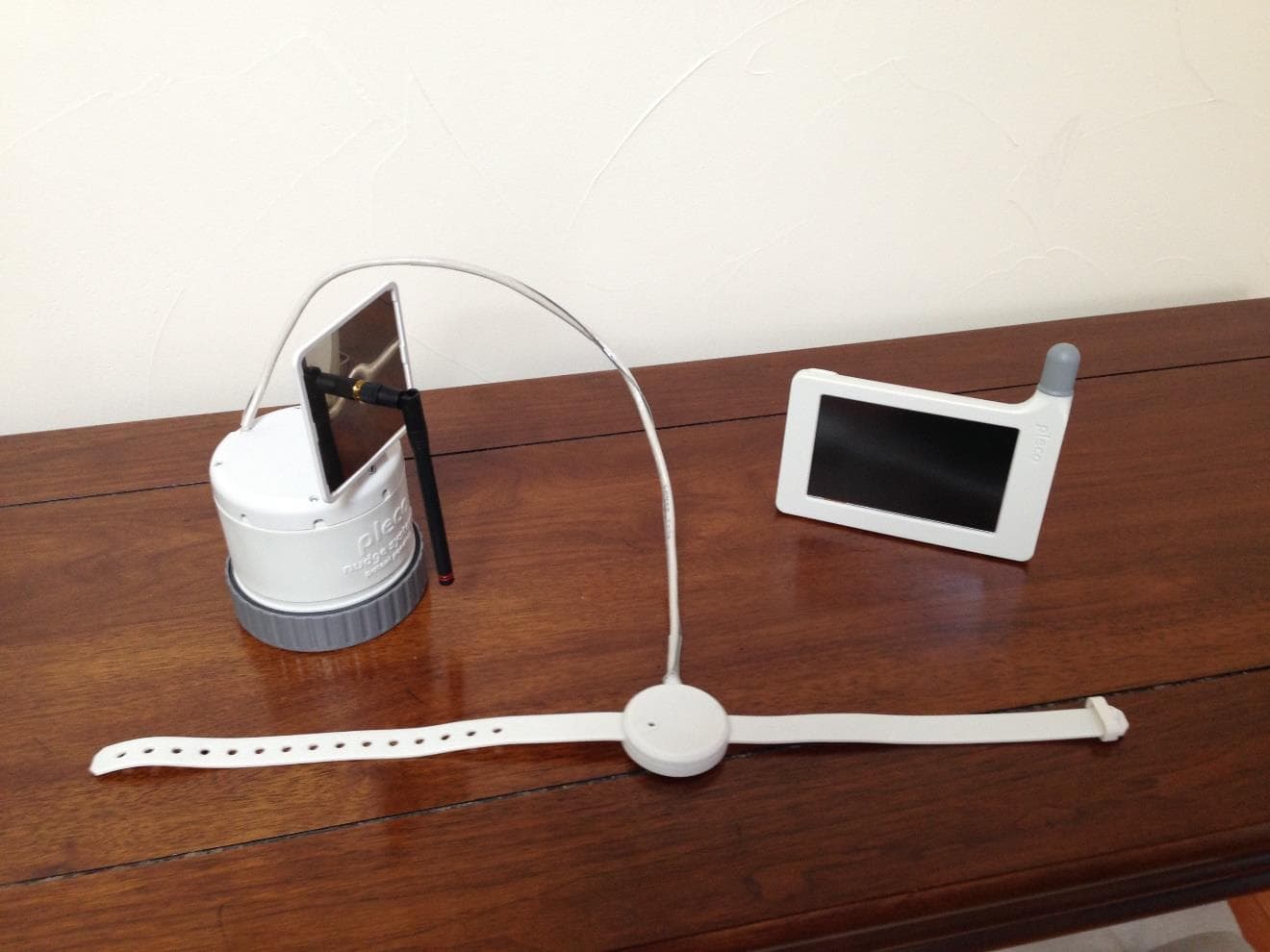
Mar 24, 2020Pleco sensor
Equipment Class
DSC - Part 15 Security/Remote Control Transmitter