2ATX7-JOLLYMODULEJolly module
Meteca SA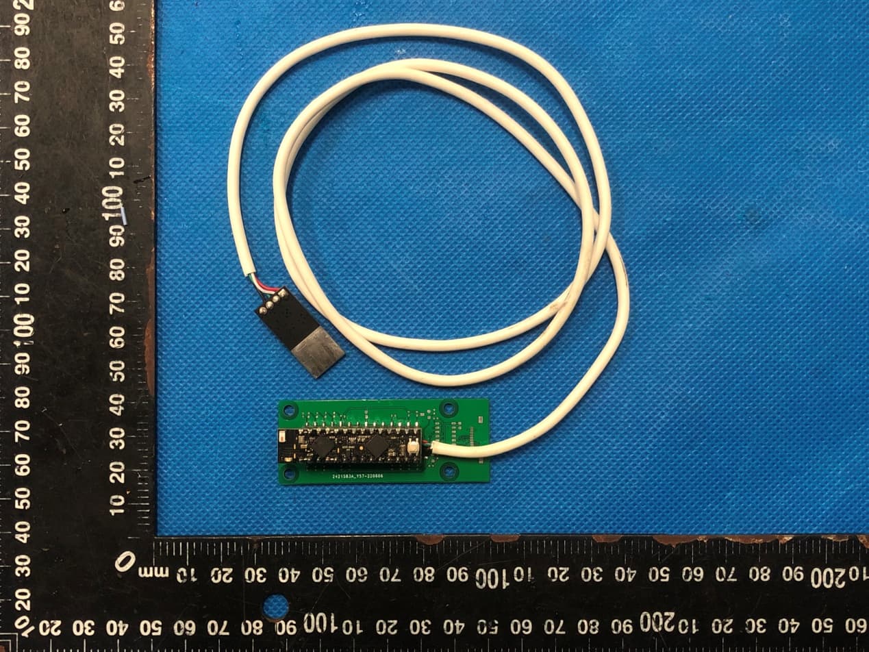
Click to zoom
Application Details
- Equipment Class
- DTS - Digital Transmission System
- Date of Grant
- Dec 14, 2022
- Application Purpose
- Original Equipment
- Date of Application
- Dec 14, 2022
- Equipment Note
- Jolly module
- Frequency Range
- 2412.00000000 - 2462.00000000
- Company
- Meteca SA
- Country
- Switzerland
Documents & Files
Document Text
Text extracted from the exhibit documents filed with the FCC. Open a document above to read the original.
Users Manual
Copyright © 2022 METECA SA. All rights reserved. Jolly Wi-Fi module User Manual Jolly module User Manual 2 Copyright © 2022 METECA SA. All rights reserved. 1.Revision History Revision number Revision date Summary of changes Authors 1.0 12/12/2022 Initial version D. Trimarchi FCC Warning Statement Changes or modifications not expressly approved by the party responsible for compliance could void the user’s authority to operate the equipment. This equipment has been tested and found to comply with the limits for a Class B digital device, pursuant to Part 15 of the FCC Rules. These limits are designed to provide reasonable protection against harmful interference in a residential installation. This equipment generates uses and can radiate radio frequency energy and, if not installed and used in accordance with the instructions, may cause harmful interference to radio communications. However, there is no guarantee that interference will not occur in a particular installation. If this equipment does cause harmful interference to radio or television reception, which can be determined by turning the equipment off and on, the user is encouraged to try to correct the interference by one or more of the following measures: ‐‐ Reorient or relocate the receiving antenna. ‐‐ Increase the separation between the equipment and receiver. ‐‐Connect the equipment into an outlet on a circuit different from that to which the receiver is connected. ‐‐ Consult the dealer or an experienced radio/TV technician for help. This device complies with part 15 of the FCC Rules. Operation is subject to the following two conditions: (1) This device may not cause harmful interference, and (2) this device must accept any interference received, including interference that may cause undesired operation. RF Exposure Statement To maintain compliance with FCC’s RF Exposure guidelines, this equipment should be installed and operated with minimum distance of 20cm the radiator your body. This device and its antenna(s) must not be co-located or operation in conjunction with any other antenna or transmitter. The information contained in this document is proprietary of Meteca SA and is confidential. It may not be disclosed to third parties nor used by the recipient for any purposes other than those explicitly allowed by Meteca SA. Without prejudice for the foregoing, the information contained in this document may be governed by more specific confidentiality agreements that have or will be entered into by Meteca SA and the recipient. This document is provided as is with no warranties whatsoever, including any warranty of merchantability, non-infringement, fitness for any particular purpose, or any warranty otherwise arising out of any proposal, specification or sample. All liability, including liability for infringement of any proprietary rights, relating to use of information in this document is disclaimed and excluded to the maximum extent allowed under the applicable law. No licenses express or implied to any intellectual property rights are granted herein. All trade names, trademarks and registered trademarks mentioned in this document are property of their respective owners and are hereby acknowledged. Information in this document, including url references, is subject to change without notice. Copyright © 2019 Meteca SA. All rights reserved. 3 Copyright © 2022 METECA SA. All rights reserved. 2.Index 1.Revision History ..................................................................................................................................................... 2 2.Index ....................................................................................................................................................................... 3 3.Introduction ............................................................................................................................................................ 4 4.Block Diagram ........................................................................................................................................................ 5 5.Schematic ............................................................................................................................................................... 6 6.Software ................................................................................................................................................................. 7 7. Module Warning Description.............................................................................................................................................. 9 Jolly module User Manual 4 Copyright © 2022 METECA SA. All rights reserved. 3.Introduction Jolly is a new electronic module for makers and Arduino UNO lovers. This Arduino Uno-compatible module has integrated Wi-Fi and has been designed to be the replacement of the Arduino UNO’s ATmega328P. It can be used as a replacement of the ATmega328P (as shown in the pictures below) or as a stand-alone module, placed on a breadboard or soldered in a new board. The reference markets/application areas are: prototyping, makers, IoT Example of how to use Jolly Module with ad Arduino UNO. 1)Take an Arduino UNO 2)Remove the ATmega328P 3)Replace it with the Jolly module For more info, please visit: Jolly DEV (jolly-dev.com) Jolly module User Manual 5 Copyright © 2022 METECA SA. All rights reserved. 4.Block Diagram The picture above shows the functional block diagram of the Jolly module. Jolly module User Manual 6 Copyright © 2022 METECA SA. All rights reserved. 5.Schematic Jolly module User Manual 7 Copyright © 2022 METECA SA. All rights reserved. 6.Software Since the Jolly module has been designed to replace the ATMega328P of the Arduino UNO, it allows us to preserve the full compatibility of the pinout, firmware, and hardware architecture of its predecessor. Therefore, a secondary microcontroller was inserted to allow the addition of Wi-Fi functionality, the E…
Text truncated - open the document above for the full version.
Cover Letter(s)
Meteca SA Agent Authorization Company: Meteca SA Address: Via alla Torre 2, 6850 Mendrisio Switzerland Product Name: Jolly module Model Number(s): Jolly module, JollyMod_v1 Product Description: Jolly module We authorize MiCOM Labs Inc., 575 Boulder Court, Pleasanton, California 94566, USA, to act on our behalf on all matters concerning the certification of above named equipment. We declare that MiCOM Labs Inc. is allowed to forward all information related to the approval and certification of equipment to the regulatory agencies as required and to discuss any issues concerning the approval application. Any and all acts carried out by MiCOM Labs on our behalf shall have the same effect as acts of our own. Signature: Date: Dec. 14, 2022 Name: Dario Trimarchi Title: Research & Development manager Company: Meteca SA
Cover Letter(s)
Meteca SA FCC Modular Approval Request Rev 3.0 Federal Communications Commission Equipment Authorization Division 7435 Oakland Mills Road Columbia, MD 21046 USA Date: Dec. 14, 2022 Subject; Modular Transmitter Application Company name: Meteca SA FCC ID: 2ATX7-JOLLYMODULE Dear Sir/Madam, This letter includes the FCC application requirements for Modular Transmitter Approval Request for;- FCC KDB 996369 D01 ‘Module Certification Guide v02; and FCC KDB 996369 D03 OEM Manual v01 In accordance with 47CFR 15.212 Modular Transmitters and KDB 996369 D01 ‘Module Equip Auth Guide v02’. FCC ID: 2ATX7-JOLLYMODULE has been examined against the following requirements. Requirement per 15.212 and KDB 996369 D01 Explanation from Grantee (do not write yes/no, but explain why product complies/how it is achieved) The radio elements must have the radio frequency circuitry shielded. Physical components and tuning capacitor(s) may be located external to the shield, but must be on the module assembly. No, the modular doesn't have its own shielding cover. The module must have buffered modulation/data inputs to ensure that the device will comply with Part 15 requirements with any type of input signal. Yes, The modular transmitter have buffered modulation/data inputs. The module must contain power supply regulation on the module. Yes, The modular transmitterhave its own power supply regulation. The module must contain a permanently attached antenna, or contain a unique antenna connector, and be marketed and operated only with specific antenna(s), per §§ 15.203, 15.204(b), 15.204(c), 15.212(a), 2.929(b). Yes, The modular transmitter comply with the antenna requirements of Section 15.203 and 15.204(c). The antenna either be permanently attached. The module must demonstrate compliance in a stand-alone configuration. Yes, The module can be configured independently and meets the requirements The module must be labeled with its permanently affixed FCC ID label, or use an electronic display (see KDB Publication 784748). Yes, The FCC ID on the product: 2ATX7- JOLLYMODULE The module must comply with all specific rules applicable to the transmitter, including all the conditions provided in the integration instructions by the grantee. Yes, The module complies fully with the operating requirements of Part 15 section as demonstrated in the test report. The module must comply with RF exposure requirements Yes, The modular transmitter complies with this requirement, please refer to RF exposure report. Meteca SA FCC Modular Approval Request Rev 3.0 Integration Instructions for host product manufacturers The following items are submitted in support of application for Modular Transmitter FCC ID as noted above as required by the FCC KDB 996369 D03 OEM Manual v01. These items are provided as integration instructions for host product manufacturers (e.g., OEM instruction manual) to use when integrating a module in a host product. Any requirements that are not applicable to the Module are as indicated below. Summary of requirements and Checklist. Refer to the KDB for description of the complete requirements; KDB Ref Sect Requirements of KDB 996369 D03 User Manual Page Number reference 2.2 List of applicable FCC rules P9 2.3 Summarize the specific operational use conditions P9 2.4 Limited module procedures P9 2.5 Trace antenna designs P9 2.6 RF exposure considerations P10 2.7 Antennas P10 2.8 Label and compliance information P11 2.9 Information on test modes and additional testing requirements P11 2.10 Additional testing, Part 15 Subpart B disclaimer P11 Name: Dario Trimarchi Date: Dec. 14, 2022 Title: Research & Development manager Signature of applicant:
Cover Letter(s)
Meteca SA Office of Engineering Technology Federal Communications Commission 7435 Oakland Mills Road Columbia, MD 21046 USA Date: Dec. 14, 2022 Subject; Request for Confidentiality FCC ID: 2ATX7-JOLLYMODULE To Whom It May Concern, Pursuant to the provisions of the Commission’s rules Title 47 Sections §0.457 and §0.459, we are requesting the Commission to withhold the following attachment(s) as confidential documents from public disclosure indefinitely. These documents contain detailed system and equipment descriptions and are considered as proprietary information in operation of the equipment. The public disclosure of these documents might be harmful to our company and would give competitors an unfair advantage in the market. Schematic Diagram Block Diagram Parts List Operational Description Tune-up Procedure In additional to above mentioned documents, in order to comply with the marketing regulations in Title 47 CFR §2.803 and the importation rules in Title 47 CFR §2.1204, while ensuring that business sensitive information remains confidential until the actual marketing of newly authorized devices, we request Short Term Confidentiality of the following attachment(s); External Photos Test Setup Photos Internal Photos User Manual For 45 days, pursuant to Public Notice DA 04-1705. OR For 180 days pursuantto KDB 726920 D01. It is our understanding that all measurement test reports, FCC ID label format and correspondence during the certification review process cannot be granted as confidential documents and this information will be available for public review once the grant of equipment authorization is issued. Sincerely, Signature: Name: Dario Trimarchi Title: Research & Development manager
Cover Letter(s)
Meteca SA Model Difference Declaration To Whom It May Concern, We, Meteca SA (Jolly module) ; Model Number: Jolly module, JollyMod_v1; All model’s the function, software and electric circuit are the same, only with product model named different. Test sample model: Jolly module. Please contact me if you have any question. Signature: Date: Dec. 14, 2022 Name: Dario Trimarchi Title: Research & Development manager
External Photos
Annex A External Photos Report No.:HK2211285364-E Page 1 of 1
ID Label/Location Info
FCC ID LABEL: Ca. 10mm x 5mm Label Location FCC ID: 2ATX7-JOLLYMODULE
Internal Photos
Annex B Internal Photos Report No.:HK2211285364-E Page 1 of 2 Antenna Report No.:HK2211285364-E Page 2 of 2
RF Exposure Info
MPE ESTIMATION FCC ID: 2ATX7-JOLLYMODULE 1,Limit for General Population/ Uncontrolled Exposures Frequency Power density (mW/ cm 2 ) Averaging time(minutes) 300MHz----1.5GHz F/1500 30 1.5GHz---100GHz 1.0 30 Note: F= Frequency in MHz 2, Estimation Result Mode Max PK Output power(dBm) Tune Up Power(dBm) Max Tune Up power(mW) Antenna Gain(dBi) Antenna Gain (numerical) MPE ( mW/cm²) WIFI 11.68 11±1(12) 15.85 0.5 1.12 0.00354 Note: Note: The estimation distance is 20cm Note: PK Output power= conducted power. Conducted power see the test report HK2211285364-E, antenna gain=0.5dBi when the minimum test separation distance is >20 cm, a distance of 20 cm is applied to determine RF Exposure test exclusion. The test exclusion threshold is 0.00354mW/cm² which is< 1.0mW/cm², RF Exposure testing is not required. -------The End-------
Test Report
2.4GHz Mini Antenna, SMTP/N 2450AT18A100 Detail Specification: Page 1 of 5 *Efficiency based on Johanson's standard evaluation board ±± ±± ±± www.johansontechnology.com 4001 Calle Tecate • Camarillo, CA 93012 • TEL 805.389.1166 FAX 805.389.1821 Ver. 3.0 2018 Johanson Technology, Inc. All Rights Reserved "High Frequency Ceramic Solutions" Part Number 7/9/2018 Avg. Rad Efficiency* Let us help you with the antenna design, optimization, and tuning! 2450AT18A100 2400 - 2500 76% General Specifications Frequency (MHz) 18 months max. -40 to +125°C -40 to +125°C 3000 Return Loss (dB) Impedance Input Power Storage Period Storage Temperature Operating Temperature Reel Quantity 50 Ω 2 Watts max. (CW) Johanson Technology, Inc. reserves the right to make design changes without notice. All sales are subject to Johanson Technology, Inc. terms and conditions. e.g. 2450AT18A100(E or S)100% Tin Packing Style Evaluation Board 2450AT18A100-EBSMA (see page 2&3 for details) Bulk (loose) T & R Suffix = E or S Suffix = E P/N Suffix Mechanical Dimensions In L 0.1260.0083.200.2 W 0.0630.0081.600.2 T 0.0511.30+.004/-.008 +0.1/-0.2 a 0.0200.0120.500.3 Terminal Configuration Function FEED NC No. 1 2 mm e.g. 2450AT18A100E e.g. 2450AT18A100SSuffix = S Part Number Explanation Peak Gain (dBi typ.) Average Gain (dBi typ.) 0.5 -0.5 9.5 min. ① ② L W a T Want the layout file? Request it at: www.johansontechnology.com/ask-a-question 2.4GHz Mini Antenna, SMTP/N 2450AT18A100 Detail Specification: Page 2 of 5 JTI P/N for Matching Circuit: Cap (1.0pF): 500R07S1R0BV4T Inductor (2.7nH): L-07C2N7SV6T Inductor (3.9nH): L-07C3N9SV6T www.johansontechnology.com 4001 Calle Tecate • Camarillo, CA 93012 • TEL 805.389.1166 FAX 805.389.1821 Ver. 3.0 2018 Johanson Technology, Inc. All Rights Reserved "High Frequency Ceramic Solutions" 7/9/2018 Mounting Considerations 1: Evaluation Board Johanson Technology, Inc. reserves the right to make design changes without notice. All sales are subject to Johanson Technology, Inc. terms and conditions. GND NO GND Units in mm ) ) 13.5mm 6.5mm 39.5mm 6.5mm 50Ω Feed Line Antenna 4mm ) Matching Component JTI P/Ns: L-14C2N7JV4 L-14C2N2JV4 * 2.6 4.2 1.6 1.9 0.4 2.7nH 1.0pF 3.9nH To order a pre-tuned 50Ω EVB with a female SMA connector click here: www.johansontechnology.com/request-a-sample Reference p/n: 2450AT18A100-EBSMA 2.4GHz Mini Antenna, SMTP/N 2450AT18A100 Detail Specification: Page 3 of 5 Return Loss with matching circuit @ +25CVSWR with matching circuit @ +25C and +125C www.johansontechnology.com 4001 Calle Tecate • Camarillo, CA 93012 • TEL 805.389.1166 FAX 805.389.1821 Ver. 3.0 2018 Johanson Technology, Inc. All Rights Reserved "High Frequency Ceramic Solutions" 7/9/2018 Mounting Considerations 1: Typical Electrical Performance (T=25°C) Johanson Technology, Inc. reserves the right to make design changes without notice. All sales are subject to Johanson Technology, Inc. terms and conditions. 2.4GHz Mini Antenna, SMT P/N 2450AT18A100 Detail Specification: Page 4 of 5 www.johansontechnology.com 4001 Calle Tecate • Camarillo, CA 93012 • TEL 805.389.1166 FAX 805.389.1821 Ver. 3.0 2018 Johanson Technology, Inc. All Rights Reserved "High Frequency Ceramic Solutions" 7/9/2018 Mounting Considerations 1: Antenna Performance Johanson Technology, Inc. reserves the right to make design changes without notice. All sales are subject to Johanson Technology, Inc. terms and conditions. Z X (0°) Y X (0°) Typical 2D radiation patterns @ 2.44GHz YZ-plane XZ-plane XY-plane Z (0°) Y XY cut @2.45GHz Vertical Horizontal XZ cut @2.45GHz Vertical Horizontal YZ cut @2.45GHz Vertical Horizontal 2.4GHz Mini Antenna, SMTP/N 2450AT18A100 Detail Specification: Page 5 of 5 www.johansontechnology.com 4001 Calle Tecate • Camarillo, CA 93012 • TEL 805.389.1166 FAX 805.389.1821 Ver. 3.0 2018 Johanson Technology, Inc. All Rights Reserved Johanson Technology, Inc. reserves the right to make design changes without notice. All sales are subject to Johanson Technology, Inc. terms and conditions. Soldering Information RoHS Compliance Packaging information For layout review contact our Applications Team at: "High Frequency Ceramic Solutions" Antenna tuning, optimization, and validation services: For more antennas and to download measured S-parameters, go to: MSL Info 7/9/2018 www.johansontechnology.com/ipc-antenna-services www.johansontechnology.com/antennas www.johansontechnology.com/ipcsoldering-profile www.johansontechnology.com/msl-rating www.johansontechnology.com/tape-reel-packaging www.johansontechnology.com/ask-a -question www.johansontechnology.com/rohs-compliance Need help designing the antenna in? Use our antenna design services! www.johansontechnology.com/ipc-antenna-services We provide 2 free layout reviews and if you need us to tune and characterize the antenna on your product (inside anechoic chamber) we can do that too. Small lab fee may apply for the latter.
Test Report
Page 1 of 60 Report No.: HK2211285364-E FCC TEST REPORT Test report On Behalf of Meteca SA For Jolly module Model No.: Jolly module, JollyMod_v1 FCC ID: 2ATX7-JOLLYMODULE Prepared For : Meteca SA Via alla Torre 2, 6850 Mendrisio Switzerland Prepared By : Shenzhen HUAK Testing Technology Co., Ltd. 1-2/F., Building B2, Junfeng Zhongcheng Zhizao Innovation Park, Heping, Fuhai Street, Bao’an District, Shenzhen, Guangdong, China Date of Test: Nov. 25, 2022 ~ Dec. 02, 2022 Date of Report: Dec. 02, 2022 Report Number: HK2211285364-E Applican Address Manufa c Address Product Trade M a Product n Model an Standard This publ the Shen source o f and will n reproduc Date of T Date (s) o Date of Is Te s t R e su nt’s name .. .................. cture's Nam .................. descriptio ark: name ........... nd/or type re ds .............. lication may zhen HUAK f the materi not assume ed material Test ............ of performan ssue ........... ult ............... Te s Te c Aut TES ................: ................: me .............: ................: n .................. : eference .: ................: y be reprod K Testing Te al. Shenzhe liability for due to its p .................. nce of tests .................. .................. sting Engine chnical Man thorized Sig ST RESU Meteca SA Via alla To Meteca SA Via alla To Jolly dev. Jolly mod Jolly mod FCC Rul e ANSI C63 uced in who echnology C en HUAK Te damages re placement a .............. : s ............. : .............. : .............. : eer : nager : gnatory : Page 2 of ULT CER A orre 2, 6850 A orre 2, 6850 ule ule, JollyM o es and Regu 3.10: 2013 ole or in par Co., Ltd. is a esting Tech esulting from and context Nov. 25, 20 Dec. 02, 20 Pass 60 RTIFICAT 0 Mendrisio 0 Mendrisio od_v1 ulations Par rt for non-co acknowledg nology Co., m the reade t. 022 ~ Dec. 0 022 (Gary Qi a (Eden H u (Jason Zho Repor TION Switzerlan Switzerlan rt 15 Subpa ommercial p ged as copy , Ltd. takes er's interpre 2, 2022 an) u) ou) rt No.: HK221 d d art C Sectio purposes as yright owner no respons etation of the 11285364-E n 15.247 s long as r and sibility for e Page 3 of 60 Report No.: HK2211285364-E TABLE OF CONTENTS 1. TEST RESULT SUMMARY ........................................................................ 5 1.1. TEST PROCEDURES AND RESULTS ............................................................................................... 5 1.2. INFORMATION OF THE TEST LABORATORY ................................................................................ 5 1.3. MEASUREMENT UNCERTAINTY ..................................................................................................... 6 2. EUT DESCRIPTION ................................................................................... 7 2.1. GENERAL DESCRIPTION OF EUT ................................................................................................... 7 2.2. CARRIER FREQUENCY OF CHANNELS .......................................................................................... 8 2.3. OPERATION OF EUT DURING TESTING .......................................................................................... 8 2.4. DESCRIPTION OF TEST SETUP ....................................................................................................... 9 3. GENERA INFORMATION ........................................................................ 10 3.1. TEST ENVIRONMENT AND MODE ................................................................................................. 10 3.2. DESCRIPTION OF SUPPORT UNITS .............................................................................................. 11 4. TEST RESULTS AND MEASUREMENT DATA ...................................... 12 4.1. CONDUCTED EMISSION ................................................................................................................. 12 4.2. TEST RESULT .................................................................................................................................. 14 4.3. MAXIMUM CONDUCTED OUTPUT POWER ................................................................................... 16 4.4. EMISSION BANDWIDTH .................................................................................................................. 18 4.5. POWER SPECTRAL DENSITY ........................................................................................................ 23 4.6. CONDUCTED BAND EDGE AND SPURIOUS EMISSION MEASUREMENT ................................. 28 4.7. RADIATED SPURIOUS EMISSION MEASUREMENT .................................................................... 36 5. ANTENNA REQUIREMENT ..................................................................... 57 6. PHOTOGRAPH OF TEST ........................................................................ 58 7. PHOTOS OF THE EUT ............................................................................ 60 Page 4 of 60 Report No.: HK2211285364-E ** Modified History ** Revision Description Issued Data Remark Revision 1.0 Initial Test Report Release Dec. 02, 2022 Jason Zhou Page 5 of 60 Report No.: HK2211285364-E 1. TEST RESULT SUMMARY 1.1. TEST PROCEDURES AND RESULTS Requirement CFR 47 Section Result Antenna requirement §15.203/§15.247(b)(4) PASS AC Power Line Conducted Emission §15.207 PASS Conducted Peak Output Power §15.247(b)(3) PASS 6dB Emission Bandwidth §15.247(a)(2) PASS Power Spectral Density §15.247(e) PASS Band Edge §15.247(d) PASS Spurious Emission §15.205/§15.209 PASS Note: 1. PASS: Test item meets the requirement. 2. Fail: Test item does not meet the requirement. 3. N/A: Test case does not apply to the test object. 4. The test result judgment is decided by the limit of test standard. 1.2. INFORMATION OF THE TEST LABORATORY Shenzhen HUAK Testing Technology Co., Ltd. Add.: 1-2/F., Building B2, Junfeng Zhongcheng Zhizao Innovation Park, Heping, Fuhai Street, Bao’an District, Shenzhen, Guangdong, China Testing Laboratory Authorization: A2L…
Text truncated - open the document above for the full version.
Test Setup Photos
Report No.: HK2211285364-E Radiated Emissions Report No.: HK2211285364-E Conducted Emission
Contact Information
Applicant
Dario Trimarchi(Research & Development manager)
Technical Contact
Test Firm
Shenzhen HUAK Testing Technology Co., Ltd.Jason Zhou
[email protected]86-755-23029901
Technical Specifications
| # | Rule Parts | Frequency Range | Power Output |
|---|---|---|---|
| 1 | 15C | 2.41 GHz - 2.46 GHz | 14.72 mW |