2ATXJ-AKCC25Fixed industrial refrigeration controller with Bluetooth Low Energy (BLE)
Danfoss A/S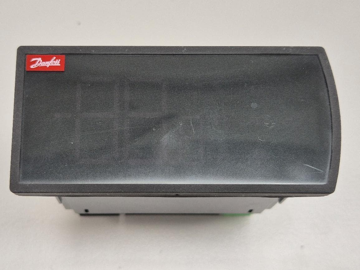
Click to zoom
Application Details
- Equipment Class
- DTS - Digital Transmission System
- Date of Grant
- Jun 23, 2026
- Application Purpose
- Original Equipment
- Equipment Note
- Fixed industrial refrigeration controller with Bluetooth Low Energy (BLE)
- Frequency Range
- 2402.00000000 - 2480.00000000
- Company
- Danfoss A/S
- Country
- Denmark
Documents & Files
Document Text
Text extracted from the exhibit documents filed with the FCC. Open a document above to read the original.
Users Manual
© Danfoss Climate Solutions 2026.01 Literature no. AP550816080557en-000101 Page 1 of 3 Climate Solutions product notification Market release of AK-CC25 Pro BT case controllers For internal use only Information Action required Segment ☐ ☒ Technical Commercial ☐ ☐ ☒ ☐ FYI only Inform customers (See “Key message to Customers”) Inform customers (customer letter attached) Other ☐ ☒ ☐ ☐ ☐ ☐ ☐ ☐ Air conditioning Food retail Industrial refrigeration Commercial refrigeration HX Heat exchangers Industrial Automation District Heating Building Solutions Products AK-CC25 Pro Summary Danfoss is expanding the release of the new ADAP-KOOL® AK-CC25 case controller family. We are now introducing the Bluetooth-enabled AK-CC25 Pro BT, following the initial launch of the AK-CC25 Pro in December 2025. The AK-CC25 series will gradually replace the current EKC 202 and AK-CC 2xx controllers. AK-CC25 Pro highlights • New modern design and improved User Experience o White LED display and backlit capacitive touch buttons to only show the relevant UI elements o Built-in BLE for connectivity with AK-CC Connect mobile app for fast and easy service & commissioning o New and improved functions in the mobile app: FW update, performance dashboards, Wizard for guided field installation and commissioning • Best-in class application coverage in a single variant o Support for variable speed compressors, dual circuits, dual compressors o Full parameter MT/LT switch for optimized performance o Fully flexible I/O configuration for customized applications • Food safety & energy efficiency o Robust design for reliable operation with minimum downtime o VSC enables MTR for optimal temperature in a display cabinet • Improved connectivity and monitoring: o Modbus RS-485 built-in o BLE built-in • AK-CC25 Pro is positioned as the “entry-level” Food Retail case controller, targeted for TXV application with plug-in focus • Replaces legacy, non-competitive AK-CC 2xx series and EKC 202 series © Danfoss Climate Solutions 2026.01 Literature no. AP550816080557en-000101 Page 2 of 3 Launch Timing December 2025: Market release for sales of AK-CC25 Pro for Europe and Turkey. January 2026: Market release for sales of AK-CC25 Pro BT. February 2026: Extended global sales release, subject to local compliance and approvals. Promotion wave: • Customer engagement tool update • Product webpage update + web banner • Webnews • Newsletter • SoMe ambassador (organic) For more details visit Launch site: AK-CC25 Approvals scope General/safety (LVD/EMC/RoHS) • CE/EN complete • UL recognized – USA + Canada in process • C-tick (RCM) – Australia + NZ pending • UA – Ukraine pending Bluetooth/radio: • CE (RED) complete • FCC – USA in process • C-tick (RCM) – Australia (ACMA) + NZ (RSM) pending • Ramatel - Argentina pending • Anatel – Brasil pending • IFT –Mexico pending • Subtel- Chile pending • IC (ISED) – Canada pending • UA – Ukraine pending • TBD: CMIIT – China pending Availability & Ordering The current release of AK-CC25 Pro and Pro BT is global but subject to local compliance certification. The product store will reflect this. Description Code no. Availability in CDC AK-CC25 Pro, Single pack 084B4022 Week 50, 2025 AK-CC25 Pro, Industrial pack (27 units) 084B4122 Coming soon AK-CC25 Pro BT, Single pack 084B4023 01.02.2026 AK-CC25 Pro BT, Industrial pack (27 units) 084B4123 Coming soon Connectors kit for AK-CC25 Pro, Industrial pack (81 units) 084B4714 Coming soon Interface cable AK-CC25 - KoolKey 2.1, Single pack 080N0334 Week 50, 2025 KoolKey 2.1 (PV04), Single pack 080N0020 Week 50, 2025 Available Technical Documentation The following AK-CC25 Pro documents are released to DAM: BC515532816014en-000102.pdf User Guide AU531131049269en-000101.pdf Modbus Interface description AN513629347022en-000101.pdf Installation Guide AI539523026164en-000101.pdf Data Sheet © Danfoss Climate Solutions 2026.01 Literature no. AP550816080557en-000101 Page 3 of 3 EKC/AK-CC 2xx Phase out With the launch of AK-CC25, we have started phasing out EKC 202 and AK-CC 2xx controllers. Effective ramp-down planning is essential to avoid excess inventory and ensure a smooth market transition. Please focus on: Informing customers about AK-CC25 Supporting their migration from legacy controllers Our goal is to end sales of the existing generation by the end of 2026, following the full launch of AK-CC25 and a reasonable transition period. Expected phase-out timeline (subject to change as we progress): - May 2025: Inform Customers of portfolio changes, phase-out and ask for future outlook/demand - June 2025 onwards: Collect customer plans regarding transition to AK-CC25 - Q4 2025: Official phase-out starts - Jan 2026 onwards: Expected gradual price increases for outgoing generation - June 2026: Last time orders for outgoing generation - December 2026: Last deliveries of outgoing generation The goal is to stop sales of existing generation by the end of 2026, once the AK-CC25 program is fully launched, and a reasonable transition period is given. A dedicated Product notification will be issued shortly, and more details will follow. Online support You can access and download detailed product information through the Partner Portal/Product Data Tool: partner.danfoss.com Contact Global Customer Product Support Link to Salesforce “New Case Creation” https://danfoss.my.salesforce.com/500/e?retURL=/500/o&RecordType=012C0000000p9BO&ent=Case Visit our new Product Support Site Global Product Support - Home (sharepoint.com)
Users Manual
Installation Guide Case/room controller Type AK-CC25 Ultra 084R6218 AN552917836697en-000101 © Danfoss | Climate Solutions | 2026.04 AN552917836697en-000101 | 1 85 40 29 71 70 6.2 Danfoss80G8717 Identification & Dimensions (in mm) Panel mounting AK-CC25 Ultra : 084B4025 Display operation The values will be shown with three digits, and with a setting you can determine whether the temperature is to be shown in °C or in °F To guarantee IP65 protection, the controller must be fixated with the mounting brackets pushed tight on to the mounting plate (Force: min. 245 nm per bracket). Maximum deviation between the edges of the rectangular mounting hole from flat surface: ≤ 0.5 mm (0,02 in) Maximum roughness of the surface where the gasket is applied: ≤ 120 μm. IconsNameDescription ECO modeLights up when in night/ECO mode CoolingLights up when cooling FanLights when evaporator fans are running Navigation buttons BackNavigates back to previous menu Up Navigates up in menu structure Increase value when in setting mode Down Navigates down in menu structure Increase value when in setting mode Info menuNavigates to the controller info menu IconsNameDescription Direct action buttons SET Short press: Change thermostat setpoint Long press: Navigate to parameter menu Alarm Short press: Navigates to list of active alarms Long press: Manual reset of alarms Long press while in menu: Reset of alarms LightLong press: Switches light status DefrostLong press: Start/stop of a defrost cycles Bluetooth Long press: Initiate/Terminate Bluetooth connection Star Not in use CodeDescription ErrThe temperature cannot be displayed due to a sensor error ---Three dashes shown in top - Max. value range has been reached --- Three dashes shown in middle – Parameter is protected by main switch and cannot be changed until “r12 Main switch” is set in OFF position --- Three dashes shown in bottom - Min. value range has been reached Loc The button operation is locked. Unlock by swiping from left to right across the buttons placed in the middle UnLThe button operation is unlocked The allowed thickness of the mounting plate are min. 0.8 mm (0.03 inch) and max. 18 mm (0.70 inch). Danf oss 80G8765 PSA higher-level access code is required for performing action FanA case cleaning procedure is ongoing. The fans are running OFF r12 Main switch has been set in OFF position. A case cleaning procedure is ongoing – All outputs are in standby mode SEr r12 Main switch has been set in service mode position for override of outputs dDefrost is in progress FAC The reset to OEM factory procedure has been initiated – select Yes to confirm or No to abort OP1Operation mode 1 has been selected OP2Operation mode 2 has been selected © Danfoss | Climate Solutions | 2026.04 2 | AN552917836697en-000101 1234 DO1DO2 181920 DI2 AO1 DI1 AI4 S5DI2 21222324 A+B- -+s Modbus P 0 – 10 V Danfos s 80G8 79 4 151617 AI2AI3 S3S4 100 – 240 V AC 567 DO4 10111289 DO3-AKV 1314 AI1 S2 Option card 25262728 AIAO5V * PrincipleWiring diagram *Note: Each AI/DI/AO signal must have a separate ground wire. Set access codes at first power up At first power up, the user will be prompted to set an access code, please refer to the screen flow below: Authentication The user will always be prompted for selecting a user level (L1/L2/L3) and the corresponding access code, when performing an action that requires a certain access level - please refer to the example below. If access codes have not been set, the display will flash between the two first screens “SEt” and “PS” to indicate that the access codes must be set. By pressing the “SET” key, the access code values can be set in screen 3. Be aware, all access codes will be set at this value. Once the access codes are set, the display returns to the normal temperature read out. User performs a long press on SET to enter parameter menu. The user set the value of the corresponding access code and presses SET. The display indicates that authentication is required by showing “PS” for 2 sec. If the provided access code is correct the action that initiated the authentication is carried out. The user selects the access level and presses SET. Danf oss 80G8793 P S2 S4 S3 AKV S5 © Danfoss | Climate Solutions | 2026.04 AN552917836697en-000101 | 3 Data communication It is important that the installation of data communication cable is performed correctly with sufficient distance to high voltage cables. For more information, refer the Communications Design Guide. Max. 10 The following controllers can be connected in this way: EKC 204A, AK-CC 210, AK-CC 250, AK-CC 450, AK-CC 550 and AK-CC55. Refrigeration is resumed at the same time when all controllers have terminated defrost. Coordinated defrost via cable connections A+ B- A+ B- Danfos s 80G8 716 Option card Modbus 21 22 2324 A+ B- 18 19 2015 16 1713 14 Electric noise Cables for sensors, low voltage DI inputs and data communication must be kept separate from other electric cables: - Use separate cable trays - Keep a distance between cables of at least 10 cm - Long cables at the low voltage DI input should be avoided Installation considerations Accidental damage, poor installation, or site conditions, can give rise to malfunctions of the control system, and ultimately lead to a plant breakdown. Every possible safeguard is incorporated into our products to prevent this. However, a wrong installation could still present problems. Electronic controls are no substitute for normal, good engineering practice. Danfoss will not be responsible for any goods, or plant components, damaged as a result of the above defects. It is the installer's responsibility to check the installation thoroughly, and to fit the necessary safety devices. Special reference is made to the necessity of signals to the controller when the compressor is stopped and to the need of liquid receivers before the compressors. Your local Danfoss agent will be pleased to assist with further advice, etc. For security reasons the connection terminals and…
Text truncated - open the document above for the full version.
Users Manual
Installation Guide Case/room controller Type AK-CC25 Pro and AK-CC25 Pro BT 084R6217 AN513629347022en-000201 © Danfoss | Climate Solutions | 2026.01 AN513629347022en-000201 | 1 85 40 29 71 70 6.2 Danfoss80G8717 Identification & Dimensions (in mm) Panel mounting AK-CC25 Pro : 084B4022 AK-CC25 Pro BT : 084B4023 Display operation The values will be shown with three digits, and with a setting you can determine whether the temperature is to be shown in °C or in °F To guarantee IP65 protection, the controller must be fixated with the mounting brackets pushed tight on to the mounting plate (Force: min. 245 nm per bracket). Maximum deviation between the edges of the rectangular mounting hole from flat surface: ≤ 0.5 mm (0,02 in) Maximum roughness of the surface where the gasket is applied: ≤ 120 μm. IconsNameDescription ECO modeLights up when in night/ECO mode CoolingLights up when cooling FanLights when evaporator fans are running Navigation buttons BackNavigates back to previous menu Up Navigates up in menu structure Increase value when in setting mode Down Navigates down in menu structure Increase value when in setting mode Info menuNavigates to the controller info menu IconsNameDescription Direct action buttons SET Short press: Change thermostat setpoint Long press: Navigate to parameter menu Alarm Short press: Navigates to list of active alarms Long press: Manual reset of alarms Long press while in menu: Reset of alarms LightLong press: Switches light status DefrostLong press: Start/stop of a defrost cycles Bluetooth Long press: Initiate/Terminate Bluetooth connection StarNot in use CodeDescription ErrThe temperature cannot be displayed due to a sensor error ---Three dashes shown in top - Max. value range has been reached --- Three dashes shown in middle – Parameter is protected by main switch and cannot be changed until “r12 Main switch” is set in OFF position --- Three dashes shown in bottom - Min. value range has been reached Loc The button operation is locked. Unlock by swiping from left to right across the buttons placed in the middle UnLThe button operation is unlocked The allowed thickness of the mounting plate are min. 0.8 mm (0.03 inch) and max. 18 mm (0.70 inch). Danf oss 80G8765 PSA higher-level access code is required for performing action FanA case cleaning procedure is ongoing. The fans are running OFF r12 Main switch has been set in OFF position. A case cleaning procedure is ongoing – All outputs are in standby mode SEr r12 Main switch has been set in service mode position for override of outputs dDefrost is in progress FAC The reset to OEM factory procedure has been initiated – select Yes to confirm or No to abort OP1Operation mode 1 has been selected OP2Operation mode 2 has been selected © Danfoss | Climate Solutions | 2026.01 2 | AN513629347022en-000201 Principle Application 5-8 (single circuit) Application 5-8 (dual circuits) Application 1-4 Application 1-4 MM S4 S3 S5 Frequency 0 – 200 Hz Danf oss 80G8703 S3 LLSV S5 MM S4 Danf oss 80G8705 MM S4 S3 S5 Danf oss 80G870 4 MM S5 Danf oss 80G870 6 MM S5 S3 S4 Set access codes at first power up At first power up, the user will be prompted to set an access code, please refer to the screen flow below: Authentication The user will always be prompted for selecting a user level (L1/L2/L3) and the corresponding access code, when performing an action that requires a certain access level - please refer to the example below. If access codes have not been set, the display will flash between the two first screens “SEt” and “PS” to indicate that the access codes must be set. By pressing the “SET” key, the access code values can be set in screen 3. Be aware, all access codes will be set at this value. Once the access codes are set, the display returns to the normal temperature read out. User performs a long press on SET to enter parameter menu. The user set the value of the corresponding access code and presses SET. The display indicates that authentication is required by showing “PS” for 2 sec. If the provided access code is correct the action that initiated the authentication is carried out. The user selects the access level and presses SET. © Danfoss | Climate Solutions | 2026.01 AN513629347022en-000201 | 3 Wiring Application 1 Application 3 Application 7 Application 9 Application 5 Application 4 Application 2 Application 8 Application 6 1 1234 DO1DO2 Option card 181920 DI2 AO1 DI1 AI4 DI1DI2 21222324 A+B- Modbus 0 – 200 Hz Danfos s 80G8 70 7 151617 AI2AI3 S4S5 120 – 230 V AC 567 DO4 10111289 DO3 1314 AI1 S3 * 2 1234 DO1DO2 Option card 181920 DI2 AO1 DI1 AI4 DI1DI2 21222324 A+B- Modbus 0 – 200 Hz Danfos s 80G8 70 8 151617 AI2AI3 S4S5 120 – 230 V AC 567 DO4 10111289 DO3 1314 AI1 S3 3 1234 DO1DO2 Option card 181920 DI2 AO1 DI1 AI4 DI1DI2 21222324 A+B- Modbus 0 – 200 Hz Danfos s 80G8 70 9 151617 AI2AI3 S4S5 120 – 230 V AC 567 DO4 10111289 DO3 1314 AI1 S3 4 1234 DO1DO2 Option card 181920 DI2 AO1 DI1 AI4 DI1DI2 21222324 A+B- Modbus 0 – 200 Hz Danfos s 80G8 71 0 151617 AI2AI3 S4S5 120 – 230 V AC 567 DO4 10111289 DO3 1314 AI1 S3 1 5 1234 DO1DO2 Option card 181920 DI2 AO1 DI1 AI4 DI1DI2 21222324 A+B- Modbus Danfos s 80G8 71 1 151617 AI2AI3 S4S5 120 – 230 V AC 567 DO4 10111289 DO3 1314 AI1 S3 2 1 6 1234 DO1DO2 Option card 181920 DI2 AO1 DI1 AI4 DI1DI2 21222324 A+B- Modbus Danfos s 80G8 71 2 151617 AI2AI3 S4S5 120 – 230 V AC 567 DO4 10111289 DO3 1314 AI1 S3 2 1 7 1234 DO1DO2 Option card 181920 DI2 AO1 DI1 AI4 DI1DI2 21222324 A+B- Modbus Danfos s 80G8 71 3 151617 AI2AI3 S4S5 120 – 230 V AC 567 DO4 10111289 DO3 1314 AI1 S3 2 1 8 1234 DO1DO2 Option card 181920 DI2 AO1 DI1 AI4 DI1DI2 21222324 A+B- Modbus Danfos s 80G8 71 4 151617 AI2AI3 S4S5 120 – 230 V AC 567 DO4 10111289 DO3 1314 AI1 S3 2 9 1234 DO1DO2 Option card 181920 DI2 AO1 DI1 AI4 21222324 A+B- Modbus Danfos s 80G8 71 5 151617 AI2AI3 120 – 230 V AC 567 DO4 10111289 DO3 1314 AI1 *Note: Each AI/DI/AO signal must have a separate ground wire. © Danfoss | Climate Solutions | 2026.01 4 | AN513629347…
Text truncated - open the document above for the full version.
Users Manual
User Guide Case/room controller (TXV) AK-CC25 Pro and AK-CC25 Pro BT SW Ver. 1.3x For refrigeration appliances and cold storage rooms Contents Introduction ......................................................................................3 Application ......................................................................................3 Hardware features.........................................................................3 Features and functions................................................................3 Principle ......................................................................................4 Application coverage ...................................................................4 Operation ......................................................................................8 User interface ......................................................................................8 Display ......................................................................................8 Display modes ................................................................................8 Display operation and related settings .................................9 Operation via AK-CC Connect App .......................................15 Commissioning .................................................................................17 Protection of configuration .....................................................17 Quick setup ...................................................................................17 Functions and features ..............................................................19 Applications ....................................................................................19 Wiring diagrams ..........................................................................23 Special wiring details .................................................................24 Technical data...............................................................................26 Functions ....................................................................................28 Main switch ...................................................................................28 Temperature control ..................................................................28 Thermostat temperature ...............................................28 Thermostat control ..........................................................29 Emergency control ..........................................................30 Night setback ....................................................................30 Frost protection ................................................................31 Temperature pulldown – quick freeze .....................31 Heating thermostat .........................................................32 Melt function .....................................................................33 Food temperature and product sensor ...............................33 Temperature alarm monitoring .............................................33 Switch operation mode – Plugin for MT and LT ...............33 Compressor control ....................................................................34 ON/OFF control of a single compressor...................34 ON/OFF control of two compressors - single refrigeration circuit .............................................34 ON/OFF control of two compressors – Independent refrigeration circuits ............................35 Variable speed compressor ..........................................36 Compressor anti cycle timers ......................................38 Compressor safety monitoring ...................................38 Defrost control .............................................................................40 Defrost start .......................................................................40 Defrost sequence .............................................................41 Defrost method ................................................................42 Defrost stop........................................................................44 Co-ordinated defrost ......................................................45 Fan control during defrost ............................................46 Rail heat control during defrost ..................................47 Drain heater control ........................................................47 Fan control ....................................................................................48 Rail heat control ...........................................................................48 Timer controlled ...............................................................48 Dew point controlled .....................................................49 Light control..................................................................................50 Condenser ....................................................................................50 Safety monitoring ............................................................50 Condenser fan control....................................................51 Door function ...............................................................................51 Leak detection ..............................................................................52 Case cleaning ................................................................................52 Case shutdown ............................................................................52 Power up delay ............................................................................53 Display control .............................................................................53 Real-time clock .............................................................................53 Master control overrides ..........................................................53 Performance monitoring ..........................................................54 Number of high temp. alarm…
Text truncated - open the document above for the full version.
Internal Photos
Antenna
Test Setup Photos
Figure 1 - AC Line Power Conducted Emissions Figure 2 - Radiated Emission (30 MHz to 1GHz) Figure 3 - Radiated Emission (1GHz to 18GHz) Figure 4 - Radiated Emission (18GHz to 26GHz) Figure 5 –RF Conducted Test Setup Figure 6 - Test Setup- DUT
Test Report
ABRACON IS ISO9001-2015 CERTIFIED Hidden Creek Ln Spicewood TX 78669 5101 Phone: 512-371-6159 | Fax: 512-351-8858 REVISED: For terms and conditions of sales, please visit: www.abracon.com OnBoard 2.4 GHz Mini SMD - Antenna PRO-OB-607 9.90 x 4.30 x 2.00 mm RoHS/RoHS II Compliant MSL Level = 1 Request Samples Check Inventory Features • Ultra Compact • Low Profile of 2 mm • Mixed Linear Polarization • Peak Gain of 1 dBi • Surface Mounted • Durable-Shelf life of up to 10 years Applications • Wi-Fi/BT/BLE/ZigBee/ISM Applications • IoT, M2M o Industrial o Infrastructure o Medical • Remote Technology / Monitoring • Network Devices • Consumer Tracking • Smart Home • Smart Wearables Product Image ABRACON IS ISO9001-2015 CERTIFIED Hidden Creek Ln Spicewood TX 78669 5101 Phone: 512-371-6159 | Fax: 512-351-8858 REVISED: For terms and conditions of sales, please visit: www.abracon.com OnBoard 2.4 GHz Mini SMD - Antenna PRO-OB-607 9.90 x 4.30 x 2.00 mm RoHS/RoHS II Compliant MSL Level = 1 Request Samples Check Inventory Electrical Specification Note: All measurements were conducted on the evaluation board in free space. Performance will vary depending on the ground plane, application, and environment. Mechanical Specification Environmental Specification Parameter Specification Unit Operating Frequency 2400 - 2500 MHz Return Loss ˂ -7.3 dB Polarization Mixed Linear - Peak Gain 1 dBi Efficiency >-3.9 (41) dB (%) Impedance 50 Ω Parameter Specification Antenna Dimension 9.90 x 4.30 x 2.00 mm Evaluation board Dimension 48 x 18 mm Mounting Type Surface Mount Parameter Specification Operating Temperature -40°C to +125°C Storage Temperature Maximum Temperature 400°C RoHS Compliance Yes Compliant with EU directive 2011/65/EU and 2015/863 Shelf life 10 years MSL Level 1, unlimited ABRACON IS ISO9001-2015 CERTIFIED Hidden Creek Ln Spicewood TX 78669 5101 Phone: 512-371-6159 | Fax: 512-351-8858 REVISED: For terms and conditions of sales, please visit: www.abracon.com OnBoard 2.4 GHz Mini SMD - Antenna PRO-OB-607 9.90 x 4.30 x 2.00 mm RoHS/RoHS II Compliant MSL Level = 1 Request Samples Check Inventory Product Dimensions Unit : mm Antenna pins and keep-out block Unit : mm ABRACON IS ISO9001-2015 CERTIFIED Hidden Creek Ln Spicewood TX 78669 5101 Phone: 512-371-6159 | Fax: 512-351-8858 REVISED: For terms and conditions of sales, please visit: www.abracon.com OnBoard 2.4 GHz Mini SMD - Antenna PRO-OB-607 9.90 x 4.30 x 2.00 mm RoHS/RoHS II Compliant MSL Level = 1 Request Samples Check Inventory PCB layout and antenna pin numbering The antenna uses PIFA technology and should thus be mounted on a ground plane. If there are several layers in the PCB, there is an advantage to add vias for smooth interconnection of the ground areas to avoid splits in the ground plane. It is also important that there is a ground clearance around the NC pads and the RF feed pad, through all layers of the PCB. It is recommended to implement a matching network to optimize the antenna impedance in your application. The components can be positioned under the antenna. See recommendations in the figures below. Pin configuration PCB Layout (from evaluation board) Top Layer Bottom Layer (Clearance through all layer) Unit: mm ABRACON IS ISO9001-2015 CERTIFIED Hidden Creek Ln Spicewood TX 78669 5101 Phone: 512-371-6159 | Fax: 512-351-8858 REVISED: For terms and conditions of sales, please visit: www.abracon.com OnBoard 2.4 GHz Mini SMD - Antenna PRO-OB-607 9.90 x 4.30 x 2.00 mm RoHS/RoHS II Compliant MSL Level = 1 Request Samples Check Inventory Measurement Setup The antenna measurements were all done in free space with the SMD 2400 Mini evaluation board (PRO-EB-609) that has a PCB size of 48 x 18 mm. ABRACON IS ISO9001-2015 CERTIFIED Hidden Creek Ln Spicewood TX 78669 5101 Phone: 512-371-6159 | Fax: 512-351-8858 REVISED: For terms and conditions of sales, please visit: www.abracon.com OnBoard 2.4 GHz Mini SMD - Antenna PRO-OB-607 9.90 x 4.30 x 2.00 mm RoHS/RoHS II Compliant MSL Level = 1 Request Samples Check Inventory Reflection Characteristics – Return Loss Total Radiation Efficiency Maximum Radiation Gain ABRACON IS ISO9001-2015 CERTIFIED Hidden Creek Ln Spicewood TX 78669 5101 Phone: 512-371-6159 | Fax: 512-351-8858 REVISED: For terms and conditions of sales, please visit: www.abracon.com OnBoard 2.4 GHz Mini SMD - Antenna PRO-OB-607 9.90 x 4.30 x 2.00 mm RoHS/RoHS II Compliant MSL Level = 1 Request Samples Check Inventory Radiation Characteristics – 2D Pattern (2450 MHz) VP: Vertical Polarization HP: Horisontal Polarization Unit: dBi ABRACON IS ISO9001-2015 CERTIFIED Hidden Creek Ln Spicewood TX 78669 5101 Phone: 512-371-6159 | Fax: 512-351-8858 REVISED: For terms and conditions of sales, please visit: www.abracon.com OnBoard 2.4 GHz Mini SMD - Antenna PRO-OB-607 9.90 x 4.30 x 2.00 mm RoHS/RoHS II Compliant MSL Level = 1 Request Samples Check Inventory Evaluation Board Outline & Matching Circuit The evaluation board (PRO-EB-609) is developed to simplify antenna testing and evaluation. It has an arbitrary size of 48 x 18 mm and includes an SMA connector. The purpose is to give a reference design for an optimal antenna implementation. The evaluation board can also be used to test other implementations by cutting and soldering the PCB into any device. Evaluation board outline The evaluation board has a matching circuit implemented next to the antenna to enable optimization possibilities for the user. The component footprints are sized for 0402 (1005 metric) SMD components. Matching circuit The standard tuning for the evaluation board is the following (can be replaced by equivalent): C1 = 0.2 pF (Murata GJM1555C1HR20WB01D) C2 = 0.4 pF (Murata GJM1555C1HR40WB01D) C3 = Not mounted However, it is common that the resonant frequency will shift during implementation in an arbitrary device. Therefore, this matching may be changed for compensation of such effects. This is further described in General Implementation Guidelines section below. C3 C1 C2 Antenna…
Text truncated - open the document above for the full version.
Test Report
TÜV SÜD is a trading name of TUV SUD Ltd Registered in Scotland at East Kilbride, Glasgow G75 0QF, United Kingdom Registered number: SC215164 TUV SUD Ltd is a TÜV SÜD Group Company Phone: +44 (0) 1489 558100 Fax: +4…
Text truncated - open the document above for the full version.
Contact Information
Applicant
Hans Schou Christensen(Senior Specialist, Approvals)
[email protected]Fax: +45-74490949
Technical Contact
Danfoss Inc.Andrew Niblock
Danfoss Inc, 1655 Crossroads Circle · Baltimore · United States
Test Firm
TUV SUD LimitedSandra Kitson-Wilms
[email protected]Fax: 44 1489 558101
Technical Specifications
| # | Rule Parts | Frequency Range | Power Output | Emission |
|---|---|---|---|---|
| 1 | 15C | 2.40 GHz - 2.48 GHz | 1.60 mW | 1M07F1D |
Other Applications from Danfoss A/S
2ATXJ-OCTO2020
May 19, 2021Telemetry Device
Equipment Class
DTS - Digital Transmission System